NISSAN TERRANO 2004 Service Repair Manual
Manufacturer: NISSAN, Model Year: 2004, Model line: TERRANO, Model: NISSAN TERRANO 2004Pages: 1833, PDF Size: 53.42 MB
Page 1451 of 1833
qA
1
qB
234
qC
5
H
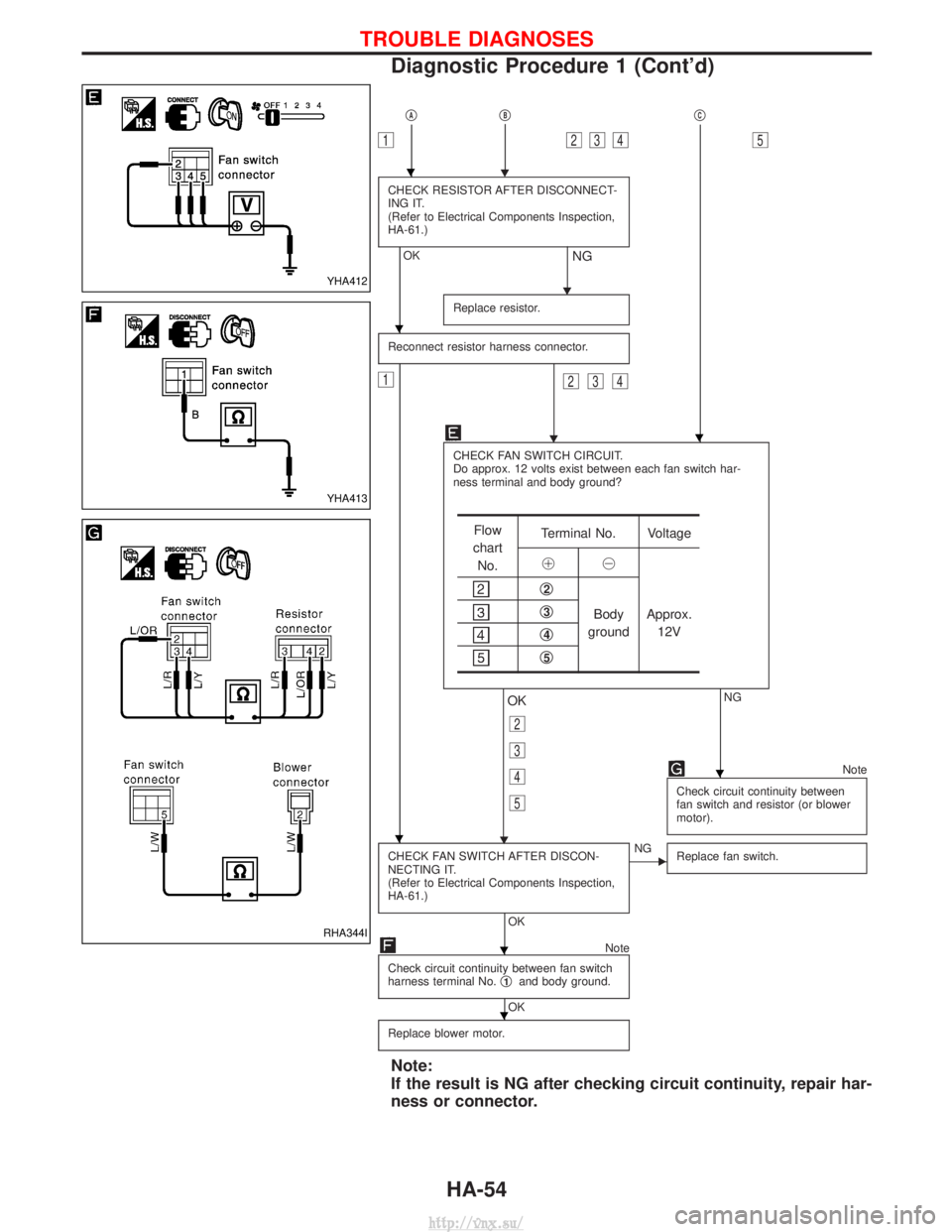
CHECK RESISTOR AFTER DISCONNECT-
ING IT.
(Refer to Electrical Components Inspection,
HA-61.)
OK
H
NG
Replace resistor.
Reconnect resistor harness connector.
1
H
234
CHECK FAN SWITCH CIRCUIT.
Do approx. 12 volts exist between each fan switch har-
ness terminal and body ground?
NG
H
OK
2
3
4
5
Note
Check circuit continuity between
fan switch and resistor (or blower
motor).
CHECK FAN SWITCH AFTER DISCON-
NECTING IT.
(Refer to Electrical Components Inspection,
HA-61.)
OK
ENG Replace fan switch.
Note
Check circuit continuity between fan switch
harness terminal No. q
1and body ground.
OK
Replace blower motor.
Note:
If the result is NG after checking circuit continuity, repair har-
ness or connector.
Flow
chart No. Terminal No. Voltage
!@
q2
Body
ground Approx.
12Vq3
q4
q5
YHA412
YHA413
RHA344I
H
H
H
H
H
H
H
TROUBLE DIAGNOSES
Diagnostic Procedure 1 (Cont'd)
HA-54
http://vnx.su/
Page 1452 of 1833
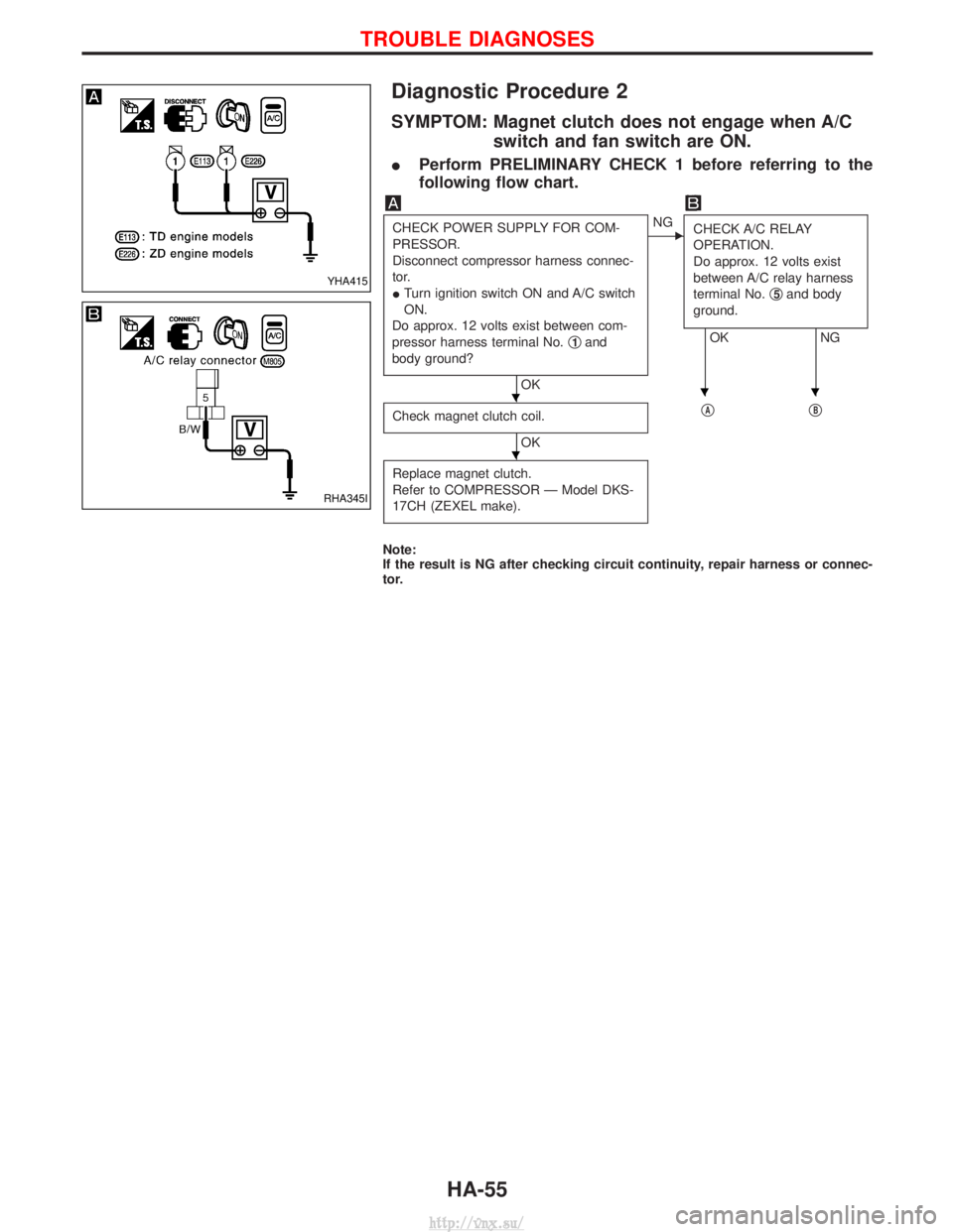
Diagnostic Procedure 2
SYMPTOM: Magnet clutch does not engage when A/Cswitch and fan switch are ON.
IPerform PRELIMINARY CHECK 1 before referring to the
following flow chart.
CHECK POWER SUPPLY FOR COM-
PRESSOR.
Disconnect compressor harness connec-
tor.
ITurn ignition switch ON and A/C switch
ON.
Do approx. 12 volts exist between com-
pressor harness terminal No. q
1and
body ground?
OK
ENG CHECK A/C RELAY
OPERATION.
Do approx. 12 volts exist
between A/C relay harness
terminal No. q
5and body
ground.
OK NG
Check magnet clutch coil.
OK q
AqB
Replace magnet clutch.
Refer to COMPRESSOR Ð Model DKS-
17CH (ZEXEL make).
Note:
If the result is NG after checking circuit continuity, repair harness or connec-
tor.
YHA415
RHA345I
HHH
H
TROUBLE DIAGNOSES
HA-55
http://vnx.su/
Page 1453 of 1833
qAqB
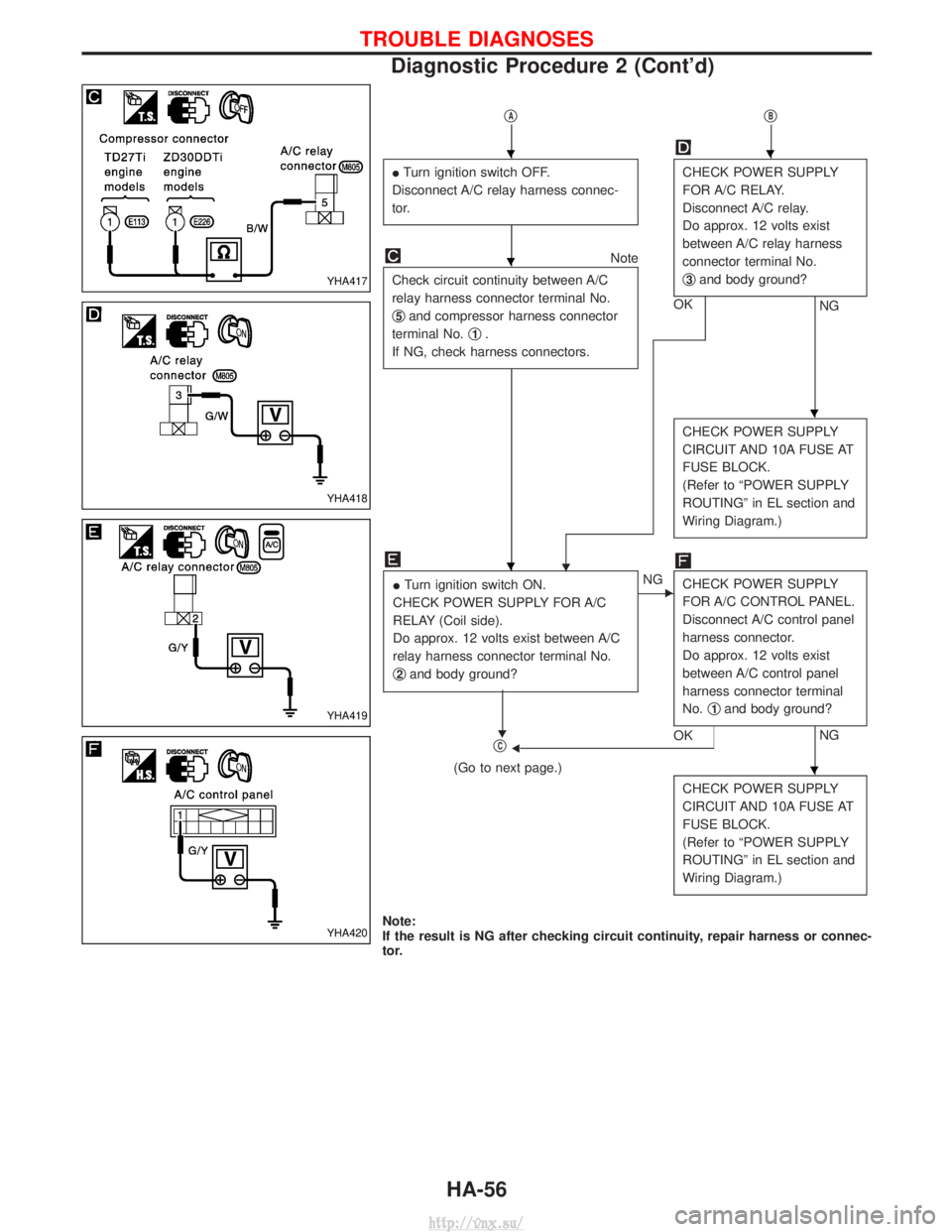
ITurn ignition switch OFF.
Disconnect A/C relay harness connec-
tor.CHECK POWER SUPPLY
FOR A/C RELAY.
Disconnect A/C relay.
Do approx. 12 volts exist
between A/C relay harness
connector terminal No.
q
3and body ground?
NG
OK
Note
Check circuit continuity between A/C
relay harness connector terminal No.
q
5and compressor harness connector
terminal No. q
1.
If NG, check harness connectors.
H
CHECK POWER SUPPLY
CIRCUIT AND 10A FUSE AT
FUSE BLOCK.
(Refer to ªPOWER SUPPLY
ROUTINGº in EL section and
Wiring Diagram.)
I Turn ignition switch ON.
CHECK POWER SUPPLY FOR A/C
RELAY (Coil side).
Do approx. 12 volts exist between A/C
relay harness connector terminal No.
q
2and body ground?
H
ENG CHECK POWER SUPPLY
FOR A/C CONTROL PANEL.
Disconnect A/C control panel
harness connector.
Do approx. 12 volts exist
between A/C control panel
harness connector terminal
No.q
1and body ground?
NG
OKFqC
(Go to next page.)
CHECK POWER SUPPLY
CIRCUIT AND 10A FUSE AT
FUSE BLOCK.
(Refer to ªPOWER SUPPLY
ROUTINGº in EL section and
Wiring Diagram.)
Note:
If the result is NG after checking circuit continuity, repair harness or connec-
tor.
YHA417
YHA418
YHA419
YHA420
HH
H
H
H
H
TROUBLE DIAGNOSES
Diagnostic Procedure 2 (Cont'd)
HA-56
http://vnx.su/
Page 1454 of 1833
qC
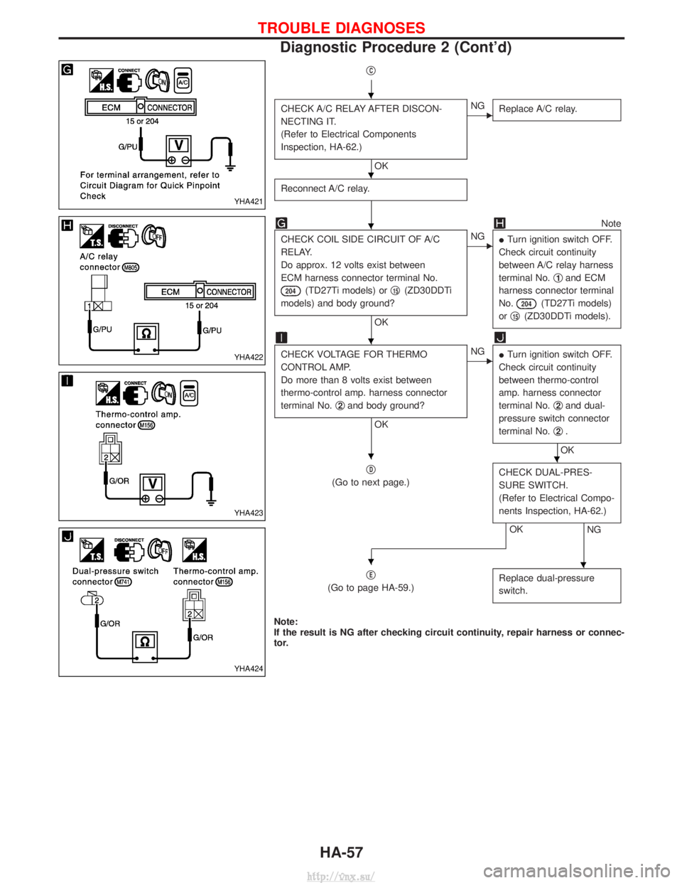
CHECK A/C RELAY AFTER DISCON-
NECTING IT.
(Refer to Electrical Components
Inspection, HA-62.)
OK
ENGReplace A/C relay.
Reconnect A/C relay.
Note
CHECK COIL SIDE CIRCUIT OF A/C
RELAY.
Do approx. 12 volts exist between
ECM harness connector terminal No.
204(TD27Ti models) or q15(ZD30DDTi
models) and body ground?
OK
ENG ITurn ignition switch OFF.
Check circuit continuity
between A/C relay harness
terminal No. q
1and ECM
harness connector terminal
No.
204(TD27Ti models)
or q
15(ZD30DDTi models).
CHECK VOLTAGE FOR THERMO
CONTROL AMP.
Do more than 8 volts exist between
thermo-control amp. harness connector
terminal No. q
2and body ground?
OK
ENG
ITurn ignition switch OFF.
Check circuit continuity
between thermo-control
amp. harness connector
terminal No. q
2and dual-
pressure switch connector
terminal No. q
2.
OK
q
D
(Go to next page.) CHECK DUAL-PRES-
SURE SWITCH.
(Refer to Electrical Compo-
nents Inspection, HA-62.)
NGOK
q
E
(Go to page HA-59.) Replace dual-pressure
switch.
Note:
If the result is NG after checking circuit continuity, repair harness or connec-
tor.
YHA421
YHA422
YHA423
YHA424
H
H
H
H
HH
HH
TROUBLE DIAGNOSES
Diagnostic Procedure 2 (Cont'd)
HA-57
http://vnx.su/
Page 1455 of 1833
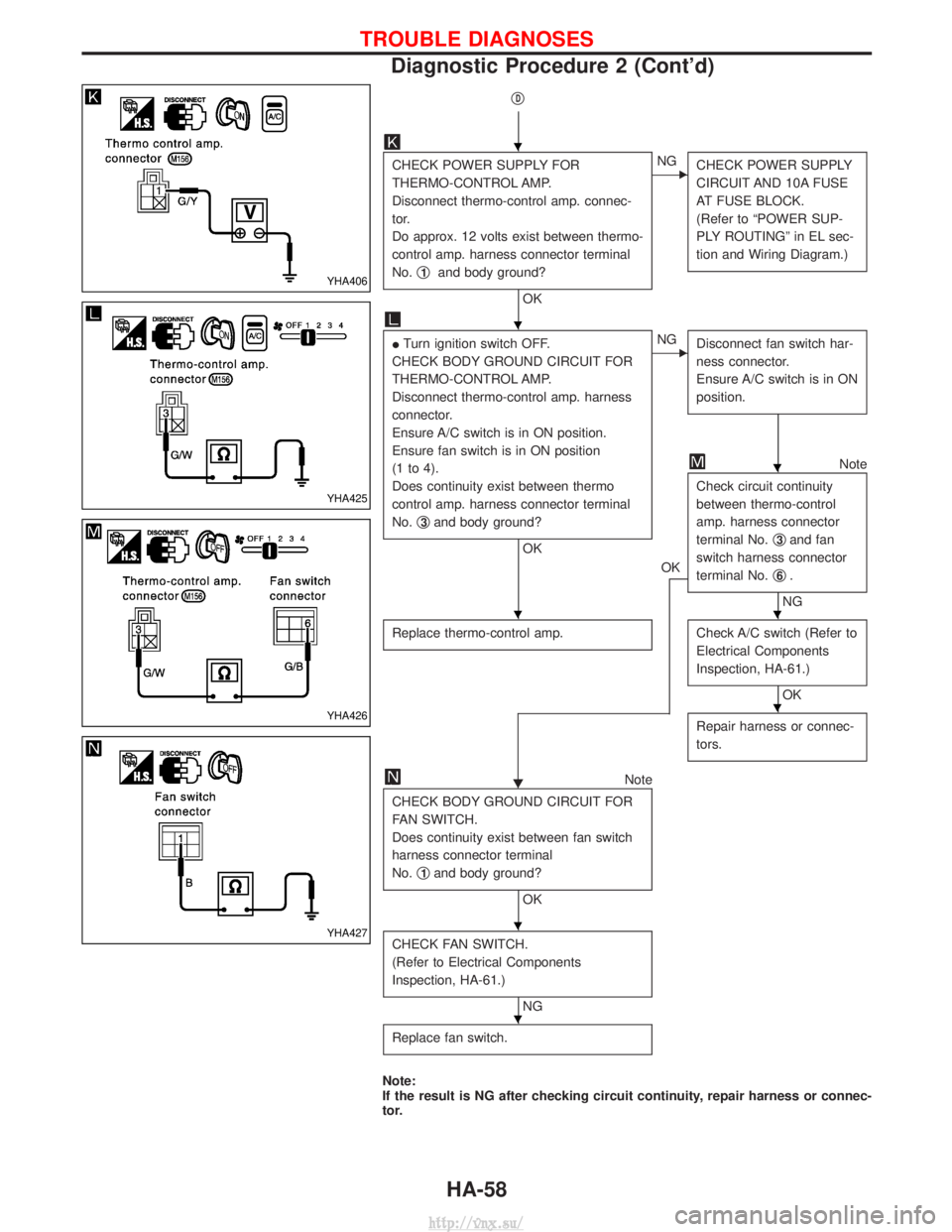
qD
CHECK POWER SUPPLY FOR
THERMO-CONTROL AMP.
Disconnect thermo-control amp. connec-
tor.
Do approx. 12 volts exist between thermo-
control amp. harness connector terminal
No.q
1and body ground?
OK
ENG
CHECK POWER SUPPLY
CIRCUIT AND 10A FUSE
AT FUSE BLOCK.
(Refer to ªPOWER SUP-
PLY ROUTINGº in EL sec-
tion and Wiring Diagram.)
ITurn ignition switch OFF.
CHECK BODY GROUND CIRCUIT FOR
THERMO-CONTROL AMP.
Disconnect thermo-control amp. harness
connector.
Ensure A/C switch is in ON position.
Ensure fan switch is in ON position
(1 to 4).
Does continuity exist between thermo
control amp. harness connector terminal
No. q
3and body ground?
OK
ENG
Disconnect fan switch har-
ness connector.
Ensure A/C switch is in ON
position.
OK
Note
Check circuit continuity
between thermo-control
amp. harness connector
terminal No. q
3and fan
switch harness connector
terminal No. q
6.
NG
Replace thermo-control amp.
Check A/C switch (Refer to
Electrical Components
Inspection, HA-61.)
OK
H Repair harness or connec-
tors.Note
CHECK BODY GROUND CIRCUIT FOR
FAN SWITCH.
Does continuity exist between fan switch
harness connector terminal
No. q
1and body ground?
OK
CHECK FAN SWITCH.
(Refer to Electrical Components
Inspection, HA-61.)
NG
Replace fan switch.
Note:
If the result is NG after checking circuit continuity, repair harness or connec-
tor.
YHA406
YHA425
YHA426
YHA427
H
H
H
HH
H
H
H
TROUBLE DIAGNOSES
Diagnostic Procedure 2 (Cont'd)
HA-58
http://vnx.su/
Page 1456 of 1833
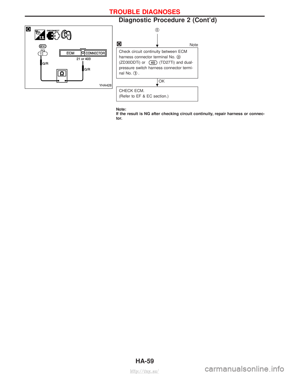
qE
Note
Check circuit continuity between ECM
harness connector terminal No. q
21
(ZD30DDTi) or403(TD27Ti) and dual-
pressure switch harness connector termi-
nal No. q
1.
OK
CHECK ECM.
(Refer to EF & EC section.)
Note:
If the result is NG after checking circuit continuity, repair harness or connec-
tor.
YHA428
H
H
TROUBLE DIAGNOSES
Diagnostic Procedure 2 (Cont'd)
HA-59
http://vnx.su/
Page 1457 of 1833
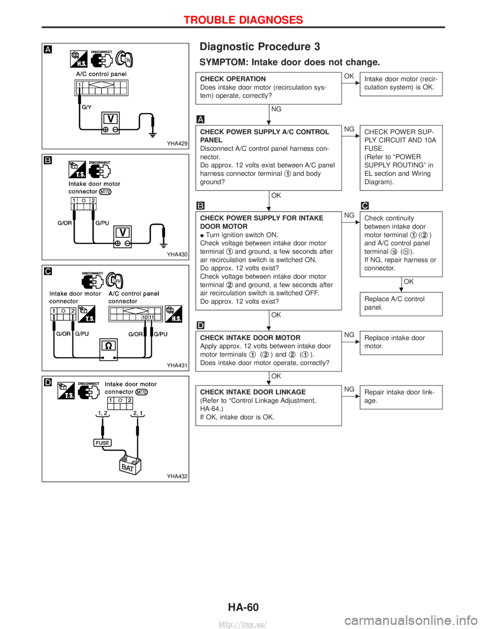
Diagnostic Procedure 3
SYMPTOM: Intake door does not change.
CHECK OPERATION
Does intake door motor (recirculation sys-
tem) operate, correctly?
NG
EOKIntake door motor (recir-
culation system) is OK.
CHECK POWER SUPPLY A/C CONTROL
PANEL
Disconnect A/C control panel harness con-
nector.
Do approx. 12 volts exist between A/C panel
harness connector terminal q
1and body
ground?
OK
ENG CHECK POWER SUP-
PLY CIRCUIT AND 10A
FUSE.
(Refer to ªPOWER
SUPPLY ROUTINGº in
EL section and Wiring
Diagram).
CHECK POWER SUPPLY FOR INTAKE
DOOR MOTOR
ITurn ignition switch ON.
Check voltage between intake door motor
terminal q
1and ground, a few seconds after
air recirculation switch is switched ON.
Do approx. 12 volts exist?
Check voltage between intake door motor
terminal q
2and ground, a few seconds after
air recirculation switch is switched OFF.
Do approx. 12 volts exist?
OK
ENG Check continuity
between intake door
motor terminal q
1(q2)
and A/C control panel
terminal q
10(q11).
If NG, repair harness or
connector.
OK
Replace A/C control
panel.
CHECK INTAKE DOOR MOTOR
Apply approx. 12 volts between intake door
motor terminals q
1(q2) and q2(q1).
Does intake door motor operate, correctly?
OK
ENG Replace intake door
motor.
CHECK INTAKE DOOR LINKAGE
(Refer to ªControl Linkage Adjustment,
HA-64.)
If OK, intake door is OK.ENGRepair intake door link-
age.
YHA429
YHA430
YHA431
YHA432
H
H
H
H
H
TROUBLE DIAGNOSES
HA-60
http://vnx.su/
Page 1458 of 1833
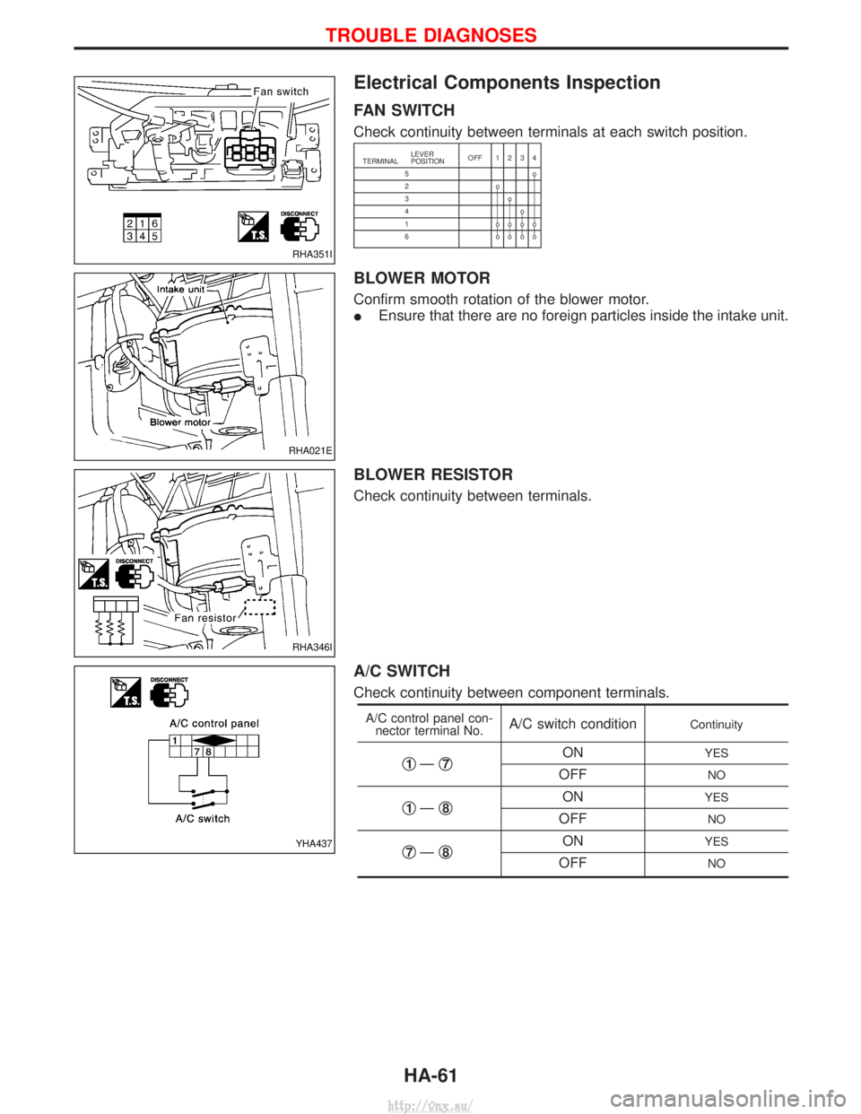
Electrical Components Inspection
FAN SWITCH
Check continuity between terminals at each switch position.
TERMINALLEVER
POSITION
OFF 1234
5o
2o
3o
4o
1 oooo
6 oooo
BLOWER MOTOR
Confirm smooth rotation of the blower motor.
I Ensure that there are no foreign particles inside the intake unit.
BLOWER RESISTOR
Check continuity between terminals.
A/C SWITCH
Check continuity between component terminals.
A/C control panel con-
nector terminal No.A/C switch conditionContinuity
q1Ð q7ONYES
OFFNO
q1Ðq8ONYES
OFFNO
q7Ðq8ONYES
OFFNO
RHA351I
RHA021E
RHA346I
YHA437
TROUBLE DIAGNOSES
HA-61
http://vnx.su/
Page 1459 of 1833
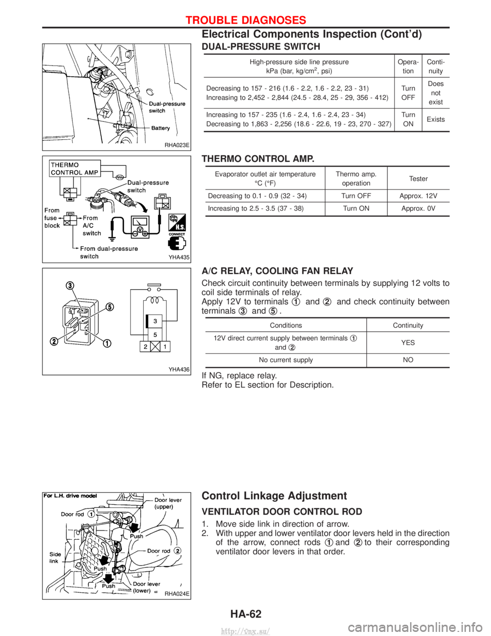
DUAL-PRESSURE SWITCH
High-pressure side line pressurekPa (bar, kg/cm2, psi) Opera-
tion Conti-
nuity
Decreasing to 157 - 216 (1.6 - 2.2, 1.6 - 2.2, 23 - 31)
Increasing to 2,452 - 2,844 (24.5 - 28.4, 25 - 29, 356 - 412) Turn
OFF Does
not
exist
Increasing to 157 - 235 (1.6 - 2.4, 1.6 - 2.4, 23 - 34)
Decreasing to 1,863 - 2,256 (18.6 - 22.6, 19 - 23, 270 - 327) Turn
ON Exists
THERMO CONTROL AMP.
Evaporator outlet air temperature
ÉC (ÉF) Thermo amp.
operation Tester
Decreasing to 0.1 - 0.9 (32 - 34) Turn OFF Approx. 12V
Increasing to 2.5 - 3.5 (37 - 38) Turn ON Approx. 0V
A/C RELAY, COOLING FAN RELAY
Check circuit continuity between terminals by supplying 12 volts to
coil side terminals of relay.
Apply 12V to terminals q
1andq2and check continuity between
terminals q
3andq5.
Conditions
Continuity
12V direct current supply between terminals q
1
andq2YES
No current supply NO
If NG, replace relay.
Refer to EL section for Description.
Control Linkage Adjustment
VENTILATOR DOOR CONTROL ROD
1. Move side link in direction of arrow.
2. With upper and lower ventilator door levers held in the direction of the arrow, connect rods q
1andq2to their corresponding
ventilator door levers in that order.
RHA023E
YHA435
YHA436
RHA024E
TROUBLE DIAGNOSES
Electrical Components Inspection (Cont'd)
HA-62
http://vnx.su/
Page 1460 of 1833
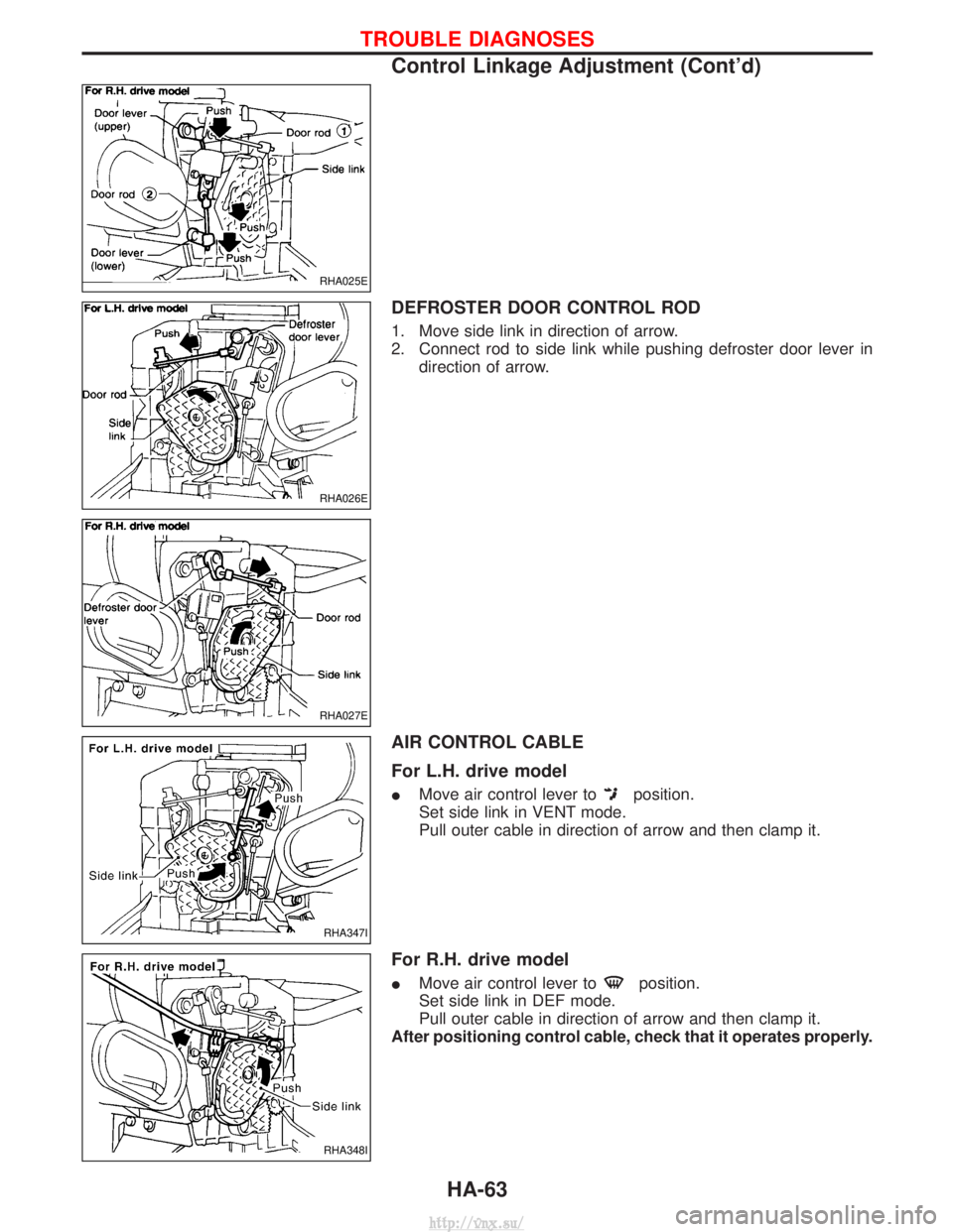
DEFROSTER DOOR CONTROL ROD
1. Move side link in direction of arrow.
2. Connect rod to side link while pushing defroster door lever indirection of arrow.
AIR CONTROL CABLE
For L.H. drive model
IMove air control lever toposition.
Set side link in VENT mode.
Pull outer cable in direction of arrow and then clamp it.
For R.H. drive model
I Move air control lever toposition.
Set side link in DEF mode.
Pull outer cable in direction of arrow and then clamp it.
After positioning control cable, check that it operates properly.
RHA025E
RHA026E
RHA027E
RHA347I
RHA348I
TROUBLE DIAGNOSES
Control Linkage Adjustment (Cont'd)
HA-63
http://vnx.su/