NISSAN TERRANO 2004 Service Repair Manual
TERRANO 2004
NISSAN
NISSAN
https://www.carmanualsonline.info/img/5/57394/w960_57394-0.png
NISSAN TERRANO 2004 Service Repair Manual
Trending: torque, sport mode, alarm, steering wheel adjustment, seats, wiring diagram, battery capacity
Page 1641 of 1833
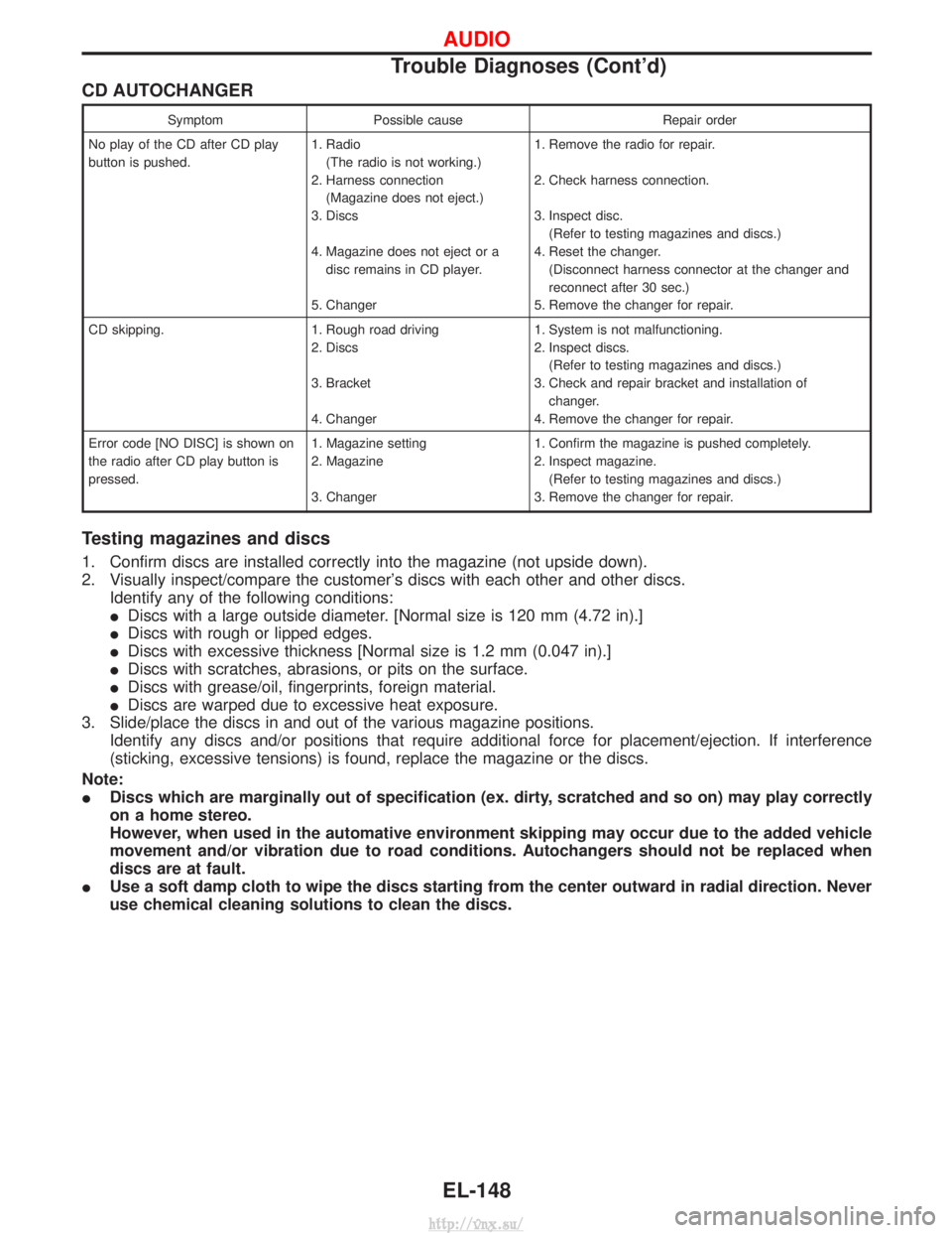
CD AUTOCHANGER
SymptomPossible cause Repair order
No play of the CD after CD play
button is pushed. 1. Radio
(The radio is not working.)
2. Harness connection (Magazine does not eject.)
3. Discs
4. Magazine does not eject or a disc remains in CD player.
5. Changer 1. Remove the radio for repair.
2. Check harness connection.
3. Inspect disc.
(Refer to testing magazines and discs.)
4. Reset the changer. (Disconnect harness connector at the changer and
reconnect after 30 sec.)
5. Remove the changer for repair.
CD skipping. 1. Rough road driving 2. Discs
3. Bracket
4. Changer1. System is not malfunctioning.
2. Inspect discs.
(Refer to testing magazines and discs.)
3. Check and repair bracket and installation of changer.
4. Remove the changer for repair.
Error code [NO DISC] is shown on
the radio after CD play button is
pressed. 1. Magazine setting
2. Magazine
3. Changer1. Confirm the magazine is pushed completely.
2. Inspect magazine.
(Refer to testing magazines and discs.)
3. Remove the changer for repair.
Testing magazines and discs
1. Confirm discs are installed correctly into the magazine (not upside down).
2. Visually inspect/compare the customer's discs with each other and other discs. Identify any of the following conditions:
IDiscs with a large outside diameter. [Normal size is 120 mm (4.72 in).]
I Discs with rough or lipped edges.
I Discs with excessive thickness [Normal size is 1.2 mm (0.047 in).]
I Discs with scratches, abrasions, or pits on the surface.
I Discs with grease/oil, fingerprints, foreign material.
I Discs are warped due to excessive heat exposure.
3. Slide/place the discs in and out of the various magazine positions. Identify any discs and/or positions that require additional force for placement/ejection. If interference
(sticking, excessive tensions) is found, replace the magazine or the discs.
Note:
I Discs which are marginally out of specification (ex. dirty, scratched and so on) may play correctly
on a home stereo.
However, when used in the automative environment skipping may occur due to the added vehicle
movement and/or vibration due to road conditions. Autochangers should not be replaced when
discs are at fault.
I Use a soft damp cloth to wipe the discs starting from the center outward in radial direction. Never
use chemical cleaning solutions to clean the discs.
AUDIO
Trouble Diagnoses (Cont'd)
EL-148
http://vnx.su/
Page 1642 of 1833
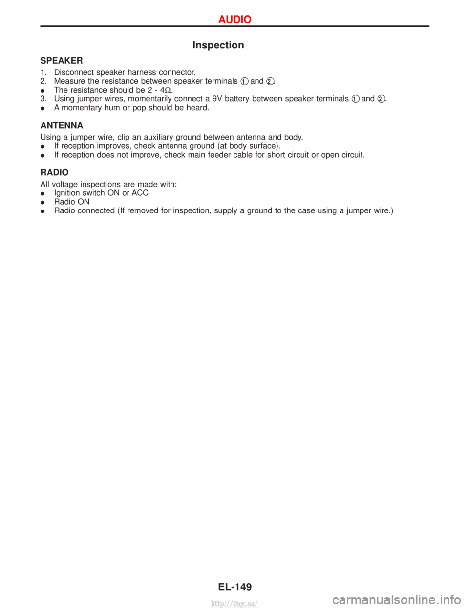
Inspection
SPEAKER
1. Disconnect speaker harness connector.
2. Measure the resistance between speaker terminalsq
1andq2.
I The resistance should be2-4 W.
3. Using jumper wires, momentarily connect a 9V battery between speaker terminals q
1andq2.
I A momentary hum or pop should be heard.
ANTENNA
Using a jumper wire, clip an auxiliary ground between antenna and body.
IIf reception improves, check antenna ground (at body surface).
I If reception does not improve, check main feeder cable for short circuit or open circuit.
RADIO
All voltage inspections are made with:
IIgnition switch ON or ACC
I Radio ON
I Radio connected (If removed for inspection, supply a ground to the case using a jumper wire.)
AUDIO
EL-149
http://vnx.su/
Page 1643 of 1833
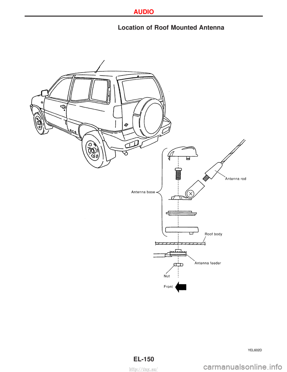
Location of Roof Mounted Antenna
YEL602D
AUDIO
EL-150
http://vnx.su/
Page 1644 of 1833
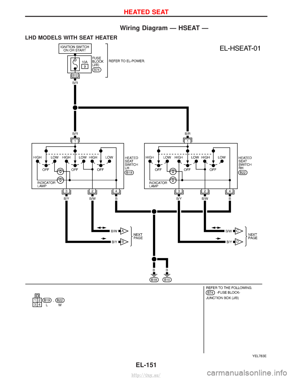
Wiring Diagram Ð HSEAT Ð
LHD MODELS WITH SEAT HEATER
YEL783E
HEATED SEAT
EL-151
http://vnx.su/
Page 1645 of 1833
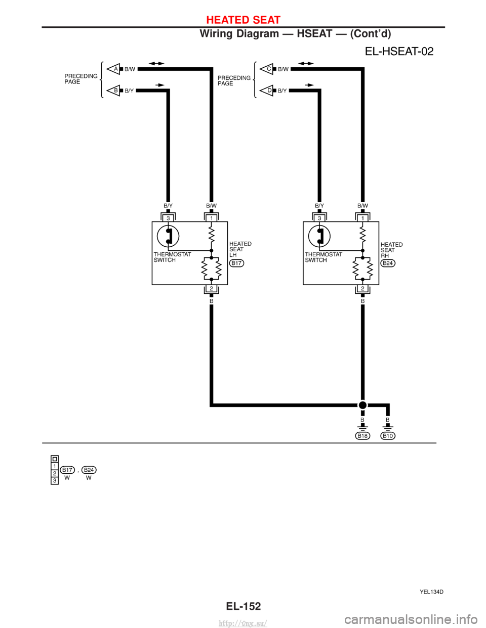
YEL134D
HEATED SEAT
Wiring Diagram Ð HSEAT Ð (Cont'd)EL-152
http://vnx.su/
Page 1646 of 1833
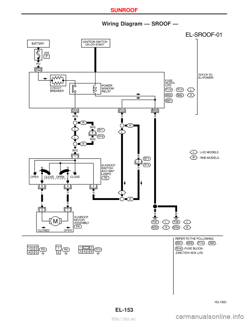
Wiring Diagram Ð SROOF Ð
YEL135D
SUNROOF
EL-153
http://vnx.su/
Page 1647 of 1833
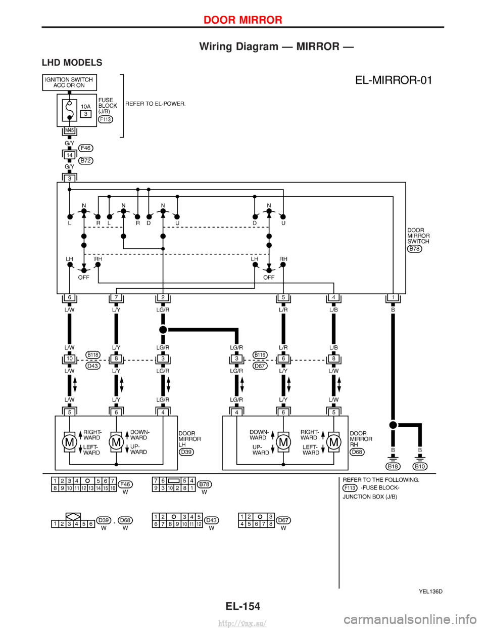
Wiring Diagram Ð MIRROR Ð
LHD MODELS
YEL136D
DOOR MIRROR
EL-154
http://vnx.su/
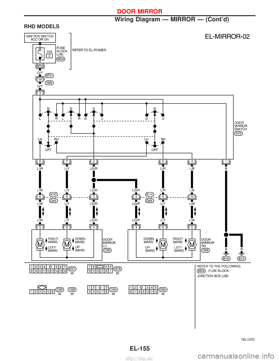
Page 1648 of 1833
RHD MODELS
YEL137D
DOOR MIRROR
Wiring Diagram Ð MIRROR Ð (Cont'd)EL-155
http://vnx.su/
Page 1649 of 1833
![NISSAN TERRANO 2004 Service Repair Manual System Description
Power is supplied at all times
Ifrom 40A fusible link (letter F, located in fuse and fusible link box)
I through circuit breaker [built-in fuse block (J/B)]
I to power window relay NISSAN TERRANO 2004 Service Repair Manual System Description
Power is supplied at all times
Ifrom 40A fusible link (letter F, located in fuse and fusible link box)
I through circuit breaker [built-in fuse block (J/B)]
I to power window relay](/img/5/57394/w960_57394-1648.png)
System Description
Power is supplied at all times
Ifrom 40A fusible link (letter F, located in fuse and fusible link box)
I through circuit breaker [built-in fuse block (J/B)]
I to power window relay [built-in fuse block (J/B)].
With ignition switch in ON or START position, power is supplied
I to power window relay
Ground is supplied to power window relay
I through body grounds F36, F47 (LHD models) or M33, M754 (RHD models).
The power window relay is energized and power is supplied
I through power window relay
I to power window main switch terminal 1,
I to power window sub-switch front passenger side terminal 5,
I to power window sub-switch rear LH and RH terminal 5 (models with rear power window).
MANUAL OPERATION
Front Door (Driver Side)
Ground is supplied
Ito power window main switch terminal 3
I through body grounds B10 and B18.
WINDOW UP
When the driver's window switch in the power window main switch is pressed in the up position, power is
supplied
I through power window main switch terminal 9
I to driver side power window motor terminal 2.
Ground is supplied
I through power window main switch terminal 1
I to driver side power window motor terminal 8.
Then, the motor raises the window until the switch is released.
WINDOW DOWN
When the driver's window switch in the power window main switch is pressed in the down position, power is
supplied
I through power window main switch terminal 8
I to driver side power window motor terminal 1.
Ground is supplied
I to driver side power window motor terminal 2
I through power window main switch terminal 9.
Then, the motor lowers the window until the switch is released.
Front Door (Passenger Side)
Ground is supplied
I to power window main switch terminal 3
I through body grounds B10 and B18.
NOTE:
Numbers in parentheses are terminal numbers, when power window switch is pressed in the UP and DOWN
positions respectively.
POWER WINDOW MAIN SWITCH OPERATION
Power is supplied
I through power window main switch (5, 6)
I to power window sub-switch front passenger side (3, 4).
The subsequent operation is the same as the front power window sub-switch operation.
FRONT POWER WINDOW SUB-SWITCH OPERATION
Power is supplied
I through front power window sub-switch (1, 2)
I to power window motor front passenger side (2, 1).
Ground is supplied
I to front passenger side power window motor (1, 2)
I through front power window sub-switch (2, 1)
I to front power window sub-switch (4, 3)
POWER WINDOW
EL-156
http://vnx.su/
Page 1650 of 1833
Ithrough power window main switch (6, 5).
Then, the motor raises or lowers the window until the switch is released.
Rear Door
Rear door windows will raise and lower in the same manner as passenger's door window.
POWER WINDOW LOCK
The power window lock is designed to lock operation of all windows except for driver's door window.
When the lock switch is pressed to lock position, ground of the sub-switches in the power window main switch
is disconnected. This prevents the power window motors from operating.
AUTO OPERATION
The power window AUTO feature enables the driver to open the driver's window without holding the window
switch in the down position.
The AUTO feature operates on the driver's window.
POWER WINDOW
System Description (Cont'd)
EL-157
http://vnx.su/
Trending: brake rotor, warning light, brake pads, power steering, diagram, jacking points, battery location

![NISSAN TERRANO 2004 Service Repair Manual System Description
Power is supplied at all times
Ifrom 40A fusible link (letter F, located in fuse and fusible link box)
I through circuit breaker [built-in fuse block (J/B)]
I to power window relay NISSAN TERRANO 2004 Service Repair Manual System Description
Power is supplied at all times
Ifrom 40A fusible link (letter F, located in fuse and fusible link box)
I through circuit breaker [built-in fuse block (J/B)]
I to power window relay](/img/5/57394/w960_57394-1648.png)
