NISSAN TERRANO 2004 Service Repair Manual
Manufacturer: NISSAN, Model Year: 2004, Model line: TERRANO, Model: NISSAN TERRANO 2004Pages: 1833, PDF Size: 53.42 MB
Page 221 of 1833
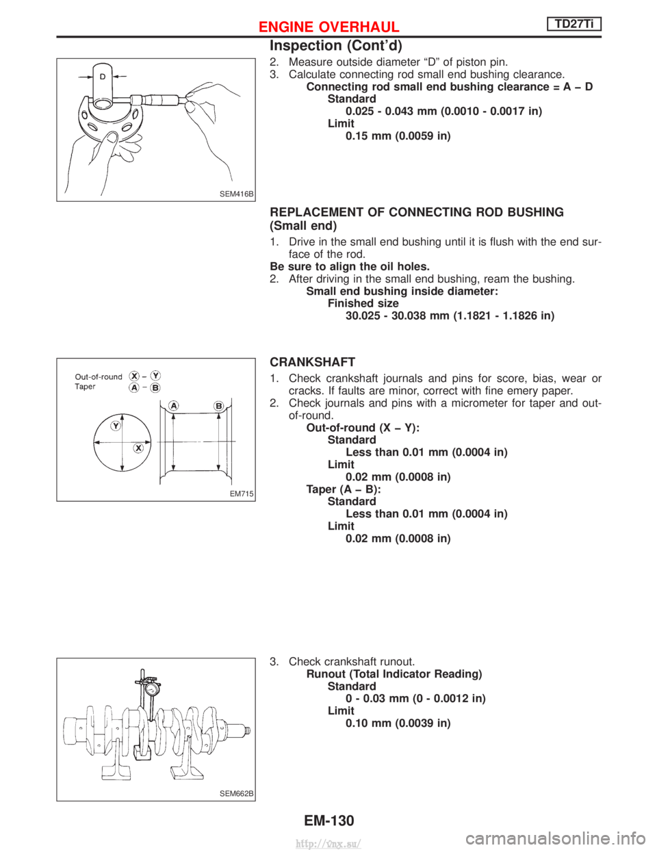
2. Measure outside diameter ªDº of piston pin.
3. Calculate connecting rod small end bushing clearance.Connecting rod small end bushing clearance = A þ DStandard0.025 - 0.043 mm (0.0010 - 0.0017 in)
Limit 0.15 mm (0.0059 in)
REPLACEMENT OF CONNECTING ROD BUSHING
(Small end)
1. Drive in the small end bushing until it is flush with the end sur- face of the rod.
Be sure to align the oil holes.
2. After driving in the small end bushing, ream the bushing. Small end bushing inside diameter:Finished size30.025 - 30.038 mm (1.1821 - 1.1826 in)
CRANKSHAFT
1. Check crankshaft journals and pins for score, bias, wear or cracks. If faults are minor, correct with fine emery paper.
2. Check journals and pins with a micrometer for taper and out- of-round.Out-of-round (X þ Y): StandardLess than 0.01 mm (0.0004 in)
Limit 0.02 mm (0.0008 in)
Taper (A þ B): StandardLess than 0.01 mm (0.0004 in)
Limit 0.02 mm (0.0008 in)
3. Check crankshaft runout. Runout (Total Indicator Reading)Standard0 - 0.03 mm (0 - 0.0012 in)
Limit 0.10 mm (0.0039 in)
SEM416B
EM715
SEM662B
ENGINE OVERHAULTD27Ti
Inspection (Cont'd)
EM-130
http://vnx.su/
Page 222 of 1833
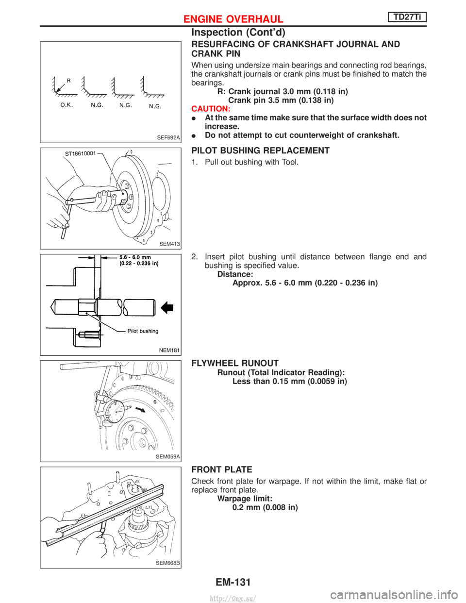
RESURFACING OF CRANKSHAFT JOURNAL AND
CRANK PIN
When using undersize main bearings and connecting rod bearings,
the crankshaft journals or crank pins must be finished to match the
bearings.R: Crank journal 3.0 mm (0.118 in)Crank pin 3.5 mm (0.138 in)
CAUTION:
I At the same time make sure that the surface width does not
increase.
I Do not attempt to cut counterweight of crankshaft.
PILOT BUSHING REPLACEMENT
1. Pull out bushing with Tool.
2. Insert pilot bushing until distance between flange end and
bushing is specified value.Distance: Approx. 5.6 - 6.0 mm (0.220 - 0.236 in)
FLYWHEEL RUNOUT
Runout (Total Indicator Reading):Less than 0.15 mm (0.0059 in)
FRONT PLATE
Check front plate for warpage. If not within the limit, make flat or
replace front plate. Warpage limit:0.2 mm (0.008 in)
SEF692A
SEM413
NEM181
SEM059A
SEM668B
ENGINE OVERHAULTD27Ti
Inspection (Cont'd)
EM-131
http://vnx.su/
Page 223 of 1833
GEAR TRAIN
Camshaft drive gear, injection pump drive gear, oil pump gear,
idler gear, crankshaft gear and vacuum pump gear.
1. If gear tooth and key have scratches or are excessively worn,replace gear and key.
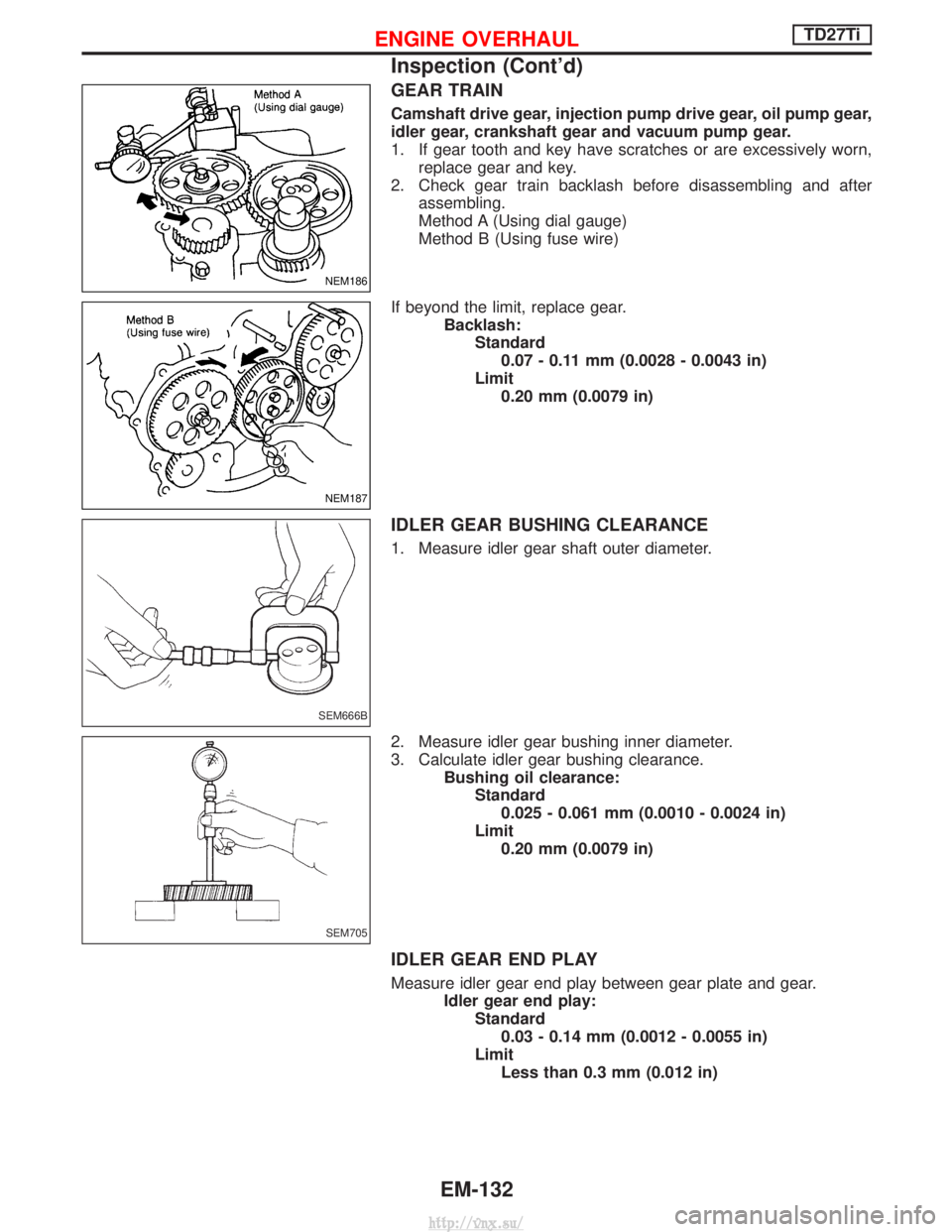
2. Check gear train backlash before disassembling and after assembling.
Method A (Using dial gauge)
Method B (Using fuse wire)
If beyond the limit, replace gear. Backlash:Standard0.07 - 0.11 mm (0.0028 - 0.0043 in)
Limit 0.20 mm (0.0079 in)
IDLER GEAR BUSHING CLEARANCE
1. Measure idler gear shaft outer diameter.
2. Measure idler gear bushing inner diameter.
3. Calculate idler gear bushing clearance. Bushing oil clearance:Standard0.025 - 0.061 mm (0.0010 - 0.0024 in)
Limit 0.20 mm (0.0079 in)
IDLER GEAR END PLAY
Measure idler gear end play between gear plate and gear. Idler gear end play:Standard0.03 - 0.14 mm (0.0012 - 0.0055 in)
Limit Less than 0.3 mm (0.012 in)
NEM186
NEM187
SEM666B
SEM705
ENGINE OVERHAULTD27Ti
Inspection (Cont'd)
EM-132
http://vnx.su/
Page 224 of 1833
REPLACEMENT OF IDLER GEAR BUSHING
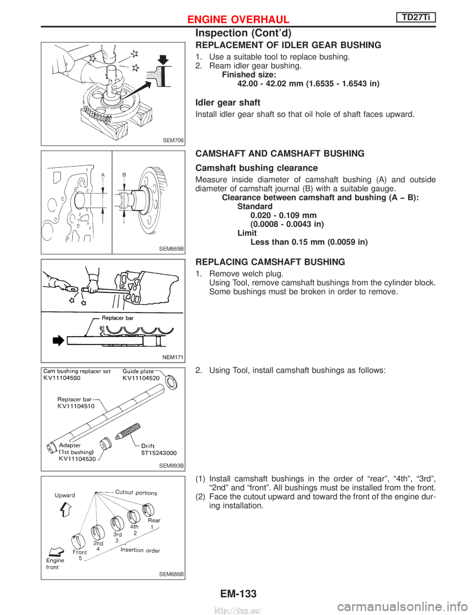
1. Use a suitable tool to replace bushing.
2. Ream idler gear bushing.Finished size:42.00 - 42.02 mm (1.6535 - 1.6543 in)
Idler gear shaft
Install idler gear shaft so that oil hole of shaft faces upward.
CAMSHAFT AND CAMSHAFT BUSHING
Camshaft bushing clearance
Measure inside diameter of camshaft bushing (A) and outside
diameter of camshaft journal (B) with a suitable gauge. Clearance between camshaft and bushing (A þ B):Standard0.020 - 0.109 mm
(0.0008 - 0.0043 in)
Limit Less than 0.15 mm (0.0059 in)
REPLACING CAMSHAFT BUSHING
1. Remove welch plug. Using Tool, remove camshaft bushings from the cylinder block.
Some bushings must be broken in order to remove.
2. Using Tool, install camshaft bushings as follows:
(1) Install camshaft bushings in the order of ªrearº, ª4thº, ª3rdº, ª2ndº and ªfrontº. All bushings must be installed from the front.
(2) Face the cutout upward and toward the front of the engine dur- ing installation.
SEM706
SEM669B
NEM171
SEM993B
SEM686B
ENGINE OVERHAULTD27Ti
Inspection (Cont'd)
EM-133
http://vnx.su/
Page 225 of 1833
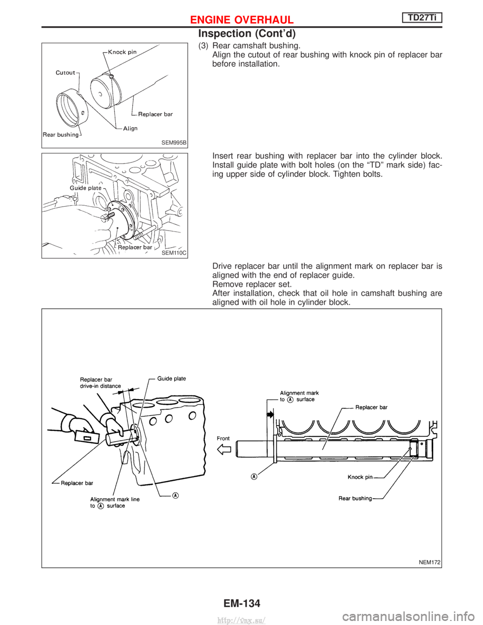
(3) Rear camshaft bushing.Align the cutout of rear bushing with knock pin of replacer bar
before installation.
Insert rear bushing with replacer bar into the cylinder block.
Install guide plate with bolt holes (on the ªTDº mark side) fac-
ing upper side of cylinder block. Tighten bolts.
Drive replacer bar until the alignment mark on replacer bar is
aligned with the end of replacer guide.
Remove replacer set.
After installation, check that oil hole in camshaft bushing are
aligned with oil hole in cylinder block.
SEM995B
SEM110C
NEM172
ENGINE OVERHAULTD27Ti
Inspection (Cont'd)
EM-134
http://vnx.su/
Page 226 of 1833
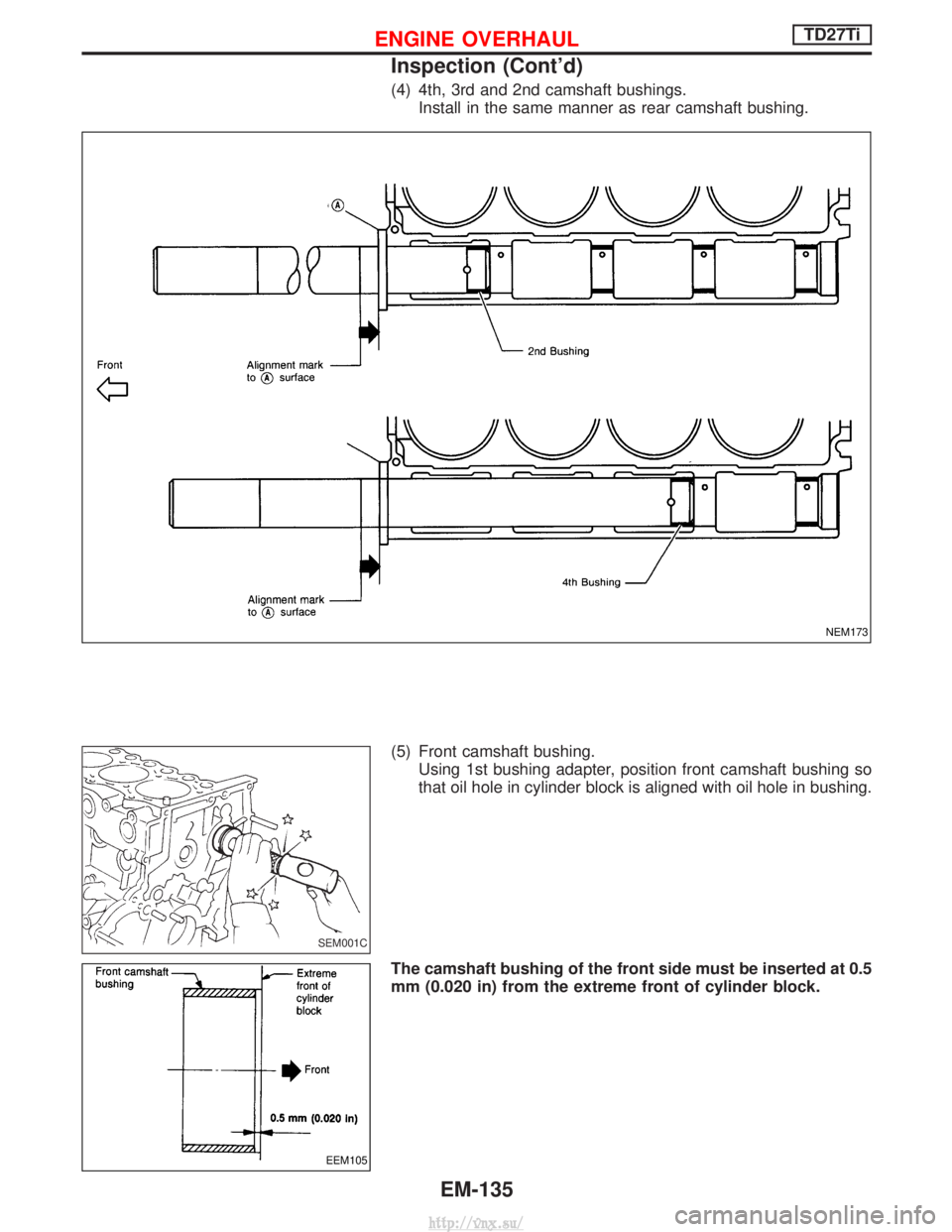
(4) 4th, 3rd and 2nd camshaft bushings.Install in the same manner as rear camshaft bushing.
(5) Front camshaft bushing. Using 1st bushing adapter, position front camshaft bushing so
that oil hole in cylinder block is aligned with oil hole in bushing.
The camshaft bushing of the front side must be inserted at 0.5
mm (0.020 in) from the extreme front of cylinder block.
NEM173
SEM001C
EEM105
ENGINE OVERHAULTD27Ti
Inspection (Cont'd)
EM-135
http://vnx.su/
Page 227 of 1833
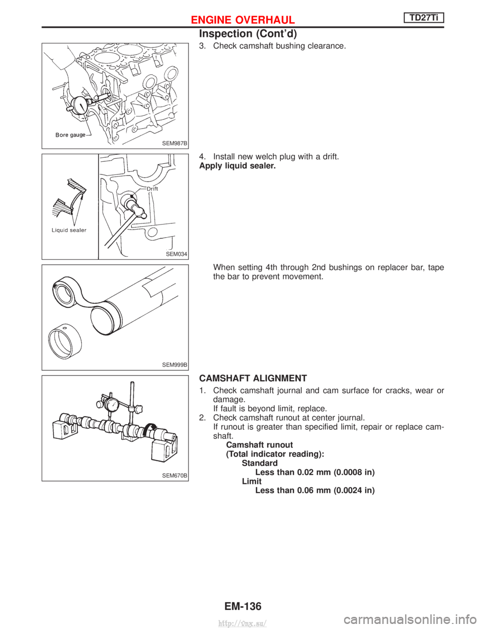
3. Check camshaft bushing clearance.
4. Install new welch plug with a drift.
Apply liquid sealer.When setting 4th through 2nd bushings on replacer bar, tape
the bar to prevent movement.
CAMSHAFT ALIGNMENT
1. Check camshaft journal and cam surface for cracks, wear ordamage.
If fault is beyond limit, replace.
2. Check camshaft runout at center journal. If runout is greater than specified limit, repair or replace cam-
shaft.Camshaft runout
(Total indicator reading): StandardLess than 0.02 mm (0.0008 in)
Limit Less than 0.06 mm (0.0024 in)
SEM987B
SEM034
SEM999B
SEM670B
ENGINE OVERHAULTD27Ti
Inspection (Cont'd)
EM-136
http://vnx.su/
Page 228 of 1833
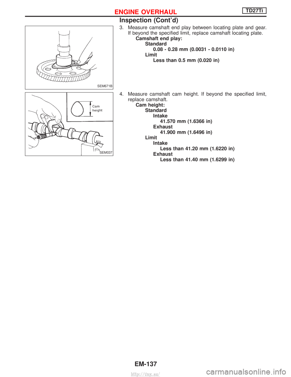
3. Measure camshaft end play between locating plate and gear.If beyond the specified limit, replace camshaft locating plate.Camshaft end play: Standard0.08 - 0.28 mm (0.0031 - 0.0110 in)
Limit Less than 0.5 mm (0.020 in)
4. Measure camshaft cam height. If beyond the specified limit, replace camshaft.Cam height: StandardIntake41.570 mm (1.6366 in)
Exhaust 41.900 mm (1.6496 in)
Limit IntakeLess than 41.20 mm (1.6220 in)
Exhaust Less than 41.40 mm (1.6299 in)
SEM671B
SEM037
ENGINE OVERHAULTD27Ti
Inspection (Cont'd)
EM-137
http://vnx.su/
Page 229 of 1833
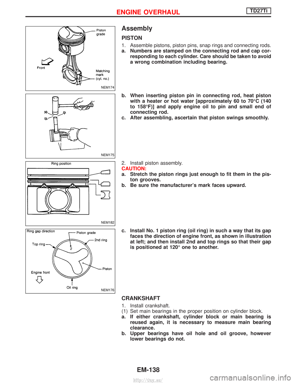
Assembly
PISTON
1. Assemble pistons, piston pins, snap rings and connecting rods.
a. Numbers are stamped on the connecting rod and cap cor-responding to each cylinder. Care should be taken to avoid
a wrong combination including bearing.
b. When inserting piston pin in connecting rod, heat piston with a heater or hot water [approximately 60 to 70ÉC (140
to 158ÉF)] and apply engine oil to pin and small end of
connecting rod.
c. After assembling, ascertain that piston swings smoothly.
2. Install piston assembly.
CAUTION:
a. Stretch the piston rings just enough to fit them in the pis- ton grooves.
b. Be sure the manufacturer's mark faces upward.
c. Install No. 1 piston ring (oil ring) in such a way that its gap faces the direction of engine front, as shown in illustration
at left; and then install 2nd and top rings so that their gap
is positioned at 120É one to another.
CRANKSHAFT
1. Install crankshaft.
(1) Set main bearings in the proper position on cylinder block.
a. If either crankshaft, cylinder block or main bearing isreused again, it is necessary to measure main bearing
clearance.
b. Upper bearings have oil hole and oil groove, however lower bearings do not.
NEM174
NEM175
NEM182
NEM176
ENGINE OVERHAULTD27Ti
EM-138
http://vnx.su/
Page 230 of 1833
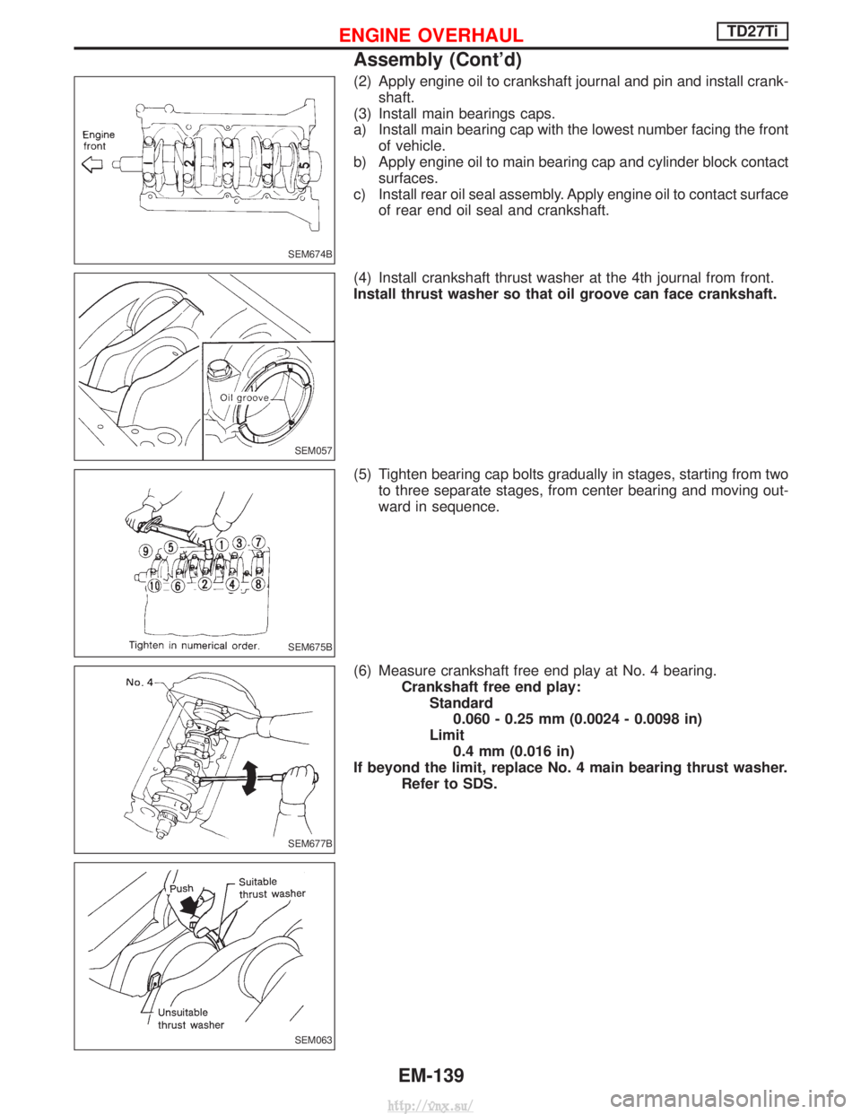
(2) Apply engine oil to crankshaft journal and pin and install crank-shaft.
(3) Install main bearings caps.
a) Install main bearing cap with the lowest number facing the front of vehicle.
b) Apply engine oil to main bearing cap and cylinder block contact surfaces.
c) Install rear oil seal assembly. Apply engine oil to contact surface of rear end oil seal and crankshaft.
(4) Install crankshaft thrust washer at the 4th journal from front.
Install thrust washer so that oil groove can face crankshaft.
(5) Tighten bearing cap bolts gradually in stages, starting from two to three separate stages, from center bearing and moving out-
ward in sequence.
(6) Measure crankshaft free end play at No. 4 bearing. Crankshaft free end play:Standard0.060 - 0.25 mm (0.0024 - 0.0098 in)
Limit 0.4 mm (0.016 in)
If beyond the limit, replace No. 4 main bearing thrust washer. Refer to SDS.
SEM674B
SEM057
SEM675B
SEM677B
SEM063
ENGINE OVERHAULTD27Ti
Assembly (Cont'd)
EM-139
http://vnx.su/