NISSAN TERRANO 2004 Service Repair Manual
Manufacturer: NISSAN, Model Year: 2004, Model line: TERRANO, Model: NISSAN TERRANO 2004Pages: 1833, PDF Size: 53.42 MB
Page 191 of 1833
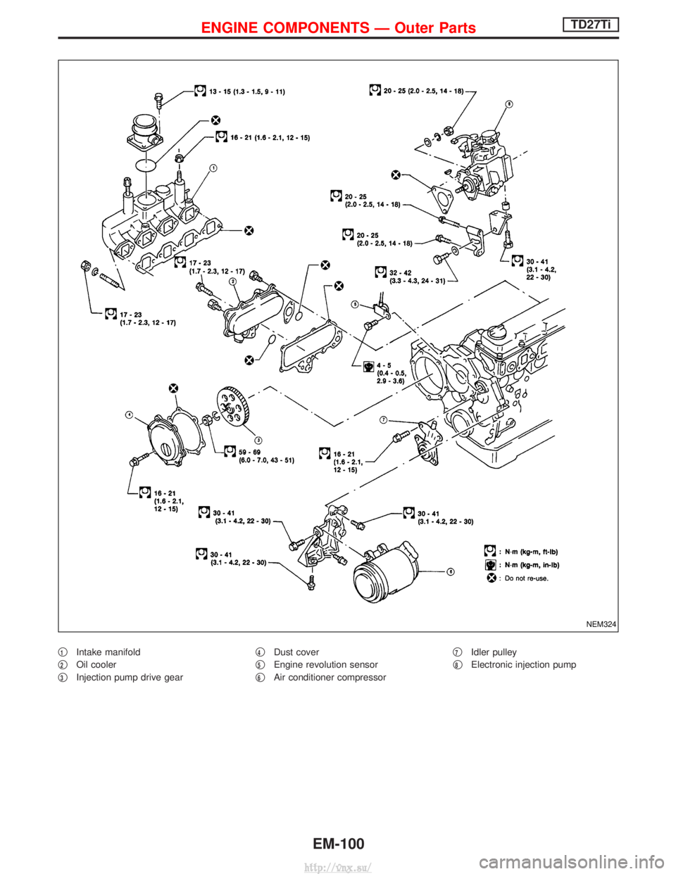
q1Intake manifold
q
2Oil cooler
q
3Injection pump drive gear q
4Dust cover
q
5Engine revolution sensor
q
6Air conditioner compressor q
7Idler pulley
q
8Electronic injection pump
NEM324
ENGINE COMPONENTS Ð Outer PartsTD27Ti
EM-100
http://vnx.su/
Page 192 of 1833
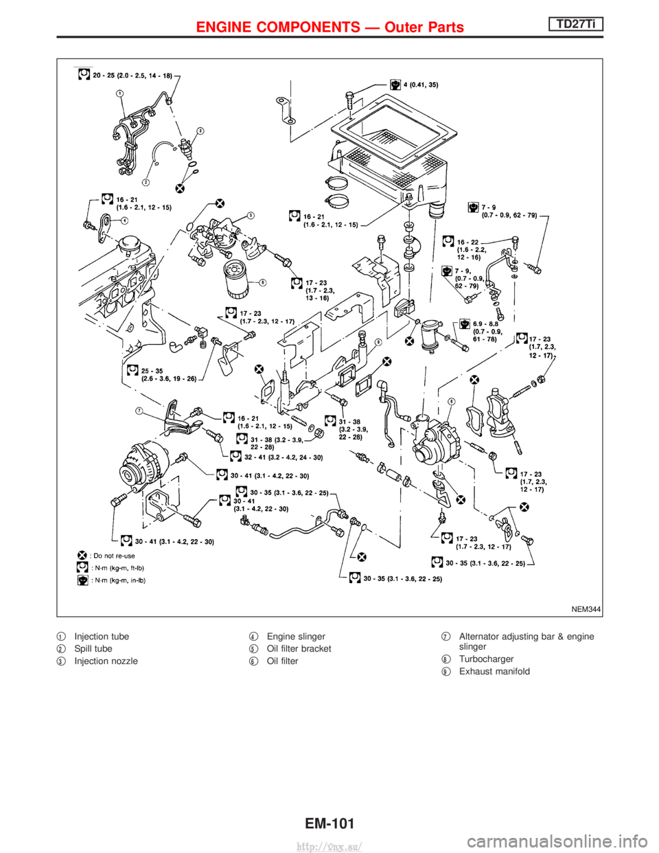
q1Injection tube
q
2Spill tube
q
3Injection nozzle q
4Engine slinger
q
5Oil filter bracket
q
6Oil filter q
7Alternator adjusting bar & engine
slinger
q
8Turbocharger
q
9Exhaust manifold
NEM344
ENGINE COMPONENTS Ð Outer PartsTD27Ti
EM-101
http://vnx.su/
Page 193 of 1833
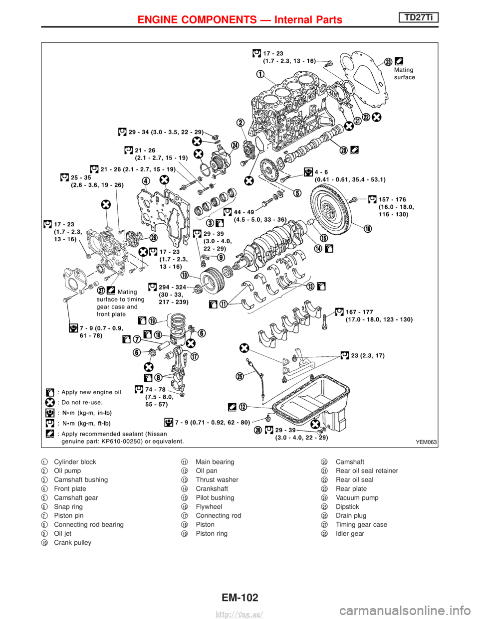
q1Cylinder block
q
2Oil pump
q
3Camshaft bushing
q
4Front plate
q
5Camshaft gear
q
6Snap ring
q
7Piston pin
q
8Connecting rod bearing
q
9Oil jet
q
10Crank pulley q
11Main bearing
q
12Oil pan
q
13Thrust washer
q
14Crankshaft
q
15Pilot bushing
q
16Flywheel
q
17Connecting rod
q
18Piston
q
19Piston ring q
20Camshaft
q
21Rear oil seal retainer
q
22Rear oil seal
q
23Rear plate
q
24Vacuum pump
q
25Dipstick
q
26Drain plug
q
27Timing gear case
q
28Idler gear
YEM063
ENGINE COMPONENTS Ð Internal PartsTD27Ti
EM-102
http://vnx.su/
Page 194 of 1833
Measurement of Compression Pressure
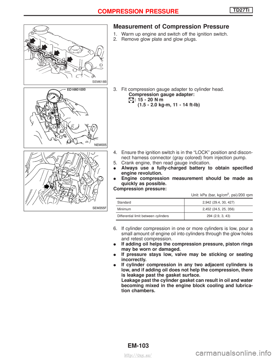
1. Warm up engine and switch off the ignition switch.
2. Remove glow plate and glow plugs.
3. Fit compression gauge adapter to cylinder head.Compression gauge adapter:
:15-20N ×m
(1.5 - 2.0 kg-m, 11 - 14 ft-lb)
4. Ensure the ignition switch is in the ªLOCKº position and discon- nect harness connector (gray colored) from injection pump.
5. Crank engine, then read gauge indication.
I Always use a fully-charged battery to obtain specified
engine revolution.
I Engine compression measurement should be made as
quickly as possible.
Compression pressure:
Unit: kPa (bar, kg/cm2, psi)/200 rpm
Standard 2,942 (29.4, 30, 427)
Minimum 2,452 (24.5, 25, 356)
Differential limit between cylinders 294 (2.9, 3, 43)
6. If cylinder compression in one or more cylinders is low, pour a small amount of engine oil into cylinders through the glow holes
and retest compression.
I If adding oil helps the compression pressure, piston rings
may be worn or damaged.
I If pressure stays low, valve may be sticking or seating
incorrectly.
I If cylinder compression in any two adjacent cylinders is
low, and if adding oil does not help the compression, there
is leakage past the gasket surface.
Leakage past the cylinder gasket can result in oil and water
becoming mixed in the engine block cooling and lubrica-
tion chambers.
SEM618B
NEM005
SEM355F
COMPRESSION PRESSURETD27Ti
EM-103
http://vnx.su/
Page 195 of 1833
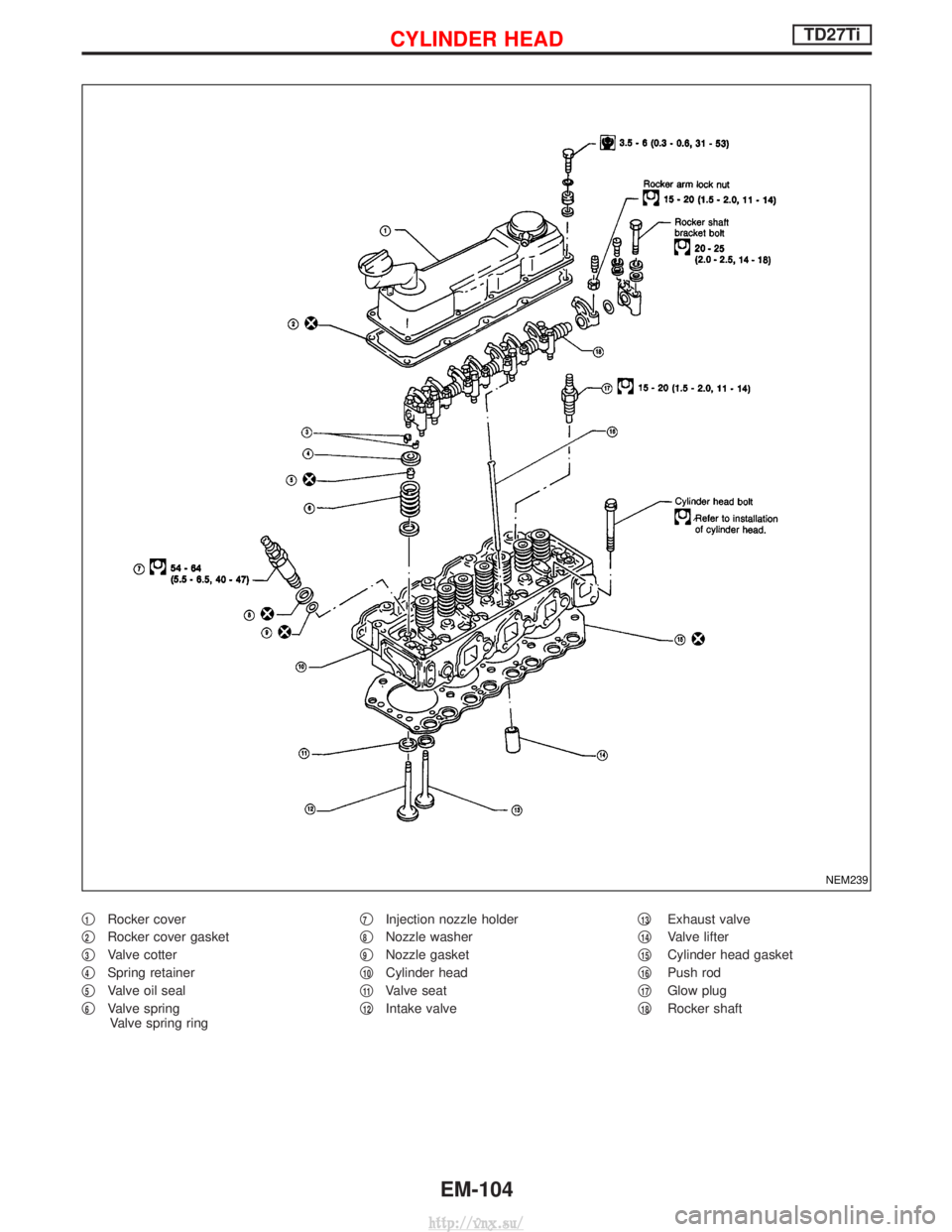
q1Rocker cover
q
2Rocker cover gasket
q
3Valve cotter
q
4Spring retainer
q
5Valve oil seal
q
6Valve spring Valve spring ring q
7Injection nozzle holder
q
8Nozzle washer
q
9Nozzle gasket
q
10Cylinder head
q
11Valve seat
q
12Intake valve q
13Exhaust valve
q
14Valve lifter
q
15Cylinder head gasket
q
16Push rod
q
17Glow plug
q
18Rocker shaft
NEM239
CYLINDER HEADTD27Ti
EM-104
http://vnx.su/
Page 196 of 1833
Removal
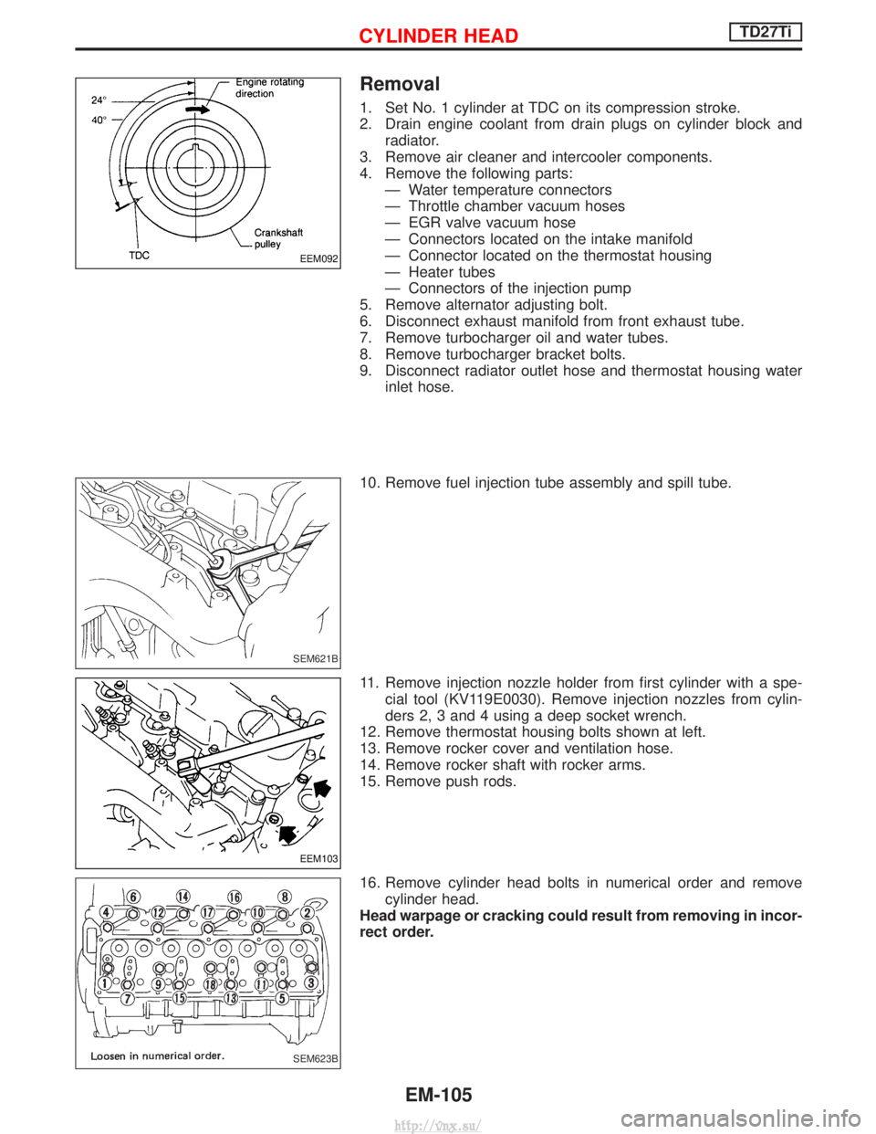
1. Set No. 1 cylinder at TDC on its compression stroke.
2. Drain engine coolant from drain plugs on cylinder block andradiator.
3. Remove air cleaner and intercooler components.
4. Remove the following parts: Ð Water temperature connectors
Ð Throttle chamber vacuum hoses
Ð EGR valve vacuum hose
Ð Connectors located on the intake manifold
Ð Connector located on the thermostat housing
Ð Heater tubes
Ð Connectors of the injection pump
5. Remove alternator adjusting bolt.
6. Disconnect exhaust manifold from front exhaust tube.
7. Remove turbocharger oil and water tubes.
8. Remove turbocharger bracket bolts.
9. Disconnect radiator outlet hose and thermostat housing water inlet hose.
10. Remove fuel injection tube assembly and spill tube.
11. Remove injection nozzle holder from first cylinder with a spe- cial tool (KV119E0030). Remove injection nozzles from cylin-
ders 2, 3 and 4 using a deep socket wrench.
12. Remove thermostat housing bolts shown at left.
13. Remove rocker cover and ventilation hose.
14. Remove rocker shaft with rocker arms.
15. Remove push rods.
16. Remove cylinder head bolts in numerical order and remove cylinder head.
Head warpage or cracking could result from removing in incor-
rect order.
EEM092
SEM621B
EEM103
SEM623B
CYLINDER HEADTD27Ti
EM-105
http://vnx.su/
Page 197 of 1833
Disassembly
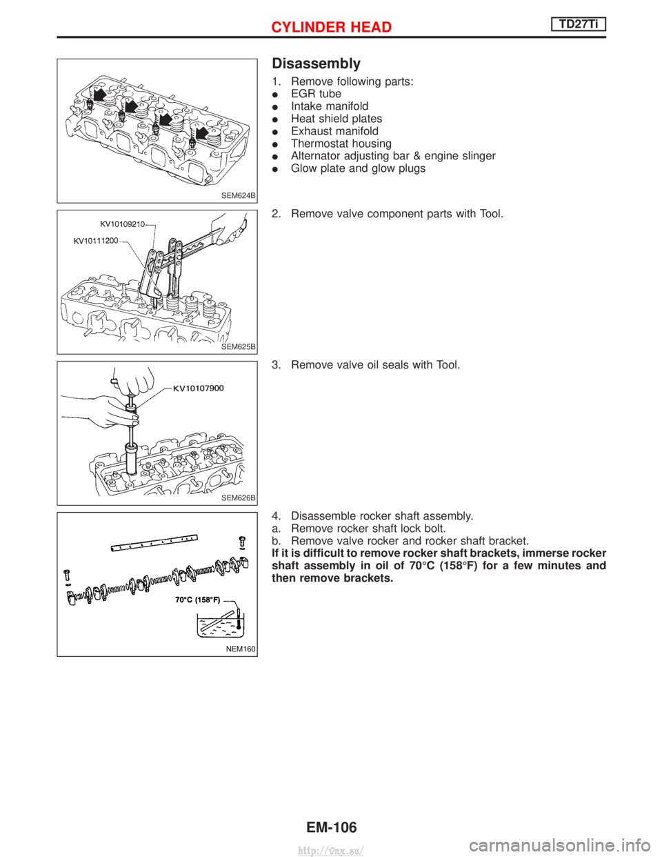
1. Remove following parts:
IEGR tube
I Intake manifold
I Heat shield plates
I Exhaust manifold
I Thermostat housing
I Alternator adjusting bar & engine slinger
I Glow plate and glow plugs
2. Remove valve component parts with Tool.
3. Remove valve oil seals with Tool.
4. Disassemble rocker shaft assembly.
a. Remove rocker shaft lock bolt.
b. Remove valve rocker and rocker shaft bracket.
If it is difficult to remove rocker shaft brackets, immerse rocker
shaft assembly in oil of 70ÉC (158ÉF) for a few minutes and
then remove brackets.
SEM624B
SEM625B
SEM626B
NEM160
CYLINDER HEADTD27Ti
EM-106
http://vnx.su/
Page 198 of 1833
Inspection
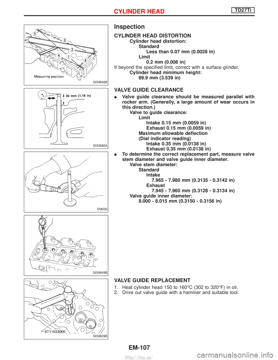
CYLINDER HEAD DISTORTION
Cylinder head distortion:StandardLess than 0.07 mm (0.0028 in)
Limit 0.2 mm (0.008 in)
If beyond the specified limit, correct with a surface grinder. Cylinder head minimum height:89.9 mm (3.539 in)
VALVE GUIDE CLEARANCE
IValve guide clearance should be measured parallel with
rocker arm. (Generally, a large amount of wear occurs in
this direction.)
Valve to guide clearance: LimitIntake 0.15 mm (0.0059 in)
Exhaust 0.15 mm (0.0059 in)
Maximum allowable deflection
(Dial indicator reading) Intake 0.35 mm (0.0138 in)
Exhaust 0.35 mm (0.0138 in)
I To determine the correct replacement part, measure valve
stem diameter and valve guide inner diameter.
Valve stem diameter: StandardIntake7.965 - 7.980 mm (0.3135 - 0.3142 in)
Exhaust 7.945 - 7.960 mm (0.3128 - 0.3134 in)
Valve guide inner diameter: 8.000 - 8.015 mm (0.3150 - 0.3156 in)
VALVE GUIDE REPLACEMENT
1. Heat cylinder head 150 to 160ÉC (302 to 320ÉF) in oil.
2. Drive out valve guide with a hammer and suitable tool.
SEM648B
SEM586A
EM030
SEM649B
SEM628B
CYLINDER HEADTD27Ti
EM-107
http://vnx.su/
Page 199 of 1833
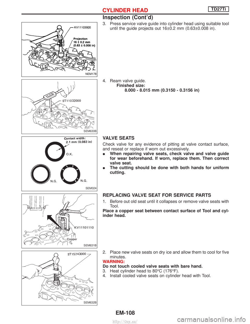
3. Press service valve guide into cylinder head using suitable tooluntil the guide projects out 16 0.2 mm (0.63 0.008 in).
4. Ream valve guide. Finished size:8.000 - 8.015 mm (0.3150 - 0.3156 in)
VALVE SEATS
Check valve for any evidence of pitting at valve contact surface,
and reseat or replace if worn out excessively.
IWhen repairing valve seats, check valve and valve guide
for wear beforehand. If worn, replace them. Then correct
valve seat.
I The cutting should be done with both hands for uniform
cutting.
REPLACING VALVE SEAT FOR SERVICE PARTS
1. Before out old seat until it collapses or remove valve seats with
Tool.
Place a copper seat between contact surface of Tool and cyl-
inder head.
2. Place new valve seats on dry ice and allow them to cool for five minutes.
WARNING:
Do not touch cooled valve seats with bare hand.
3. Heat cylinder head to 80ÉC (176ÉF).
4. Install cooled valve seats on cylinder head with Tool.
NEM178
SEM630B
SEM024
SEM631B
SEM632B
CYLINDER HEADTD27Ti
Inspection (Cont'd)
EM-108
http://vnx.su/
Page 200 of 1833
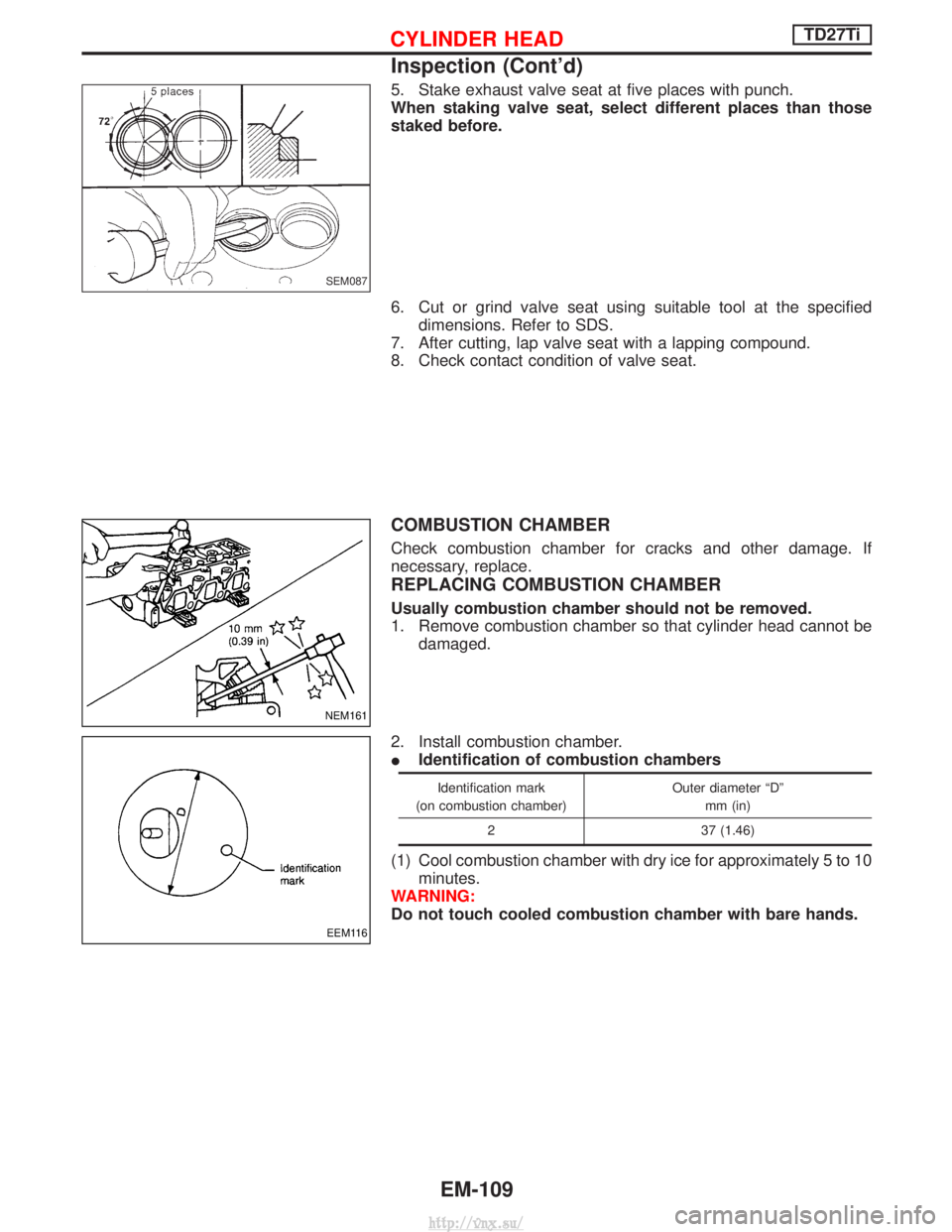
5. Stake exhaust valve seat at five places with punch.
When staking valve seat, select different places than those
staked before.
6. Cut or grind valve seat using suitable tool at the specifieddimensions. Refer to SDS.
7. After cutting, lap valve seat with a lapping compound.
8. Check contact condition of valve seat.
COMBUSTION CHAMBER
Check combustion chamber for cracks and other damage. If
necessary, replace.
REPLACING COMBUSTION CHAMBER
Usually combustion chamber should not be removed.
1. Remove combustion chamber so that cylinder head cannot be damaged.
2. Install combustion chamber.
I Identification of combustion chambers
Identification mark
(on combustion chamber) Outer diameter ªDº
mm (in)
2 37 (1.46)
(1) Cool combustion chamber with dry ice for approximately 5 to 10 minutes.
WARNING:
Do not touch cooled combustion chamber with bare hands.
SEM087
NEM161
EEM116
CYLINDER HEADTD27Ti
Inspection (Cont'd)
EM-109
http://vnx.su/