NISSAN TERRANO 2004 Service Repair Manual
TERRANO 2004
NISSAN
NISSAN
https://www.carmanualsonline.info/img/5/57394/w960_57394-0.png
NISSAN TERRANO 2004 Service Repair Manual
Trending: phone, ad blue, reset, boot, power steering fluid, towing, compression ratio
Page 211 of 1833
Condition 3: Excessively high oil consumption, or exhaust shows pale blue smoke
Probable causeCorrective action
Oil leak at the connection of lubricating oil passage.
ECorrect the connection.
Oil leak at oil seal of turbine.E
Replace turbocharger assembly.Oil leak at oil seal of compressor.E
Worn journal or bearing.E
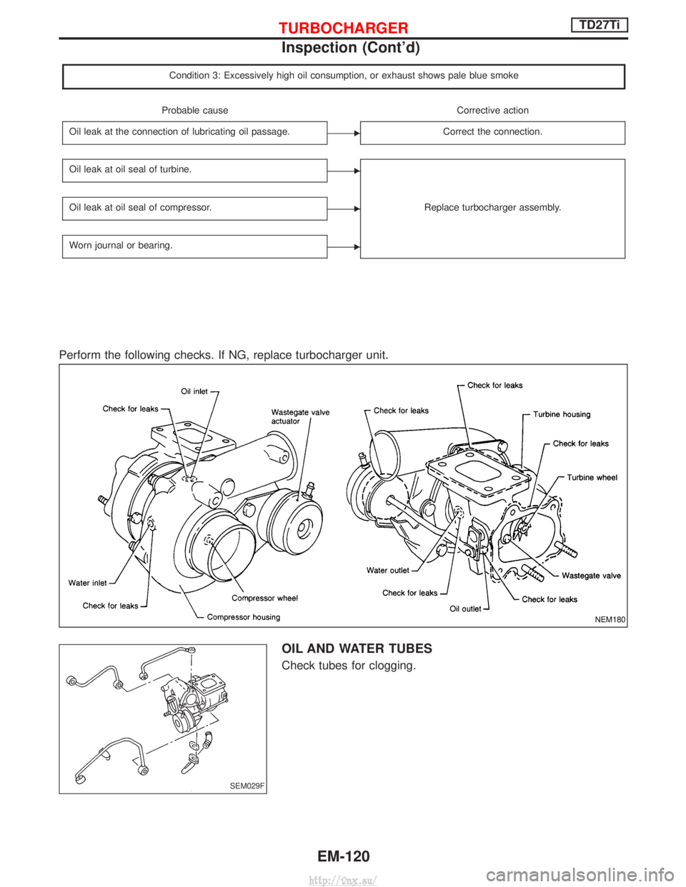
Perform the following checks. If NG, replace turbocharger unit.
OIL AND WATER TUBES
Check tubes for clogging.
NEM180
SEM029F
TURBOCHARGERTD27Ti
Inspection (Cont'd)
EM-120
http://vnx.su/
Page 212 of 1833
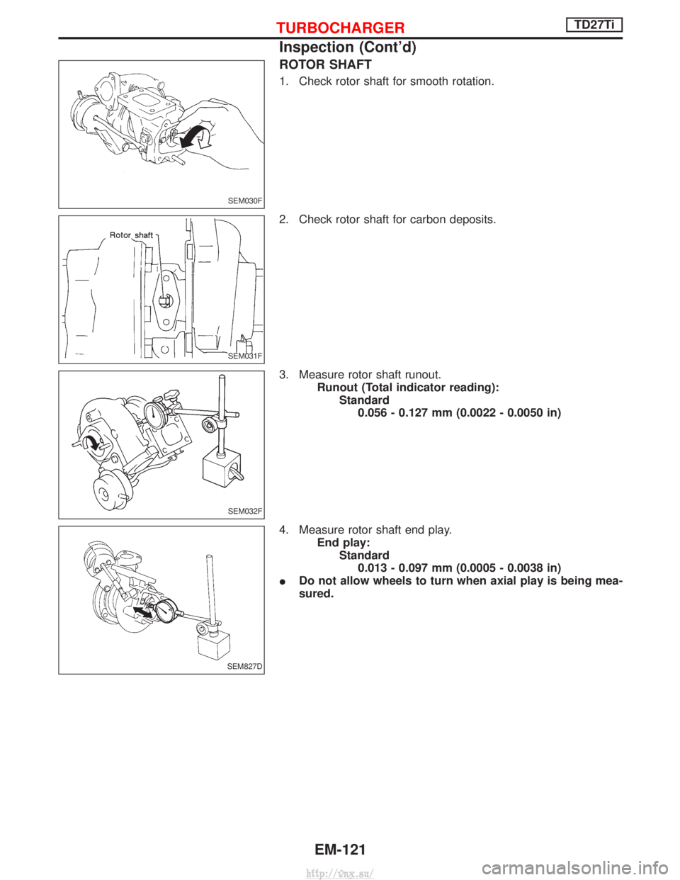
ROTOR SHAFT
1. Check rotor shaft for smooth rotation.
2. Check rotor shaft for carbon deposits.
3. Measure rotor shaft runout.Runout (Total indicator reading):Standard0.056 - 0.127 mm (0.0022 - 0.0050 in)
4. Measure rotor shaft end play. End play:Standard0.013 - 0.097 mm (0.0005 - 0.0038 in)
I Do not allow wheels to turn when axial play is being mea-
sured.
SEM030F
SEM031F
SEM032F
SEM827D
TURBOCHARGERTD27Ti
Inspection (Cont'd)
EM-121
http://vnx.su/
Page 213 of 1833
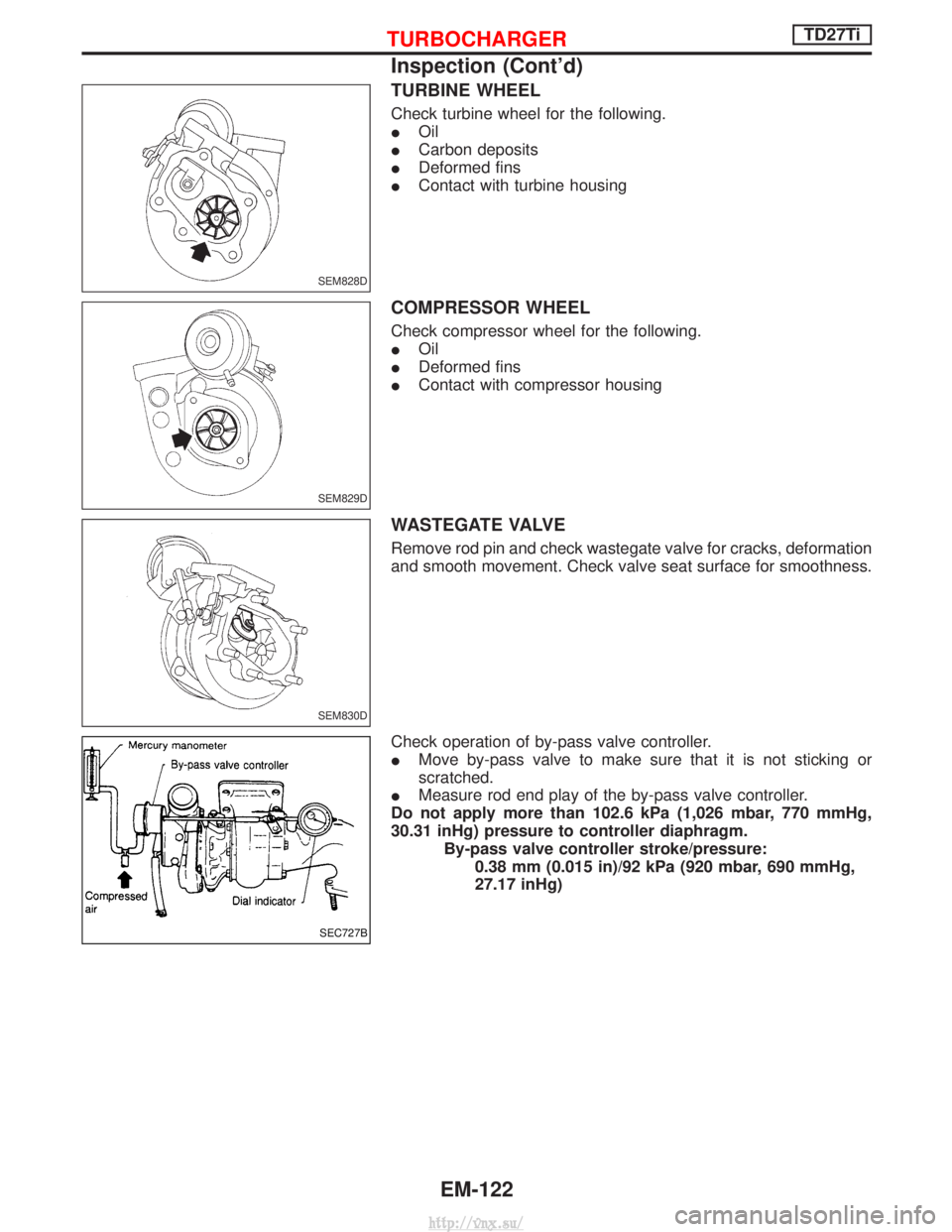
TURBINE WHEEL
Check turbine wheel for the following.
IOil
I Carbon deposits
I Deformed fins
I Contact with turbine housing
COMPRESSOR WHEEL
Check compressor wheel for the following.
IOil
I Deformed fins
I Contact with compressor housing
WASTEGATE VALVE
Remove rod pin and check wastegate valve for cracks, deformation
and smooth movement. Check valve seat surface for smoothness.
Check operation of by-pass valve controller.
IMove by-pass valve to make sure that it is not sticking or
scratched.
I Measure rod end play of the by-pass valve controller.
Do not apply more than 102.6 kPa (1,026 mbar, 770 mmHg,
30.31 inHg) pressure to controller diaphragm. By-pass valve controller stroke/pressure:0.38 mm (0.015 in)/92 kPa (920 mbar, 690 mmHg,
27.17 inHg)
SEM828D
SEM829D
SEM830D
SEC727B
TURBOCHARGERTD27Ti
Inspection (Cont'd)
EM-122
http://vnx.su/
Page 214 of 1833
EEM097E
ENGINE REMOVALTD27Ti
EM-123
http://vnx.su/
Page 215 of 1833
WARNING:
a. Situate vehicle on a flat and solid surface.
b. Place chocks at front and back of rear wheels.
c. Do not remove engine until exhaust system has completelycooled off.
d. For safety during subsequent steps, the tension of wires should be slackened against the engine.
e. Be sure to hoist engine in a safe manner.
f. For engines not equipped with engine slingers, attach proper slingers and bolts described in PARTS CATALOG.
CAUTION:
I When lifting engine, be careful not to strike adjacent parts,
especially, brake lines and brake master cylinder.
I In hoisting the engine, always use engine slingers in a safe
manner.
ENGINE REMOVALTD27Ti
EM-124
http://vnx.su/
Page 216 of 1833
Disassembly
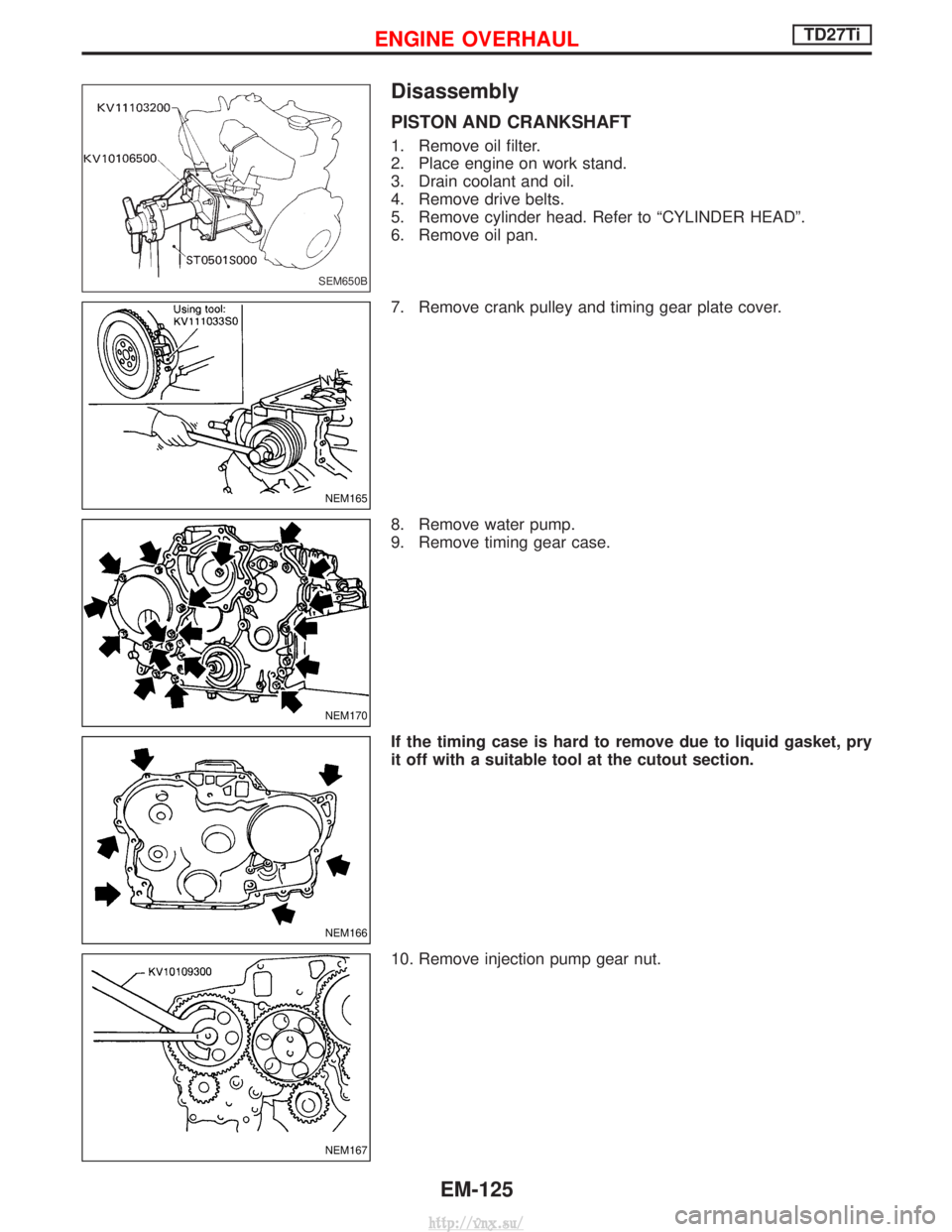
PISTON AND CRANKSHAFT
1. Remove oil filter.
2. Place engine on work stand.
3. Drain coolant and oil.
4. Remove drive belts.
5. Remove cylinder head. Refer to ªCYLINDER HEADº.
6. Remove oil pan.
7. Remove crank pulley and timing gear plate cover.
8. Remove water pump.
9. Remove timing gear case.
If the timing case is hard to remove due to liquid gasket, pry
it off with a suitable tool at the cutout section.
10. Remove injection pump gear nut.
SEM650B
NEM165
NEM170
NEM166
NEM167
ENGINE OVERHAULTD27Ti
EM-125
http://vnx.su/
Page 217 of 1833
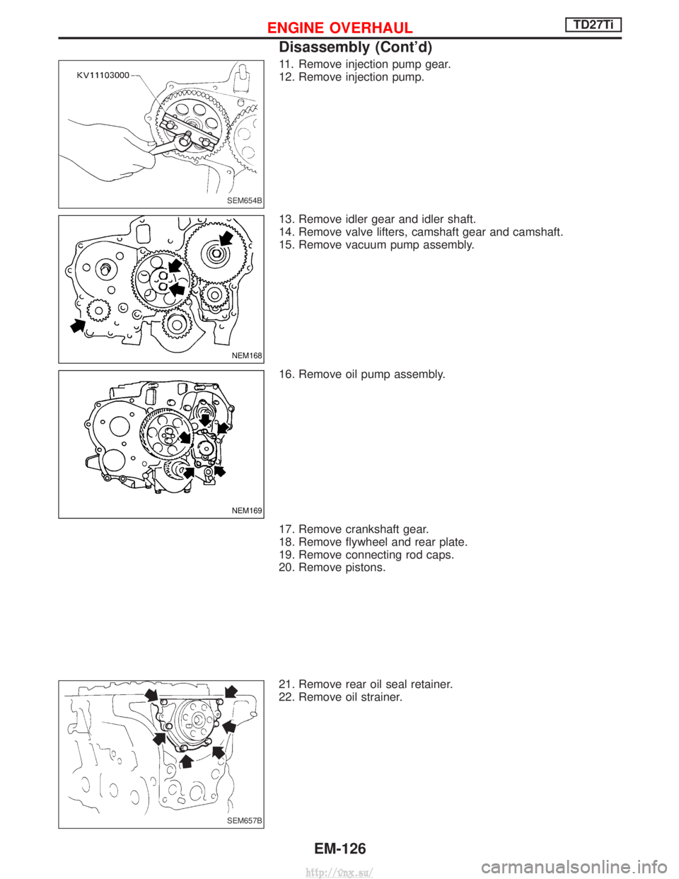
11. Remove injection pump gear.
12. Remove injection pump.
13. Remove idler gear and idler shaft.
14. Remove valve lifters, camshaft gear and camshaft.
15. Remove vacuum pump assembly.
16. Remove oil pump assembly.
17. Remove crankshaft gear.
18. Remove flywheel and rear plate.
19. Remove connecting rod caps.
20. Remove pistons.
21. Remove rear oil seal retainer.
22. Remove oil strainer.
SEM654B
NEM168
NEM169
SEM657B
ENGINE OVERHAULTD27Ti
Disassembly (Cont'd)EM-126
http://vnx.su/
Page 218 of 1833
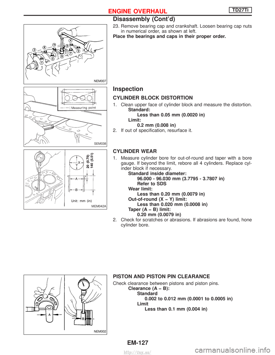
23. Remove bearing cap and crankshaft. Loosen bearing cap nutsin numerical order, as shown at left.
Place the bearings and caps in their proper order.
Inspection
CYLINDER BLOCK DISTORTION
1. Clean upper face of cylinder block and measure the distortion. Standard:Less than 0.05 mm (0.0020 in)
Limit: 0.2 mm (0.008 in)
2. If out of specification, resurface it.
CYLINDER WEAR
1. Measure cylinder bore for out-of-round and taper with a bore gauge. If beyond the limit, rebore all 4 cylinders. Replace cyl-
inder block if necessary.Standard inside diameter: 96.000 - 96.030 mm (3.7795 - 3.7807 in)
Refer to SDS
Wear limit: Less than 0.20 mm (0.0079 in)
Out-of-round (X þ Y) limit: Less than 0.020 mm (0.0008 in)
Taper (A þ B) limit: 0.20 mm (0.0079 in)
2. Check for scratches or abrasions. If abrasions are found, hone cylinder bore.
PISTON AND PISTON PIN CLEARANCE
Check clearance between pistons and piston pins. Clearance (A þ B):Standard0.002 to 0.012 mm (0.0001 to 0.0005 in)
Limit Less than 0.1 mm (0.004 in)
NEM007
SEM038
MEM042A
NEM002
ENGINE OVERHAULTD27Ti
Disassembly (Cont'd)
EM-127
http://vnx.su/
Page 219 of 1833
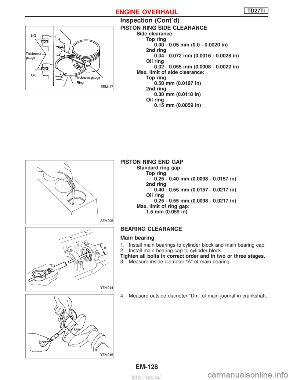
PISTON RING SIDE CLEARANCE
Side clearance:Top ring0.00 - 0.05 mm (0.0 - 0.0020 in)
2nd ring 0.04 - 0.072 mm (0.0016 - 0.0028 in)
Oil ring 0.02 - 0.055 mm (0.0008 - 0.0022 in)
Max. limit of side clearance: Top ring0.50 mm (0.0197 in)
2nd ring 0.30 mm (0.0118 in)
Oil ring 0.15 mm (0.0059 in)
PISTON RING END GAP
Standard ring gap: Top ring0.25 - 0.40 mm (0.0098 - 0.0157 in)
2nd ring 0.40 - 0.55 mm (0.0157 - 0.0217 in)
Oil ring 0.25 - 0.55 mm (0.0098 - 0.0217 in)
Max. limit of ring gap: 1.5 mm (0.059 in)
BEARING CLEARANCE
Main bearing
1. Install main bearings to cylinder block and main bearing cap.
2. Install main bearing cap to cylinder block.
Tighten all bolts in correct order and in two or three stages.
3. Measure inside diameter ªAº of main bearing.
4. Measure outside diameter ªDmº of main journal in crankshaft.
EEM117
SEM905
YEM044
YEM045
ENGINE OVERHAULTD27Ti
Inspection (Cont'd)
EM-128
http://vnx.su/
Page 220 of 1833
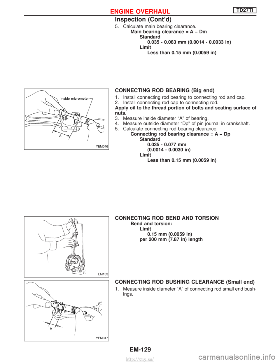
5. Calculate main bearing clearance.Main bearing clearance = A þ DmStandard0.035 - 0.083 mm (0.0014 - 0.0033 in)
Limit Less than 0.15 mm (0.0059 in)
CONNECTING ROD BEARING (Big end)
1. Install connecting rod bearing to connecting rod and cap.
2. Install connecting rod cap to connecting rod.
Apply oil to the thread portion of bolts and seating surface of
nuts.
3. Measure inside diameter ªAº of bearing.
4. Measure outside diameter ªDpº of pin journal in crankshaft.
5. Calculate connecting rod bearing clearance. Connecting rod bearing clearance = A þ DpStandard0.035 - 0.077 mm
(0.0014 - 0.0030 in)
Limit Less than 0.15 mm (0.0059 in)
CONNECTING ROD BEND AND TORSION
Bend and torsion: Limit0.15 mm (0.0059 in)
per 200 mm (7.87 in) length
CONNECTING ROD BUSHING CLEARANCE (Small end)
1. Measure inside diameter ªAº of connecting rod small end bush- ings.
YEM046
EM133
YEM047
ENGINE OVERHAULTD27Ti
Inspection (Cont'd)
EM-129
http://vnx.su/
Trending: check engine, tow bar, speedometer, wiper blades, trunk, glow plug, width
