NISSAN TERRANO 2004 Service Repair Manual
Manufacturer: NISSAN, Model Year: 2004, Model line: TERRANO, Model: NISSAN TERRANO 2004Pages: 1833, PDF Size: 53.42 MB
Page 241 of 1833
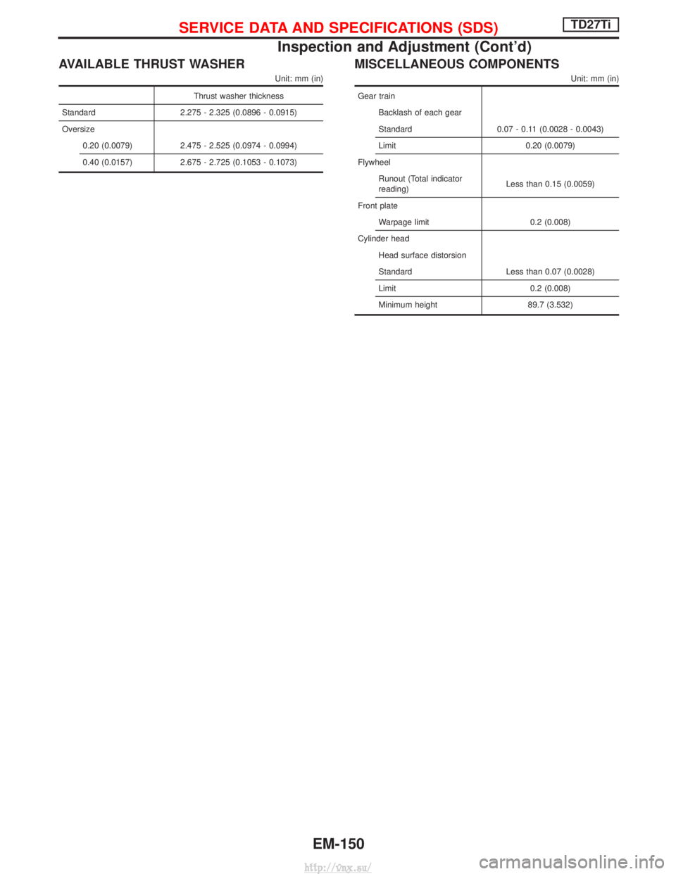
AVAILABLE THRUST WASHER
Unit: mm (in)
Thrust washer thickness
Standard 2.275 - 2.325 (0.0896 - 0.0915)
Oversize 0.20 (0.0079) 2.475 - 2.525 (0.0974 - 0.0994)
0.40 (0.0157) 2.675 - 2.725 (0.1053 - 0.1073)
MISCELLANEOUS COMPONENTS
Unit: mm (in)
Gear trainBacklash of each gear
Standard 0.07 - 0.11 (0.0028 - 0.0043)
Limit 0.20 (0.0079)
Flywheel Runout (Total indicator
reading) Less than 0.15 (0.0059)
Front plate Warpage limit 0.2 (0.008)
Cylinder head Head surface distorsion
Standard Less than 0.07 (0.0028)
Limit 0.2 (0.008)
Minimum height 89.7 (3.532)
SERVICE DATA AND SPECIFICATIONS (SDS)TD27Ti
Inspection and Adjustment (Cont'd)
EM-150
http://vnx.su/
Page 242 of 1833
ENGINE LUBRICATION &COOLING SYSTEMS
SECTION
LC
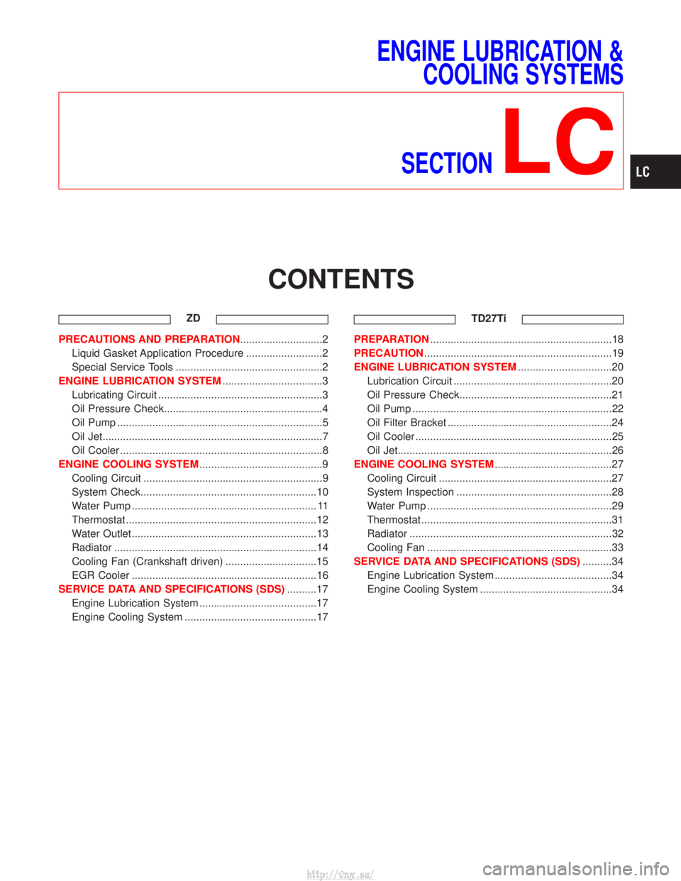
CONTENTS
ZD
PRECAUTIONS AND PREPARATION ............................2
Liquid Gasket Application Procedure ..........................2
Special Service Tools ..................................................2
ENGINE LUBRICATION SYSTEM ..................................3
Lubricating Circuit ........................................................3
Oil Pressure Check......................................................4
Oil Pump ......................................................................5
Oil Jet........................................................................\
...7
Oil Cooler .....................................................................8
ENGINE COOLING SYSTEM ..........................................9
Cooling Circuit .............................................................9
System Check............................................................10
Water Pump ............................................................... 11
Thermostat .................................................................12
Water Outlet ...............................................................13
Radiator .....................................................................14
Cooling Fan (Crankshaft driven) ...............................15
EGR Cooler ...............................................................16
SERVICE DATA AND SPECIFICATIONS (SDS) ..........17
Engine Lubrication System ........................................17
Engine Cooling System .............................................17 TD27TiPREPARATION
..............................................................18
PRECAUTION ................................................................19
ENGINE LUBRICATION SYSTEM ................................20
Lubrication Circuit ......................................................20
Oil Pressure Check....................................................21
Oil Pump ....................................................................22
Oil Filter Bracket ........................................................24
Oil Cooler ...................................................................25
Oil Jet........................................................................\
.26
ENGINE COOLING SYSTEM ........................................27
Cooling Circuit ...........................................................27
System Inspection .....................................................28
Water Pump ...............................................................29
Thermostat .................................................................31
Radiator .....................................................................32
Cooling Fan ...............................................................33
SERVICE DATA AND SPECIFICATIONS (SDS) ..........34
Engine Lubrication System ........................................34
Engine Cooling System .............................................34
http://vnx.su/
Page 243 of 1833
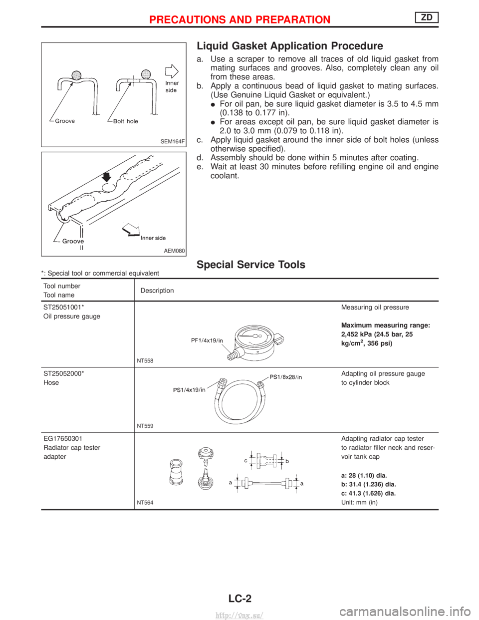
Liquid Gasket Application Procedure
a. Use a scraper to remove all traces of old liquid gasket frommating surfaces and grooves. Also, completely clean any oil
from these areas.
b. Apply a continuous bead of liquid gasket to mating surfaces. (Use Genuine Liquid Gasket or equivalent.)
IFor oil pan, be sure liquid gasket diameter is 3.5 to 4.5 mm
(0.138 to 0.177 in).
I For areas except oil pan, be sure liquid gasket diameter is
2.0 to 3.0 mm (0.079 to 0.118 in).
c. Apply liquid gasket around the inner side of bolt holes (unless otherwise specified).
d. Assembly should be done within 5 minutes after coating.
e. Wait at least 30 minutes before refilling engine oil and engine coolant.
Special Service Tools*: Special tool or commercial equivalent
Tool number
Tool name Description
ST25051001*
Oil pressure gauge
NT558
Measuring oil pressure
Maximum measuring range:
2,452 kPa (24.5 bar, 25
kg/cm
2, 356 psi)
ST25052000*
Hose
NT559
Adapting oil pressure gauge
to cylinder block
EG17650301
Radiator cap tester
adapter
NT564
Adapting radiator cap tester
to radiator filler neck and reser-
voir tank cap
a: 28 (1.10) dia.
b: 31.4 (1.236) dia.
c: 41.3 (1.626) dia.
Unit: mm (in)
SEM164F
AEM080
PRECAUTIONS AND PREPARATIONZD
LC-2
http://vnx.su/
Page 244 of 1833
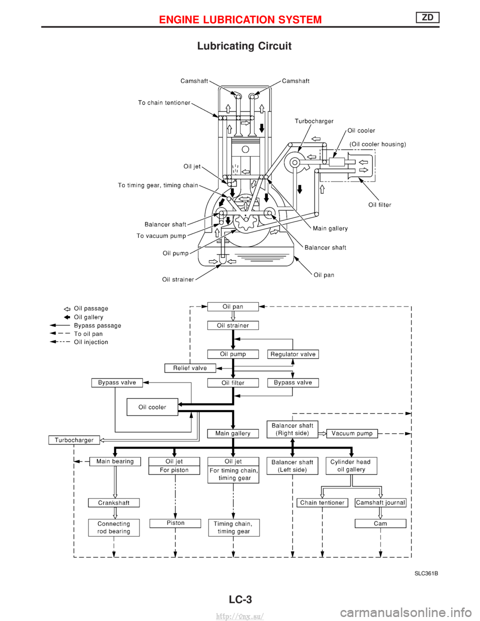
Lubricating Circuit
SLC361B
ENGINE LUBRICATION SYSTEMZD
LC-3
http://vnx.su/
Page 245 of 1833
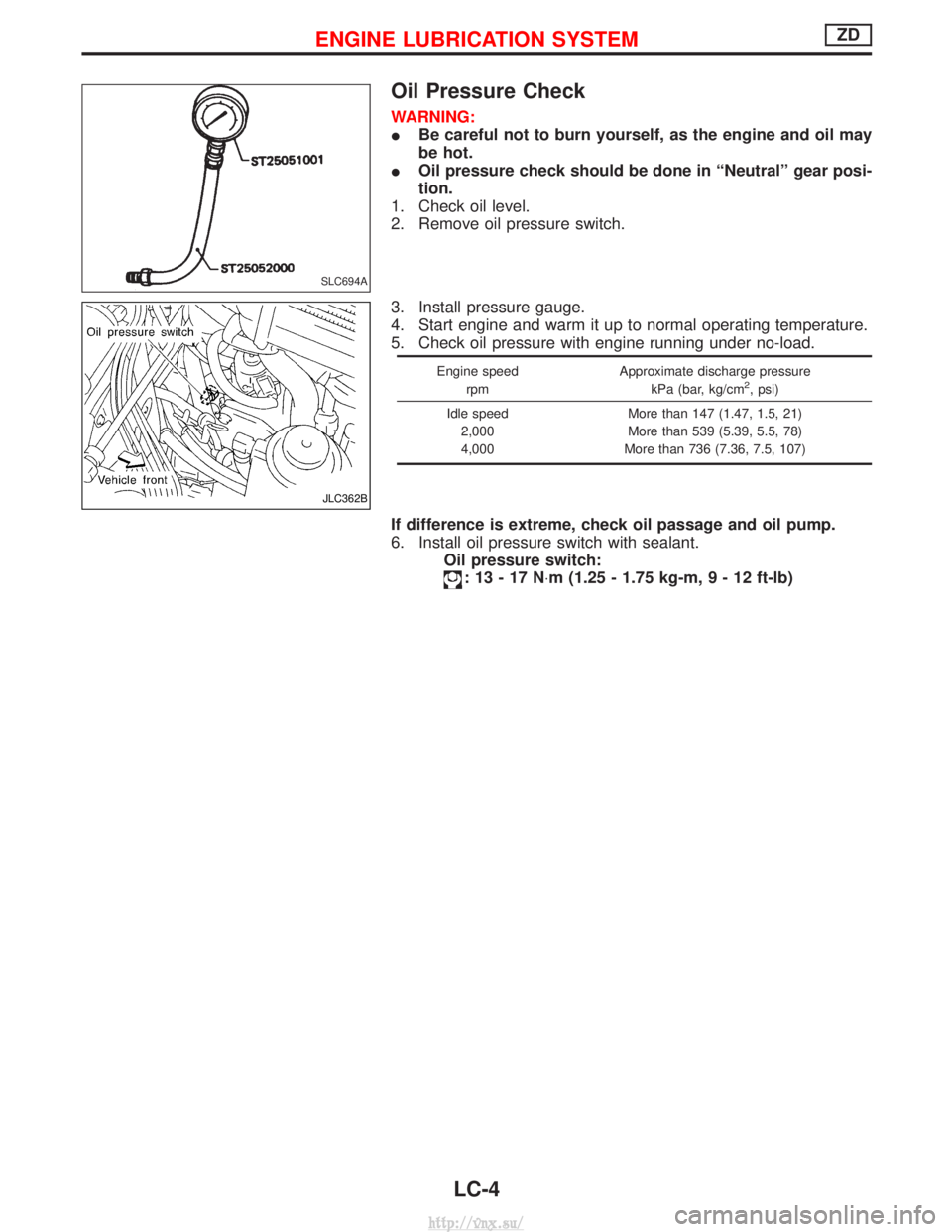
Oil Pressure Check
WARNING:
IBe careful not to burn yourself, as the engine and oil may
be hot.
I Oil pressure check should be done in ªNeutralº gear posi-
tion.
1. Check oil level.
2. Remove oil pressure switch.
3. Install pressure gauge.
4. Start engine and warm it up to normal operating temperature.
5. Check oil pressure with engine running under no-load.
Engine speed
rpm Approximate discharge pressure
kPa (bar, kg/cm2, psi)
Idle speed 2,000
4,000 More than 147 (1.47, 1.5, 21)
More than 539 (5.39, 5.5, 78)
More than 736 (7.36, 7.5, 107)
If difference is extreme, check oil passage and oil pump.
6. Install oil pressure switch with sealant. Oil pressure switch:
:13-17N ×m (1.25 - 1.75 kg-m ,9-12ft-lb)
SLC694A
JLC362B
ENGINE LUBRICATION SYSTEMZD
LC-4
http://vnx.su/
Page 246 of 1833
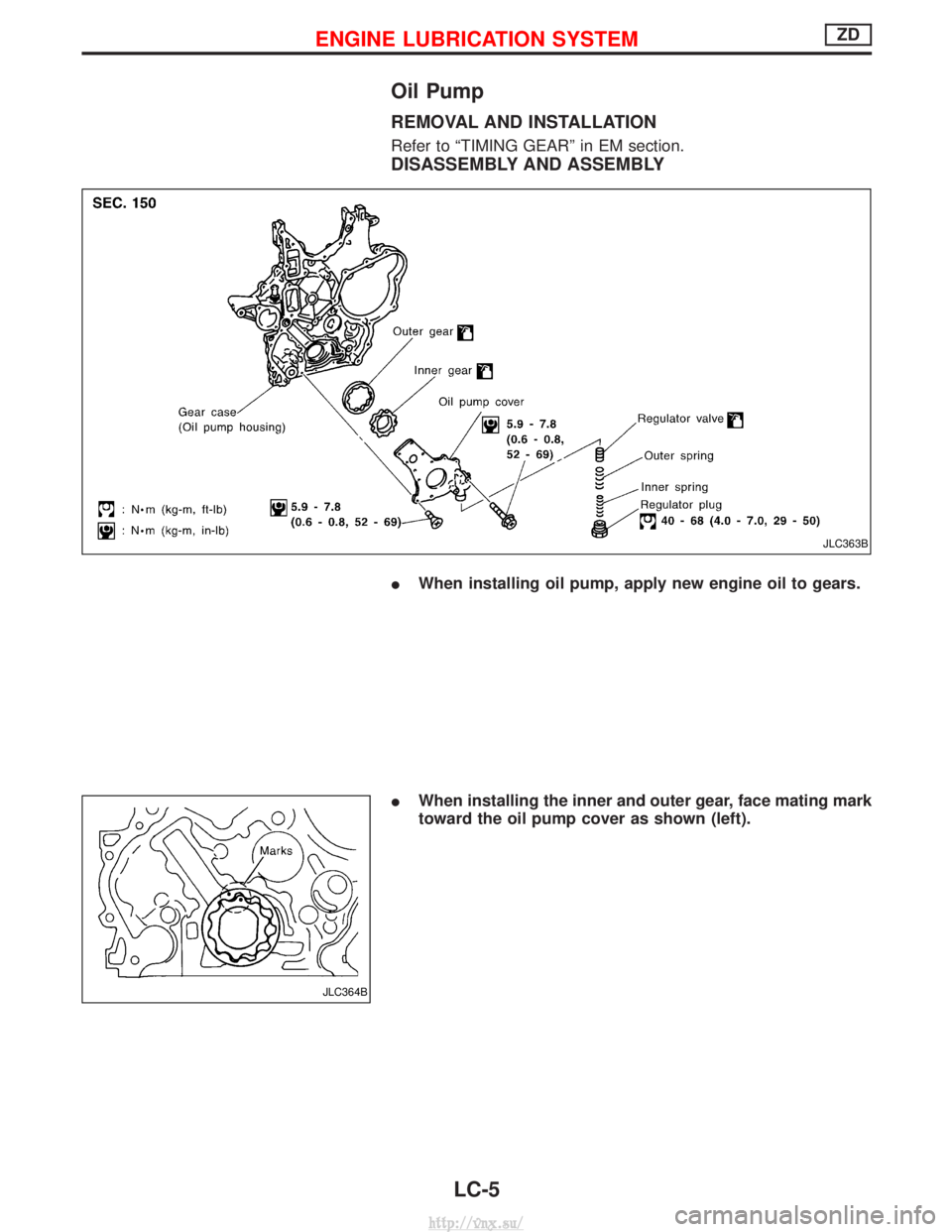
Oil Pump
REMOVAL AND INSTALLATION
Refer to ªTIMING GEARº in EM section.
DISASSEMBLY AND ASSEMBLY
IWhen installing oil pump, apply new engine oil to gears.
I When installing the inner and outer gear, face mating mark
toward the oil pump cover as shown (left).
JLC363B
JLC364B
ENGINE LUBRICATION SYSTEMZD
LC-5
http://vnx.su/
Page 247 of 1833
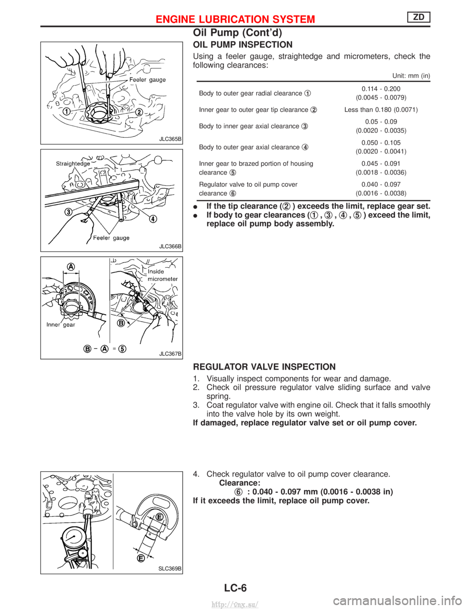
OIL PUMP INSPECTION
Using a feeler gauge, straightedge and micrometers, check the
following clearances:
Unit: mm (in)
Body to outer gear radial clearanceq10.114 - 0.200
(0.0045 - 0.0079)
Inner gear to outer gear tip clearance q
2Less than 0.180 (0.0071)
Body to inner gear axial clearance q
30.05 - 0.09
(0.0020 - 0.0035)
Body to outer gear axial clearance q
40.050 - 0.105
(0.0020 - 0.0041)
Inner gear to brazed portion of housing
clearance q
5
0.045 - 0.091
(0.0018 - 0.0036)
Regulator valve to oil pump cover
clearance q
6
0.040 - 0.097
(0.0016 - 0.0038)
I If the tip clearance ( q2) exceeds the limit, replace gear set.
I If body to gear clearances ( q
1,q3,q4,q5) exceed the limit,
replace oil pump body assembly.
REGULATOR VALVE INSPECTION
1. Visually inspect components for wear and damage.
2. Check oil pressure regulator valve sliding surface and valve spring.
3. Coat regulator valve with engine oil. Check that it falls smoothly into the valve hole by its own weight.
If damaged, replace regulator valve set or oil pump cover.
4. Check regulator valve to oil pump cover clearance. Clearance:q
6: 0.040 - 0.097 mm (0.0016 - 0.0038 in)
If it exceeds the limit, replace oil pump cover.
JLC365B
JLC366B
JLC367B
SLC369B
ENGINE LUBRICATION SYSTEMZD
Oil Pump (Cont'd)
LC-6
http://vnx.su/
Page 248 of 1833
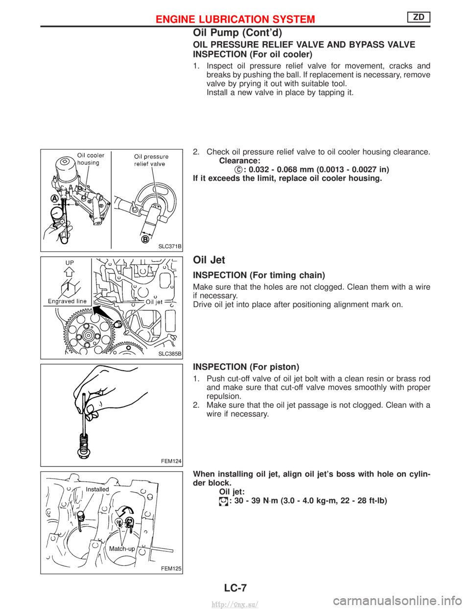
OIL PRESSURE RELIEF VALVE AND BYPASS VALVE
INSPECTION (For oil cooler)
1. Inspect oil pressure relief valve for movement, cracks andbreaks by pushing the ball. If replacement is necessary, remove
valve by prying it out with suitable tool.
Install a new valve in place by tapping it.
2. Check oil pressure relief valve to oil cooler housing clearance. Clearance:q
C: 0.032 - 0.068 mm (0.0013 - 0.0027 in)
If it exceeds the limit, replace oil cooler housing.
Oil Jet
INSPECTION (For timing chain)
Make sure that the holes are not clogged. Clean them with a wire
if necessary.
Drive oil jet into place after positioning alignment mark on.
INSPECTION (For piston)
1. Push cut-off valve of oil jet bolt with a clean resin or brass rod and make sure that cut-off valve moves smoothly with proper
repulsion.
2. Make sure that the oil jet passage is not clogged. Clean with a wire if necessary.
When installing oil jet, align oil jet's boss with hole on cylin-
der block. Oil jet:
:30-39N ×m (3.0 - 4.0 kg-m, 22 - 28 ft-lb)
SLC371B
SLC385B
FEM124
FEM125
ENGINE LUBRICATION SYSTEMZD
Oil Pump (Cont'd)
LC-7
http://vnx.su/
Page 249 of 1833
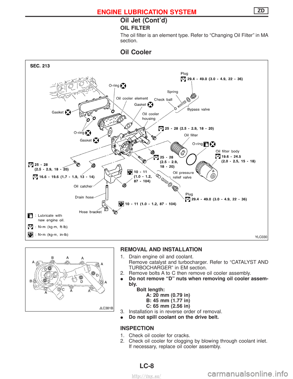
OIL FILTER
The oil filter is an element type. Refer to ªChanging Oil Filterº in MA
section.
Oil Cooler
REMOVAL AND INSTALLATION
1. Drain engine oil and coolant.Remove catalyst and turbocharger. Refer to ªCATALYST AND
TURBOCHARGERº in EM section.
2. Remove bolts A to C then remove oil cooler assembly.
I Do not remove ªDº nuts when removing oil cooler assem-
bly.
Bolt length: A: 20 mm (0.79 in)
B: 45 mm (1.77 in)
C: 65 mm (2.56 in)
3. Installation is in reverse order of removal.
I Do not spill coolant on the drive belt.
INSPECTION
1. Check oil cooler for cracks.
2. Check oil cooler for clogging by blowing through coolant inlet.
If necessary, replace oil cooler assembly.
YLC030
JLC381B
ENGINE LUBRICATION SYSTEMZD
Oil Jet (Cont'd)
LC-8
http://vnx.su/
Page 250 of 1833
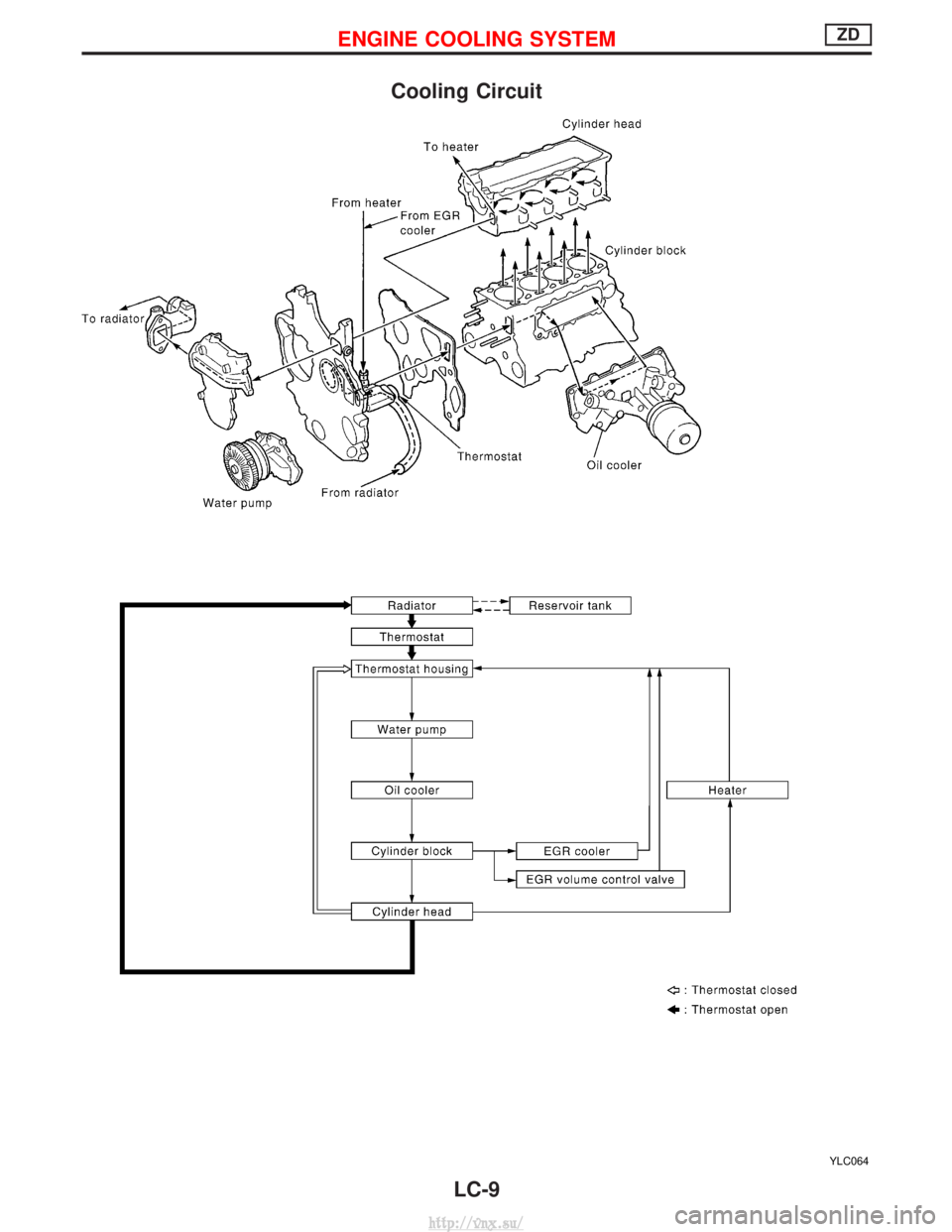
Cooling Circuit
YLC064
ENGINE COOLING SYSTEMZD
LC-9
http://vnx.su/