NISSAN X-TRAIL 2001 Service Repair Manual
Manufacturer: NISSAN, Model Year: 2001, Model line: X-TRAIL, Model: NISSAN X-TRAIL 2001Pages: 3833, PDF Size: 39.49 MB
Page 3421 of 3833
, dis-
charge the refrigerant f")
REFRIGERANT LINES
ATC-145
C
D
E
F
G
H
I
K
L
MA
B
AT C
Removal and Installation for EvaporatorEJS000VG
REMOVAL
1. Using the recycling and recovery equipment (for HFC134a), dis-
charge the refrigerant from A/C system.
2. Disconnect the low-pressure flexible hose and the high-pressure
pipe from the evaporator.
CAUTION:
Cap or wrap the joint of the low-pressure flexible hose and
the high-pressure pipe with a suitable tool such as a vinyl
tape to avoid the entry of air.
3. Remove the cooler grommet cover and cooler grommet.
4. Remove the expansion valve cover and expansion valve.
5. Remove the blower unit.
6. Remove the evaporator cover.
7. Slide the evaporator, then remove it from the heater & cooling
unit.
8. Remove the intake sensor from the evaporator, then remove the
evaporator.
INSTALLATION
CAUTION:
●Replace the O-rings of the low-pressure flexible hose and the high-pressure pipe with new ones,
then apply compressor oil to them when installing them.
●Mark the mounting position of the intake sensor bracket.
RJIA0082E
RJIA0083E
RJIA0084E
RJIA0051E
Page 3422 of 3833
 to dis-
charge the refrigerant.
2. Disconnect the l")
ATC-146
REFRIGERANT LINES
Removal and Installation for Expansion Valve
EJS0028B
1. Use the refrigerant collecting equipment (for HFC-134a) to dis-
charge the refrigerant.
2. Disconnect the low-pressure flexible hose and high-pressure
pipe from the evaporator.
CAUTION:
Cap or wrap the joint of the low-pressure flexible hose and
the high-pressure pipe with a suitable tool such as a vinyl
tape to avoid the entry of air.
3. Remove the expansion valve cover.
4. Remove the expansion valve.
Removal and Installation for Liquid TankEJS0028C
REMOVAL
1. Remove the condenser. Refer to ATC-143, "Removal and Instal-
lation for Condenser" .
2. Remove the liquid tank.
CAUTION:
Cap or wrap the joint of the condenser pipe with a suitable tool
such as a vinyl tape to avoid the entry of air.
INSTALLATION
CAUTION:
●Replace the O-rings of the condenser pipe with new ones, then apply compressor oil to them after
installing them.
●When pouring refrigerant, check for leaks.
Checking for Refrigerant LeaksEJS000VJ
Perform a visual inspection of all refrigeration parts, fittings, hoses and components for signs of A/C lubricant
leakage, damage and corrosion. A/C lubricant leakage may indicate an area of refrigerant leakage. Allow
extra inspection time in these areas when using either an electronic refrigerant leak detector or fluorescent
dye leak detector.
If dye is observed, confirm the leak with an electronic refrigerant leak detector. It is possible a prior leak was
repaired and not properly cleaned.
When searching for leaks, do not stop when one leak is found but continue to check for additional leaks at all
system components and connections.
When searching for refrigerant leaks using an electronic leak detector, move the probe along the suspected
leak area at 1 to 2 inches per second and no further than 1/4 inch from the component.
CAUTION:
Moving the electronic leak detector probe slower and closer to the suspected leak area will improve
the chances of finding a leak.Expansion valve mounting bolts
Tightening torque :3.0 - 4.4 N·m (0.30 - 0.45 kg·m, 26 - 39 in-lb)
RJIA0083E
RJIA0743E
Condenser pipe mounting bolt
Tightening torque :3.5 - 5.9 N·m (0.35 - 0.60 kg·m, 30 - 52 in-lb)
Page 3423 of 3833
")
REFRIGERANT LINES
ATC-147
C
D
E
F
G
H
I
K
L
MA
B
AT C
Checking System for Leaks Using the Fluorescent Leak DetectorEJS000VK
1. Check A/C system for leaks using the UV lamp and safety goggles (J-42220) in a low sunlight area (area
without windows preferable). Illuminate all components, fittings and lines. The dye will appear as a bright
green/yellow area at the point of leakage. Fluorescent dye observed at the evaporator drain opening indi-
cates an evaporator core assembly (tubes, core or expansion valve) leak.
2. If the suspected area is difficult to see, use an adjustable mirror or wipe the area with a clean shop rag or
cloth, with the UV lamp for dye residue.
3. After the leak is repaired, remove any residual dye using dye cleaner (J-43872) to prevent future misdiag-
nosis.
4. Perform a system performance check and verify the leak repair with an approved electronic refrigerant
leak detector.
NOTE:
Other gases in the work area or substances on the A/C components, for example, anti-freeze, windshield
washer fluid, solvents and lubricants, may falsely trigger the leak detector. Make sure the surfaces to be
checked are clean.
Clean with a dry cloth or blow off with shop air.
Do not allow the sensor tip of the detector to contact with any substance. This can also cause false readings
and may damage the detector.
Dye InjectionEJS000VL
(This procedure is only necessary when recharging the system or when the compressor has seized and was
replaced.)
1. Check A/C system static (at rest) pressure. Pressure must be at least 345 kPa (50 psi).
2. Pour one bottle (1/4 ounce / 7.4 cc) of the A/C refrigerant dye into the injector tool (J-41459).
3. Connect the injector tool to the A/C LOW PRESSURE side service fitting.
4. Start engine and switch A/C ON.
5. When the A/C operating (compressor running), inject one bottle (1/4 ounce / 7.4 cc) of fluorescent dye
through the low-pressure service valve using dye injector tool J-41459 (refer to the manufacture's operat-
ing instructions).
6. With the engine still running, disconnect the injector tool from the service fitting.
CAUTION:
Be careful the A/C system or replacing a component, pour the dye directly into the open system con-
nection and proceed with the service procedures.
7. Operate the A/C system for a minimum of 20 minutes to mix the dye with the system oil. Depending on the
leak size, operating conditions and location of the leak, it may take from minutes to days for the dye to
penetrate a leak and become visible.
Electronic Refrigerant Leak DetectorEJS000VM
PRECAUTIONS FOR HANDLING LEAK DETECTOR
When performing a refrigerant leak check, use an A/C leak detector
or equivalent. Ensure that the instrument is calibrated and set prop-
erly per the operating instructions.
The leak detector is a delicate device. In order to use the leak detec-
tor properly, read the operating instructions and perform any speci-
fied maintenance.
SHA705EB
Page 3424 of 3833
 away from point to
be checked.
2. When testing, circle each fitting completely with probe.
3. Move probe along component approx")
ATC-148
REFRIGERANT LINES
1. Position probe approximately 5 mm (3/16 in) away from point to
be checked.
2. When testing, circle each fitting completely with probe.
3. Move probe along component approximately 25 to 50 mm (1 to
2 in)/sec.
CHECKING PROCEDURE
To prevent inaccurate or false readings, make sure there is no refrigerant vapor, shop chemicals, or cigarette
smoke in the vicinity of the vehicle. Perform the leak test in calm area (low air/wind movement) so that the
leaking refrigerant is not dispersed.
1. Turn engine OFF.
2. Connect a suitable A/C manifold gauge set to the A/C service ports.
3. Check if the A/C refrigerant pressure is at least 345 kPa (3.52 kg/cm
2 , 50 psi) above 16°C (61°F). If less
than specification, recover/evacuate and recharge the system with the specified amount of refrigerant.
NOTE:
At temperatures below 16°C (61°F), leaks may not be detected since the system may not reach 345 kPa (3.54
kg/cm
2 , 50 psi).
4. Conduct the leak test from the high side (compressor discharge a to evaporator inlet g) to the low side
(evaporator drain hose h to shaft seal k). Refer to ATC-131, "
Components" \. Perform a leak check for the
following areas carefully. Clean the component to be checked and move the leak detected probe com-
pletely around the connection/component.
Compressor
Check the fitting of high and low pressure hoses, relief valve and shaft seal.
Liquid tank
Check the refrigerant pressure sensor or dual pressure switch.
Service valves
Check all around the service valves. Ensure service valve caps are secured on the service valves (to pre-
vent leaks).
SHA707EA
SHA706E
SHA708EA
Page 3425 of 3833

REFRIGERANT LINES
ATC-149
C
D
E
F
G
H
I
K
L
MA
B
AT C
NOTE:
After removing A/C manifold gauge set from service valves, wipe any residue from valves to prevent any
false readings by leak detector.
Cooling unit (Evaporator)
With engine OFF, turn blower fan on "High" for at least 15 seconds to dissipate any refrigerant trace in the
cooling unit. Wait a minimum of 10 minutes accumulation time (refer to the manufacturer's recommended
procedure for actual wait time) before inserting the leak detector probe into the drain hose.
Keep the probe inserted for at least 10 seconds. Use caution not to contaminate the probe tip with water
or dirt that may be in the drain hose.
5. If a leak detector detects a leak, verify at least once by blowing compressed air into area of suspected
leak, then repeat check as outlined above.
6. Do not stop when one leak is found. Continue to check for additional leaks at all system components.
If no leaks are found, perform steps 7 - 10.
7. Start engine.
8. Set the heater A/C control as follows;
a. A/C switch: ON
b. Face mode
c. Intake position: Recirculation
d. Max cold temperature
e. Fan speed: High
9. Run engine at 1,500 rpm for at least 2 minutes.
10. Turn engine off and perform leak check again following steps 4 through 6 above.
Refrigerant leaks should be checked immediately after stopping the
engine. Begin with the leak detector at the compressor. The pres-
sure on the high pressure side will gradually drop after refrigerant
circulation stops and pressure on the low pressure side will gradually
rise, as shown in the graph. Some leaks are more easily detected
when pressure is high.
11. Before connecting ACR4 to vehicle, check ACR4 gauges. No refrigerant pressure should be displayed. If
pressure is displayed, recover refrigerant from equipment lines and then check refrigerant purity.
12. Discharge A/C system using approved refrigerant recovery equipment. Repair the leaking fitting or com-
ponent as necessary.
13. Evacuate and recharge A/C system and perform the leak test to confirm no refrigerant leaks.
14. Conduct A/C performance test to ensure system works properly.
SHA839E
Page 3426 of 3833
ATC-150
SERVICE DATA AND SPECIFICATIONS (SDS)
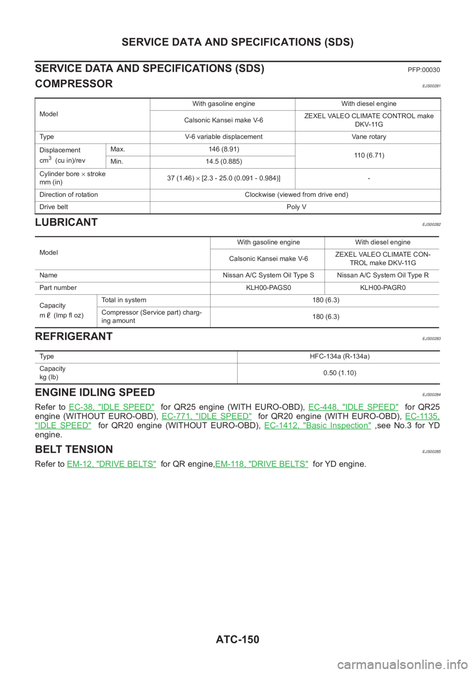
SERVICE DATA AND SPECIFICATIONS (SDS)
PFP:00030
COMPRESSOREJS00281
LUBRICANTEJS00282
REFRIGERANTEJS00283
ENGINE IDLING SPEEDEJS00284
Refer to EC-38, "IDLE SPEED" for QR25 engine (WITH EURO-OBD), EC-448, "IDLE SPEED" for QR25
engine (WITHOUT EURO-OBD), EC-771, "
IDLE SPEED" for QR20 engine (WITH EURO-OBD), EC-1135,
"IDLE SPEED" for QR20 engine (WITHOUT EURO-OBD), EC-1412, "Basic Inspection" ,see No.3 for YD
engine.
BELT TENSIONEJS00285
Refer to EM-12, "DRIVE BELTS" for QR engine,EM-118, "DRIVE BELTS" for YD engine.
ModelWith gasoline engine With diesel engine
Calsonic Kansei make V-6ZEXEL VALEO CLIMATE CONTROL make
DKV-11G
Type V-6 variable displacement Vane rotary
Displacement
cm
3 (cu in)/revMax. 146 (8.91)
110 (6.71)
Min. 14.5 (0.885)
Cylinder bore × stroke
mm (in)37 (1.46) × [2.3 - 25.0 (0.091 - 0.984)] -
Direction of rotation Clockwise (viewed from drive end)
Drive beltPoly V
ModelWith gasoline engine With diesel engine
Calsonic Kansei make V-6ZEXEL VALEO CLIMATE CON-
TROL make DKV-11G
Name Nissan A/C System Oil Type S Nissan A/C System Oil Type R
Part number KLH00-PAGS0 KLH00-PAGR0
Capacity
m (lmp fl oz)Total in system 180 (6.3)
Compressor (Service part) charg-
ing amount180 (6.3)
Ty p eHFC-134a (R-134a)
Capacity
kg (lb)0.50 (1.10)
Page 3427 of 3833

MTC-1
MANUAL AIR CONDITIONER
J AIR CONDITIONER
CONTENTS
C
D
E
F
G
H
I
K
L
M
SECTION
A
B
MTC
MANUAL AIR CONDITIONER
PRECAUTIONS .......................................................... 2
Precautions for Supplemental Restraint System
(SRS) “AIR BAG” and “SEAT BELT PRE-TEN-
SIONER” .................................................................. 2
Wiring Diagrams and Trouble Diagnosis .................. 2
TROUBLE DIAGNOSIS .............................................. 3
How to Perform Trouble Diagnoses for Quick and
Accurate Repair ....................................................... 3
WORK FLOW ........................................................ 3
SYMPTOM TABLE ................................................ 3
Component Parts and Harness Connector Location ..... 4
PASSENGER COMPARTMENT ........................... 4
Discharge Air Flow ................................................... 5
Wiring Diagram-HEATER ......................................... 6
Operational Check ................................................... 7
CHECKING BLOWER ........................................... 7
CHECKING DISCHARGE AIR .............................. 7
CHECKING RECIRCULATION ............................. 7
CHECKING TEMPERATURE DECREASE .......... 8
CHECKING TEMPERATURE INCREASE ............ 8
Mode Door ............................................................... 9
Air Mix Door ........................................................... 10
Intake Door Motor Circuit ........................................ 11
INSPECTION FLOW ............................................ 11
COMPONENT DESCRIPTION ............................ 11
DIAGNOSTIC PROCEDURE .............................. 12
Blower Motor Circuit ............................................... 14
INSPECTION FLOW ........................................... 14
DIAGNOSTIC PROCEDURE .............................. 15
COMPONENT INSPECTION .............................. 17
Insufficient Heating ................................................. 18
INSPECTION FLOW ........................................... 18CONTROLLER .......................................................... 20
Removal and Installation ........................................ 20
Disassembly and Assembly .................................... 20
BLOWER MOTOR .................................................... 21
Removal and Installation ........................................ 21
BLOWER FAN RESISTOR ....................................... 22
Removal and Installation ........................................ 22
INTAKE DOOR MOTOR ........................................... 23
Removal and Installation ........................................ 23
HEATER UNIT ........................................................... 24
Removal and Installation ........................................ 24
REMOVAL ........................................................... 24
INSTALLATION ................................................... 25
Disassembly and Assembly .................................... 25
HEATER CORE ......................................................
... 26
Removal and Installation ........................................ 26
MODE DOOR ............................................................ 27
Control Linkage adjustment .................................... 27
MODE DOOR CONTROL CABLE ....................... 27
AIR MIX DOOR ......................................................... 28
Control Linkage Adjustment ................................... 28
AIR MIX DOOR CONTROL CABLE .................... 28
DUCTS AND GRILLES ............................................. 29
Removal and Installation ........................................ 29
VENTILATOR DUCT, DEFROSTER NOZZLE
AND DEFROSTER DUCTS ................................ 29
CENTER VENTILATOR GRILLE ......................... 29
SIDE VENTILATOR GRILLE ............................... 29
FOOT DUCT ....................................................... 30
FLOOR DUCT ..................................................... 30
Page 3428 of 3833
 “AIR BAG” and “SEAT
BELT PRE-TENSIONER”
EJS0028D
The Supplemental Restraint System such as �")
MTC-2
PRECAUTIONS
PRECAUTIONS
PFP:00001
Precautions for Supplemental Restraint System (SRS) “AIR BAG” and “SEAT
BELT PRE-TENSIONER”
EJS0028D
The Supplemental Restraint System such as “AIR BAG” and “SEAT BELT PRE-TENSIONER”, used along
with a front seat belt, helps to reduce the risk or severity of injury to the driver and front passenger for certain
types of collision. Information necessary to service the system safely is included in the SRS and SB section of
this Service Manual.
WARNING:
●To avoid rendering the SRS inoperative, which could increase the risk of personal injury or death
in the event of a collision which would result in air bag inflation, all maintenance must be per-
formed by an authorized NISSAN/INFINITI dealer.
●Improper maintenance, including incorrect removal and installation of the SRS, can lead to per-
sonal injury caused by unintentional activation of the system. For removal of Spiral Cable and Air
Bag Module, see the SRS section.
●Do not use electrical test equipment on any circuit related to the SRS unless instructed to in this
Service Manual. SRS wiring harnesses can be identified by yellow and/or orange harness connec-
tors.
Wiring Diagrams and Trouble DiagnosisEJS000WA
When you read wiring diagrams, refer to the following:
●GI-13, "How to Read Wiring Diagrams" in GI section.
●PG-3, "Wiring Diagram — POWER —" in EL section.
When you perform trouble diagnosis, refer to the following:
●GI-9, "How to Follow Trouble Diagnoses" in GI section.
●GI-23, "How to Perform Efficient Diagnosis for an Electrical Incident" in GI section.
Page 3429 of 3833

TROUBLE DIAGNOSIS
MTC-3
C
D
E
F
G
H
I
K
L
MA
B
MTC
TROUBLE DIAGNOSISPFP:00004
How to Perform Trouble Diagnoses for Quick and Accurate RepairEJS001FB
WORK FLOW
SYMPTOM TABLE
*1MTC-7, "Operational Check".
SHA900E
Symptom Reference Page
Air outlet does not change. Go to Trouble Diagnosis Procedure for Mode Door.MTC-27
Discharge air temperature does not change. Go to Trouble Diagnosis Procedure Air Mix Door.MTC-28
Intake door does not change.
Go to Trouble Diagnosis Procedure for Intake Door Motor.MTC-11
Intake door motor does not operate normally.
Blower motor operation is malfunctioning. Go to Trouble Diagnosis Procedure for Blower Motor.MTC-14
Insufficient heating. Go to Trouble Diagnosis Procedure for Insufficient Heating.MTC-18
Page 3430 of 3833

MTC-4
TROUBLE DIAGNOSIS
Component Parts and Harness Connector Location
EJS001FC
PASSENGER COMPARTMENT
RJIA0586E