NISSAN X-TRAIL 2003 Electronic Repair Manual
Manufacturer: NISSAN, Model Year: 2003, Model line: X-TRAIL, Model: NISSAN X-TRAIL 2003Pages: 3066, PDF Size: 51.47 MB
Page 2461 of 3066
INTERIOR ROOM LAMP
LT-63
C
D
E
F
G
H
I
J
L
MA
B
LT
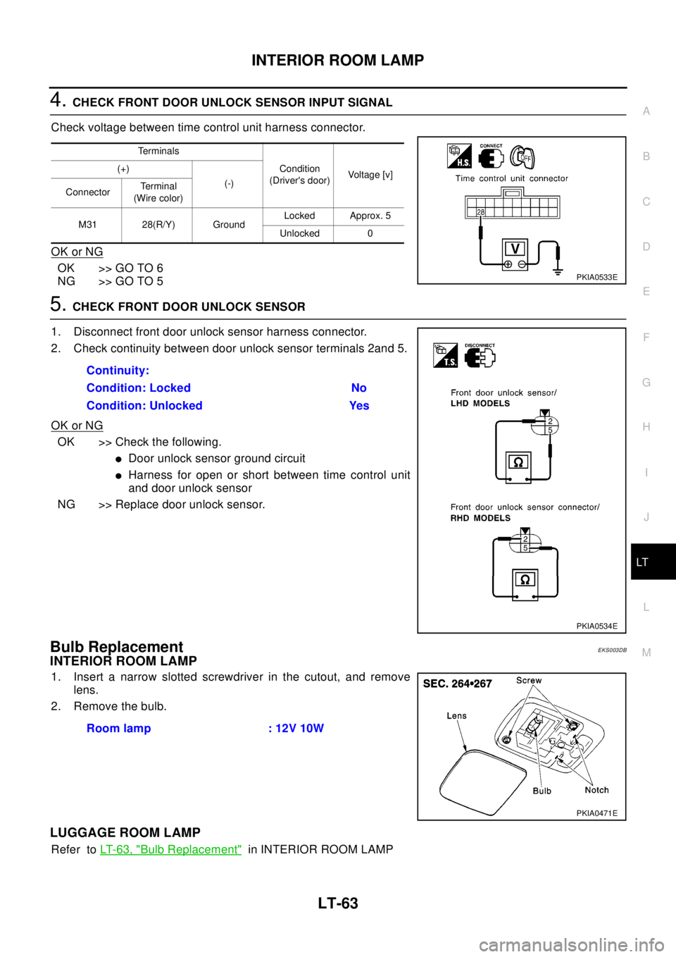
4.CHECK FRONT DOOR UNLOCK SENSOR INPUT SIGNAL
Check voltage between time control unit harness connector.
OK or NG
OK >> GO TO 6
NG >> GO TO 5
5.CHECK FRONT DOOR UNLOCK SENSOR
1. Disconnect front door unlock sensor harness connector.
2. Check continuity between door unlock sensor terminals 2and 5.
OK or NG
OK >> Check the following.
lDoor unlock sensor ground circuit
lHarness for open or short between time control unit
and door unlock sensor
NG >> Replace door unlock sensor.
Bulb ReplacementEKS003DB
INTERIOR ROOM LAMP
1. Insert a narrow slotted screwdriver in the cutout, and remove
lens.
2. Remove the bulb.
LUGGAGE ROOM LAMP
Refer toLT-63, "Bulb Replacement"in INTERIOR ROOM LAMP
Terminals
Condition
(Driver's door)Voltag e [v ] (+)
(-)
ConnectorTerminal
(Wire color)
M31 28(R/Y) GroundLocked Approx. 5
Unlocked 0
PKIA0533E
Continuity:
Condition: Locked No
Condition: Unlocked Yes
PKIA0534E
Room lamp : 12V 10W
PKIA0471E
Page 2462 of 3066
LT-64
INTERIOR ROOM LAMP
Removal and Installation
EKS003DC
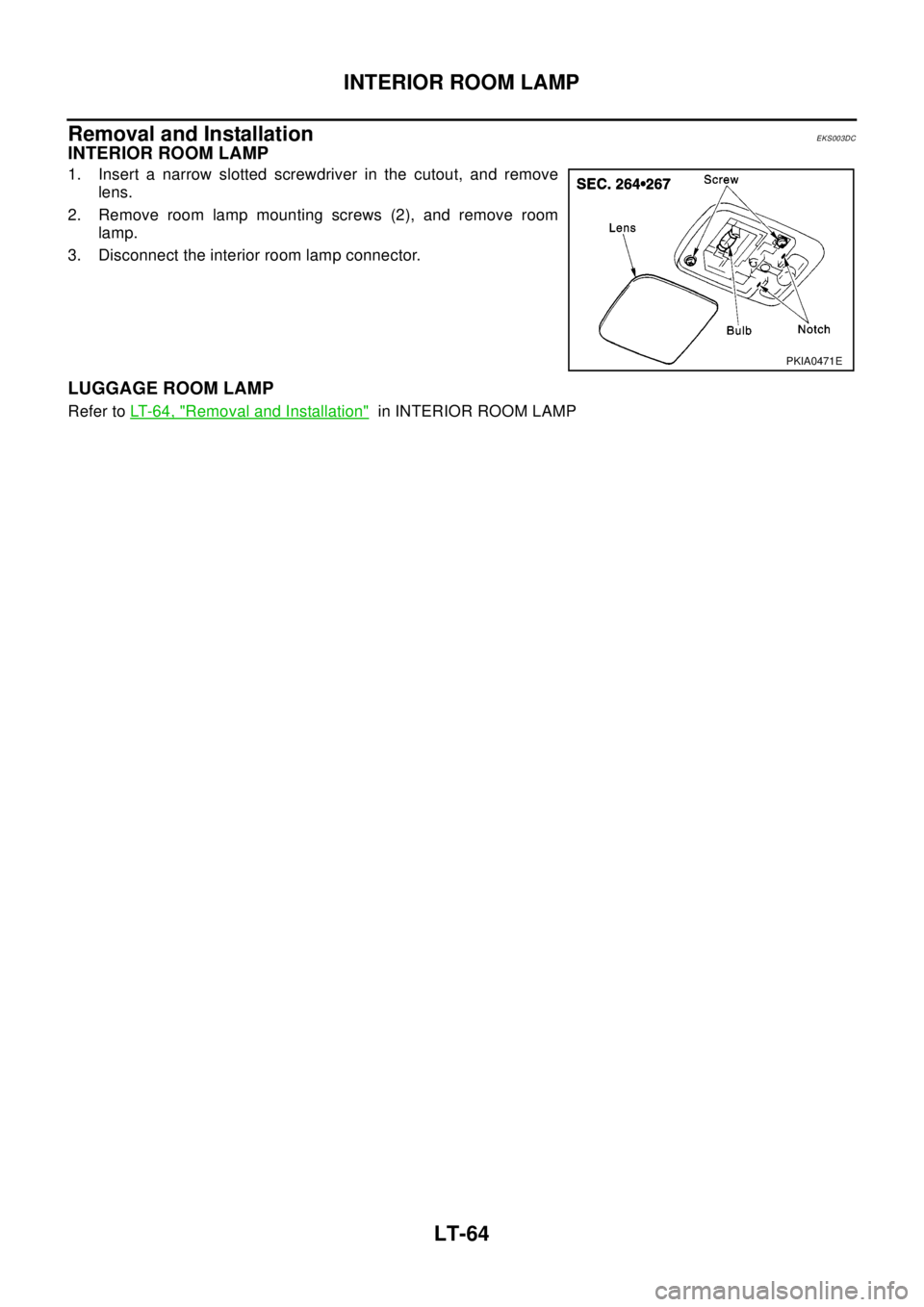
INTERIOR ROOM LAMP
1. Insert a narrow slotted screwdriver in the cutout, and remove
lens.
2. Remove room lamp mounting screws (2), and remove room
lamp.
3. Disconnect the interior room lamp connector.
LUGGAGE ROOM LAMP
Refer toLT- 6 4 , "Removal and Installation"in INTERIOR ROOM LAMP
PKIA0471E
Page 2463 of 3066
SPOT LAMPS
LT-65
C
D
E
F
G
H
I
J
L
MA
B
LT
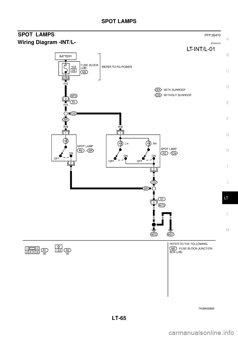
SPOT LAMPSPFP:26470
Wiring Diagram -INT/L-EKS003C8
TKWA0085E
Page 2464 of 3066
LT-66
SPOT LAMPS
Bulb Replacement
EKS003DD
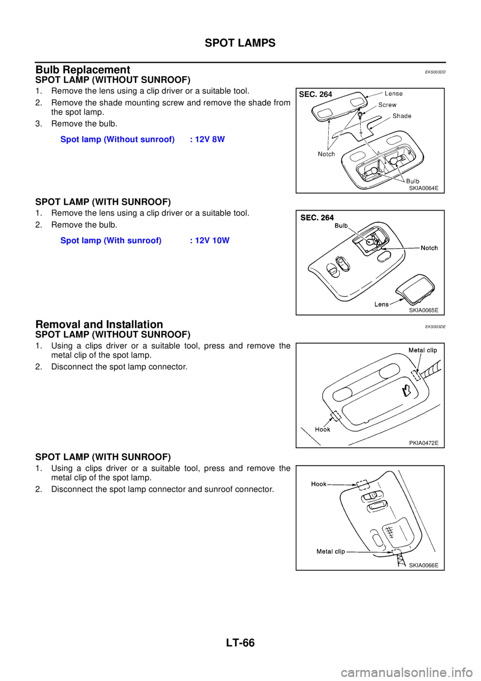
SPOT LAMP (WITHOUT SUNROOF)
1. Remove the lens using a clip driver or a suitable tool.
2. Remove the shade mounting screw and remove the shade from
the spot lamp.
3. Remove the bulb.
SPOT LAMP (WITH SUNROOF)
1. Remove the lens using a clip driver or a suitable tool.
2. Remove the bulb.
Removal and InstallationEKS003DE
SPOT LAMP (WITHOUT SUNROOF)
1. Using a clips driver or a suitable tool, press and remove the
metal clip of the spot lamp.
2. Disconnect the spot lamp connector.
SPOT LAMP (WITH SUNROOF)
1. Using a clips driver or a suitable tool, press and remove the
metal clip of the spot lamp.
2. Disconnect the spot lamp connector and sunroof connector.Spot lamp (Without sunroof) : 12V 8W
SKIA0064E
Spot lamp (With sunroof) : 12V 10W
SKIA0065E
PKIA0472E
SKIA0066E
Page 2465 of 3066

BULB SPECIFICATIONS
LT-67
C
D
E
F
G
H
I
J
L
MA
B
LT
BULB SPECIFICATIONSPFP:26297
HeadlampEKS003GS
Exterior LampEKS003GT
Interior Lamp/IlluminationEKS003GU
Item Wattage (W)
Low/High55 /60(H4)
Item Wattage (W)
Front combination lamp Clearance lamp 5
Front turn signal lamp21(amber)
Side turn signal lamp5
Fog lampFront fog lamp 55(H3)
Rear fog lamp 21
Rear combination lampStop/Tail lamp 21/5
Turn signal lamp 21
Back-up lamp 21
License plate lamp5
High-mounted stop lamp5
Item Wattage (W)
Interior room lamp10
Spot lampWithout sunroof 8
With sunroof 10
Luggage room lamp10
Page 2466 of 3066

LT-68
BULB SPECIFICATIONS
Page 2467 of 3066
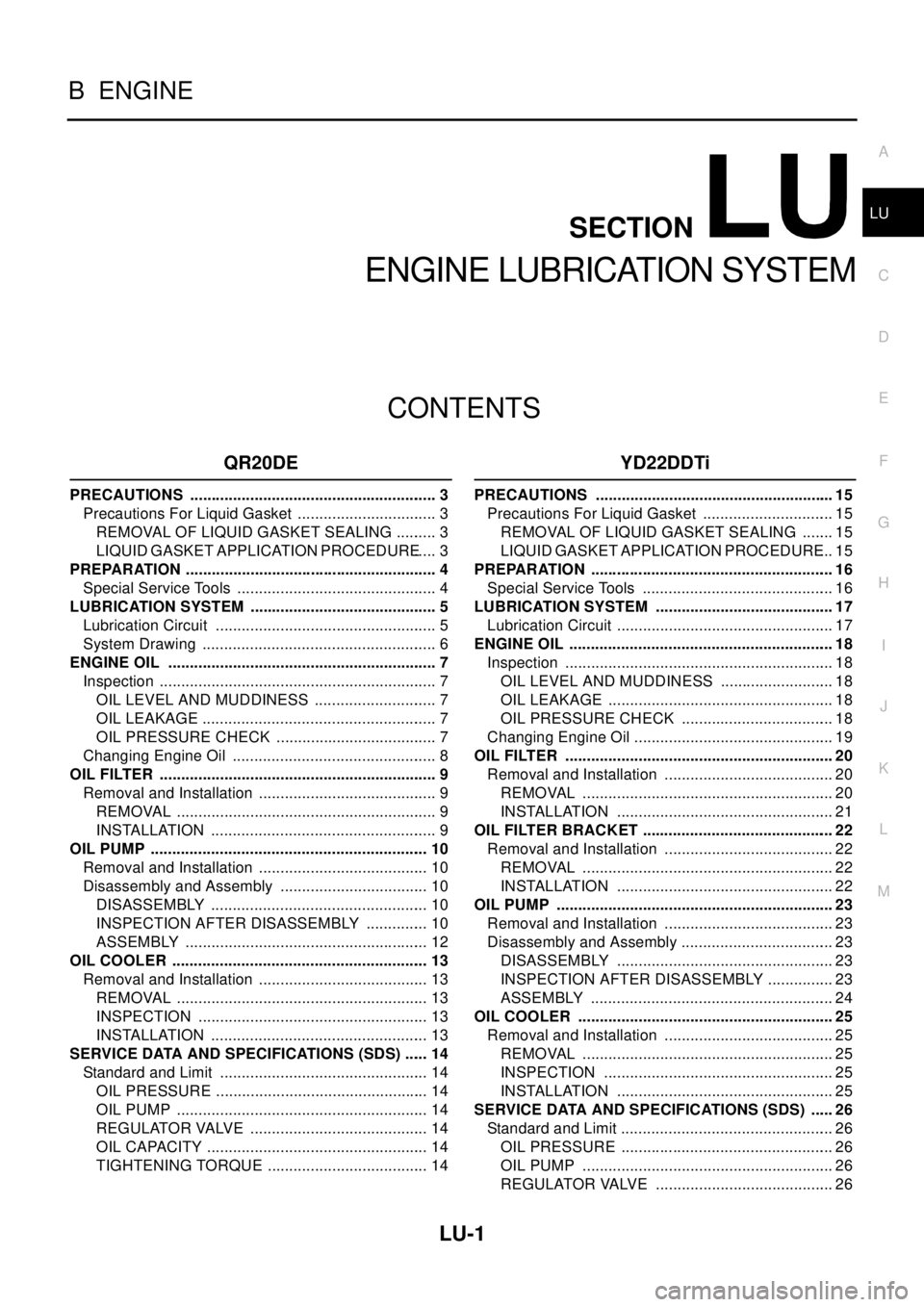
LU-1
ENGINE LUBRICATION SYSTEM
B ENGINE
CONTENTS
C
D
E
F
G
H
I
J
K
L
M
SECTION
A
LU
ENGINE LUBRICATION SYSTEM
QR20DE
PRECAUTIONS .......................................................... 3
Precautions For Liquid Gasket ................................. 3
REMOVAL OF LIQUID GASKET SEALING .......... 3
LIQUID GASKET APPLICATION PROCEDURE..... 3
PREPARATION ........................................................... 4
Special Service Tools ............................................... 4
LUBRICATION SYSTEM ............................................ 5
Lubrication Circuit .................................................... 5
System Drawing ....................................................... 6
ENGINE OIL ............................................................... 7
Inspection ................................................................. 7
OIL LEVEL AND MUDDINESS ............................. 7
OIL LEAKAGE ....................................................... 7
OIL PRESSURE CHECK ...................................... 7
Changing Engine Oil ................................................ 8
OIL FILTER ................................................................. 9
Removal and Installation .......................................... 9
REMOVAL ............................................................. 9
INSTALLATION ..................................................... 9
OIL PUMP ................................................................. 10
Removal and Installation ........................................ 10
Disassembly and Assembly ................................... 10
DISASSEMBLY ................................................... 10
INSPECTION AFTER DISASSEMBLY ............... 10
ASSEMBLY ......................................................... 12
OIL COOLER ............................................................ 13
Removal and Installation ........................................ 13
REMOVAL ........................................................... 13
INSPECTION ...................................................... 13
INSTALLATION ................................................... 13
SERVICE DATA AND SPECIFICATIONS (SDS) ...... 14
Standard and Limit ................................................. 14
OIL PRESSURE .................................................. 14
OIL PUMP ........................................................... 14
REGULATOR VALVE .......................................... 14
OIL CAPACITY .................................................... 14
TIGHTENING TORQUE ...................................... 14
YD22DDTi
PRECAUTIONS ........................................................ 15
Precautions For Liquid Gasket ............................... 15
REMOVAL OF LIQUID GASKET SEALING ........ 15
LIQUID GASKET APPLICATION PROCEDURE... 15
PREPARATION ......................................................... 16
Special Service Tools ............................................. 16
LUBRICATION SYSTEM .......................................... 17
Lubrication Circuit ................................................... 17
ENGINE OIL .............................................................. 18
Inspection ............................................................... 18
OIL LEVEL AND MUDDINESS ........................... 18
OIL LEAKAGE ..................................................... 18
OIL PRESSURE CHECK .................................... 18
Changing Engine Oil ............................................... 19
OIL FILTER ............................................................... 20
Removal and Installation ........................................ 20
REMOVAL ........................................................... 20
INSTALLATION ................................................... 21
OIL FILTER BRACKET ............................................. 22
Removal and Installation ........................................ 22
REMOVAL ........................................................... 22
INSTALLATION ................................................... 22
OIL PUMP ................................................................. 23
Removal and Installation ........................................ 23
Disassembly and Assembly .................................... 23
DISASSEMBLY ................................................... 23
INSPECTION AFTER DISASSEMBLY ................ 23
ASSEMBLY ......................................................... 24
OIL COOLER ............................................................ 25
Removal and Installation ........................................ 25
REMOVAL ........................................................... 25
INSPECTION ...................................................... 25
INSTALLATION ................................................... 25
SERVICE DATA AND SPECIFICATIONS (SDS) ...... 26
Standard and Limit .................................................. 26
OIL PRESSURE .................................................. 26
OIL PUMP ........................................................... 26
REGULATOR VALVE .......................................... 26
Page 2468 of 3066

LU-2
OIL CAPACITY .................................................... 26
Tightening Torque ................................................... 26
Page 2469 of 3066
![NISSAN X-TRAIL 2003 Electronic Repair Manual PRECAUTIONS
LU-3
[QR20DE]
C
D
E
F
G
H
I
J
K
L
MA
LU
[QR20DE]PRECAUTIONSPFP:00001
Precautions For Liquid GasketEBS009SQ
REMOVAL OF LIQUID GASKET SEALING
lAfter removing the mounting bolts and nuts, dis NISSAN X-TRAIL 2003 Electronic Repair Manual PRECAUTIONS
LU-3
[QR20DE]
C
D
E
F
G
H
I
J
K
L
MA
LU
[QR20DE]PRECAUTIONSPFP:00001
Precautions For Liquid GasketEBS009SQ
REMOVAL OF LIQUID GASKET SEALING
lAfter removing the mounting bolts and nuts, dis](/img/5/57402/w960_57402-2468.png)
PRECAUTIONS
LU-3
[QR20DE]
C
D
E
F
G
H
I
J
K
L
MA
LU
[QR20DE]PRECAUTIONSPFP:00001
Precautions For Liquid GasketEBS009SQ
REMOVAL OF LIQUID GASKET SEALING
lAfter removing the mounting bolts and nuts, disconnect and
remove the liquid gasket sealing using a seal cutter.
CAUTION:
Be careful not to damage the mating surfaces.
lIn areas where the cutter is difficult to use, use a plastic hammer
to lightly tap the areas where the liquid gasket is applied.
CAUTION:
If for some unavoidable reason a tool such as a flat-bladed
screwdriver is used, be careful not to damage the mating sur-
faces.
LIQUID GASKET APPLICATION PROCEDURE
1. Using a scraper, remove the old liquid gasket adhering to the
gasket application surface and the mating surface.
lRemove the liquid gasket completely from the groove of the gas-
ket application surface, mounting bolts, and bolt holes.
2. Wipe the gasket application surface and the mating surface with
white gasoline (lighting and heating use) to remove adhering
moisture, grease and foreign materials.
3. Attach the liquid gasket to the tube presser.
Use Genuine Liquid Gasket or equivalent.
4. Apply the gasket without breaks to the specified location with the
specified dimensions.
lIf there is a groove for the liquid gasket application, apply the
gasket to the groove.
lAs for the bolt holes, normally apply the gasket inside the holes.
Occasionally, it should be applied outside the holes. Make sure
to read the text of service manual.
lWithin five minutes of gasket application, install the mating com-
ponent.
lIf the liquid gasket protrudes, wipe it off immediately.
lDo not retighten after the installation.
lAfter 30 minutes or more have passed from the installation, fill
the engine oil and coolant.
CAUTION:
If there are specific instructions in the service manual, observe
them.
PBIC0275E
PBIC0003E
EMA0622D
SEM164F
Page 2470 of 3066
![NISSAN X-TRAIL 2003 Electronic Repair Manual LU-4
[QR20DE]
PREPARATION
PREPARATION
PFP:00002
Special Service ToolsEBS009SR
Tool number
Tool nameDescription
ST25051001
Oil pressure gaugeMeasuring oil pressure
Maximum measuring range:
2,452 kPa (2 NISSAN X-TRAIL 2003 Electronic Repair Manual LU-4
[QR20DE]
PREPARATION
PREPARATION
PFP:00002
Special Service ToolsEBS009SR
Tool number
Tool nameDescription
ST25051001
Oil pressure gaugeMeasuring oil pressure
Maximum measuring range:
2,452 kPa (2](/img/5/57402/w960_57402-2469.png)
LU-4
[QR20DE]
PREPARATION
PREPARATION
PFP:00002
Special Service ToolsEBS009SR
Tool number
Tool nameDescription
ST25051001
Oil pressure gaugeMeasuring oil pressure
Maximum measuring range:
2,452 kPa (25 kg/cm2, 356 psi)
ST25052000
HoseAdapting oil pressure gauge to cylinder block
KV10115801
Oil filter wrenchRemoving oil filter
WS39930000
Tube presserPressing the tube of liquid gasket
S-NT050
S-NT559
S-NT772
S-NT052