NISSAN X-TRAIL 2003 Electronic Repair Manual
X-TRAIL 2003
NISSAN
NISSAN
https://www.carmanualsonline.info/img/5/57402/w960_57402-0.png
NISSAN X-TRAIL 2003 Electronic Repair Manual
Trending: dimensions, fuel cap release, steering wheel adjustment, fuse chart, ignition, instrument panel, wheel torque
Page 2451 of 3066
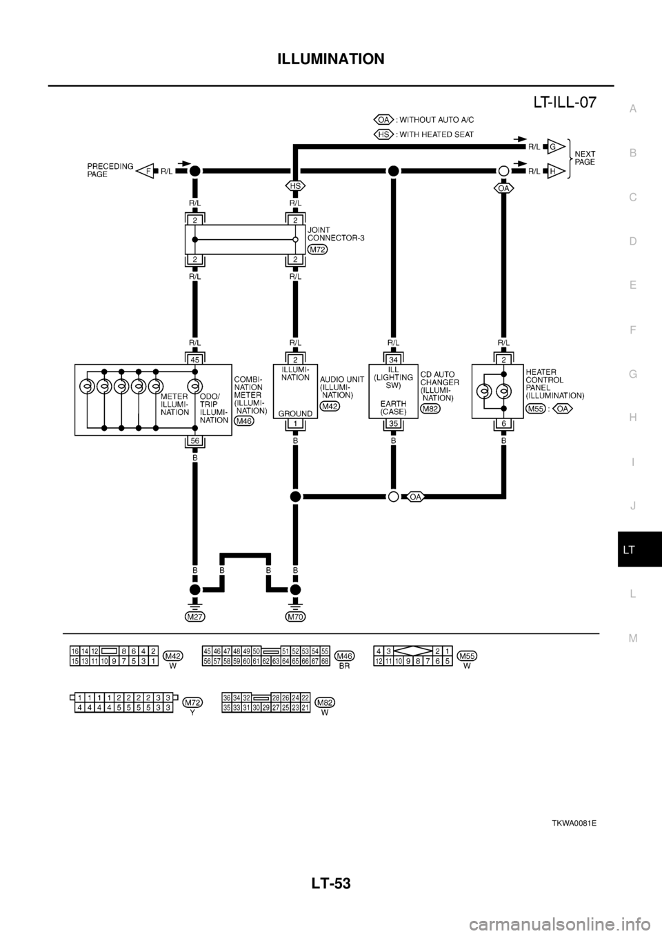
ILLUMINATION
LT-53
C
D
E
F
G
H
I
J
L
MA
B
LT
TKWA0081E
Page 2452 of 3066
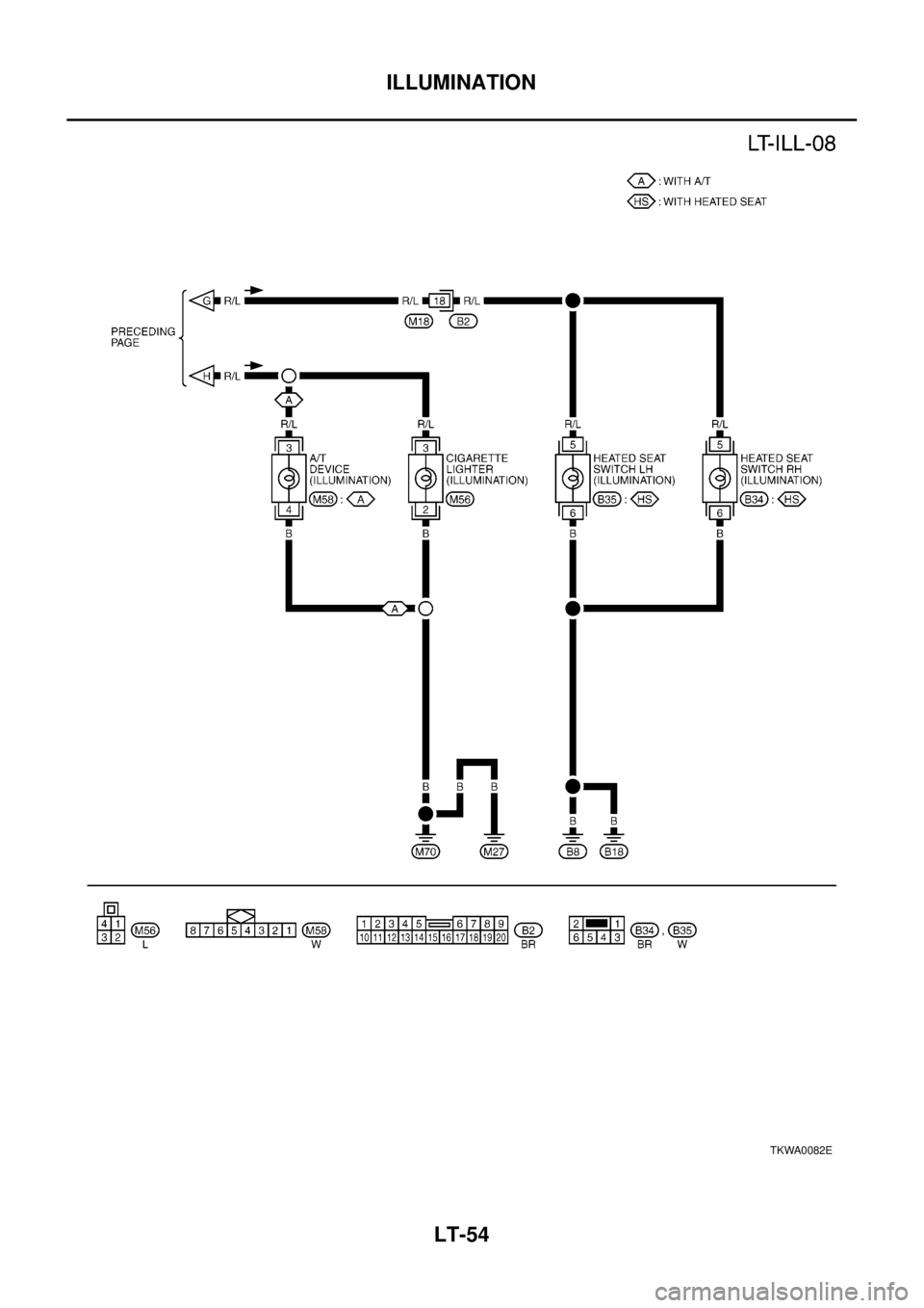
LT-54
ILLUMINATION
TKWA0082E
Page 2453 of 3066

INTERIOR ROOM LAMP
LT-55
C
D
E
F
G
H
I
J
L
MA
B
LT
INTERIOR ROOM LAMPPFP:26410
System DescriptionEKS003BQ
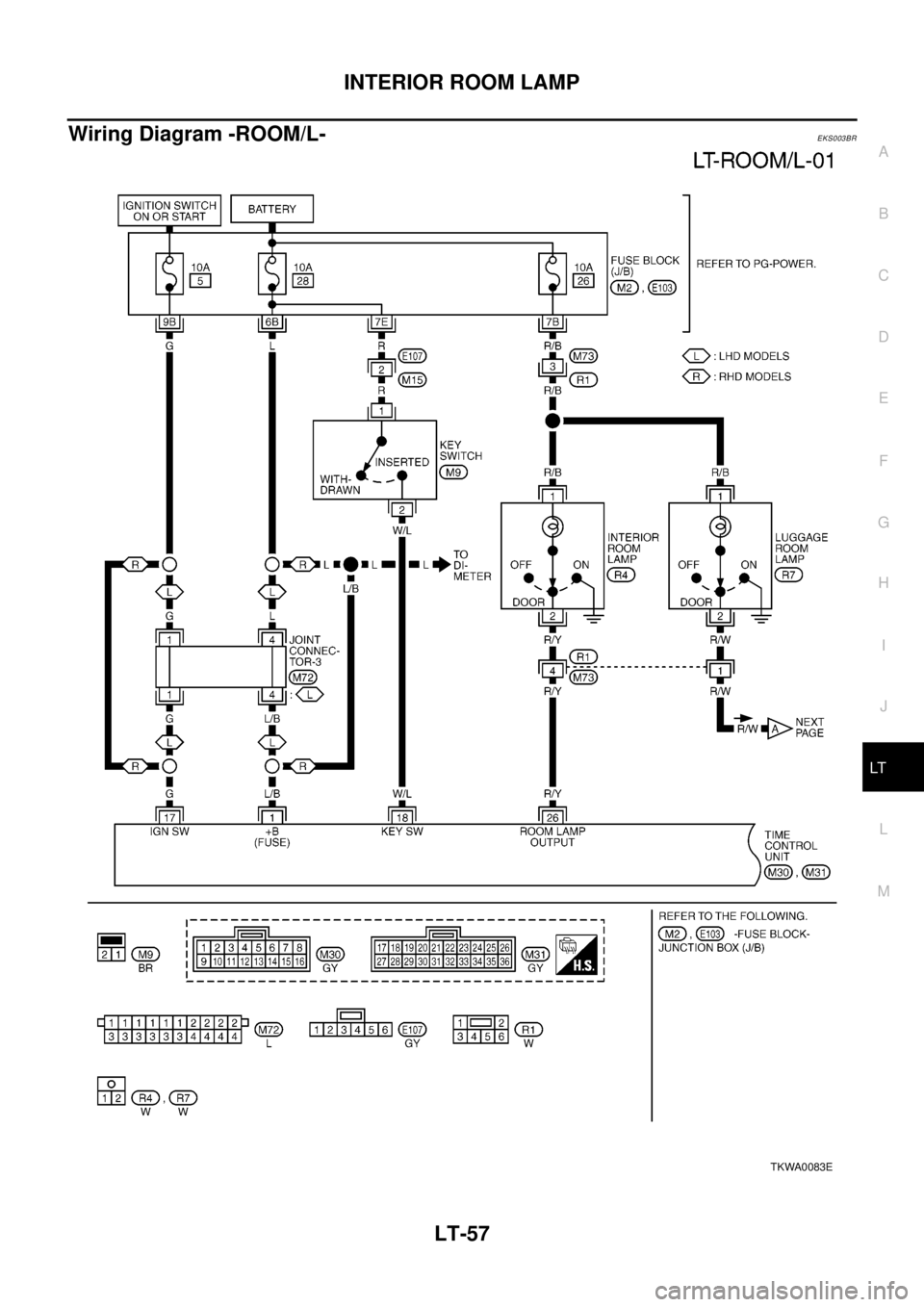
POWER SUPPLY AND GROUND
Power is supplied at all times:
lthrough 10A fuse [No. 28, located in the fuse block (J/B)]
lto key switch terminal 1 and
lto time control unit terminal 1
lthrough 10A fuse [No. 26, located in the fuse block (J/B)]
lto interior room lamp terminal 1.
When the key is removed from ignition key cylinder, power is interrupted:
lthrough key switch terminal 2
lto time control unit terminal 18.
With the ignition key switch in the ON or START position, power is supplied:
lthrough 10A fuse [No. 5, located in the fuse block (J/B)]
lto time control unit terminal 17.
Ground is supplied:
lthrough body grounds terminals M27 and M70
lto time control unit terminal 16
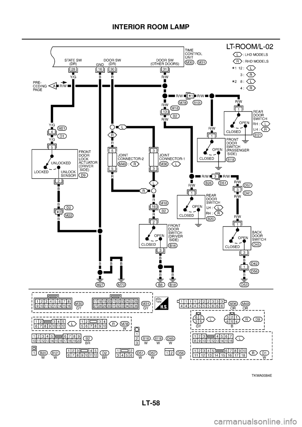
When the driver side door is opened, ground is supplied:
lthrough body grounds B8 and B18
lto door switch driver side terminal 3
lfrom door switch driver side terminal 2
lto time control unit terminal 30.
When any door (except back door) is opened, ground is supplied:
lthroughcasegroundofeachdoorswitch
lto each door switch terminal 1
lto time control unit terminal 31.
When back door is opende, ground is supplied:
lthrough body ground D53
lto back door switch terminal 1
lto time control unit terminal 31.
When the driver side door is unlocked, the time control unit receives a ground signal:
lthrough body grounds terminals M27 and M70
lto door unlock sensor terminal 2
lfrom door unlock sensor terminal 5
lto time control unit terminal 28.
When a signal, or combination of signals is received by the time control unit, ground is supplied:
lthrough time control unit terminal 26
lto interior room lamp terminal 2.
With power and ground supplied, the interior room lamp illuminates.
SWITCH OPERATION
When interior room lamp switch is ON, ground is supplied:
lthrough case grounds of interior room lamp
lto interior room lamp.
INTERIOR ROOM LAMP TIMER OPERATION
When interior room lamp switch is in the “DOOR” position, the time control unit keeps the interior room lamp
illuminated for about 30 seconds when:
Page 2454 of 3066
LT-56
INTERIOR ROOM LAMP
lunlock signal is supplied from driver's door unlock sensor while all doors are closed and key is out of igni-
tion key cylinder
lkey is removed from ignition key cylinder while all doors are closed
ldriver's door is opened and then closed while key is out of the iginition key cylinder. (However, if the
driver's door is closed with the key inserted in the ignition key cylinder after the driver's door is opened
with the key removed, the timer is operated.)
The timer is canceled when:
ldriver's door is locked,
ldriver's door is opened, or
lignition switch is turned ON.
ON-OFF CONTROL
When the driver side door, front passenger door, rear LH or RH door is opened, the interior room lamp turns
on while the interior room lamp switch is in the “DOOR” position.
Page 2455 of 3066
INTERIOR ROOM LAMP
LT-57
C
D
E
F
G
H
I
J
L
MA
B
LT
Wiring Diagram -ROOM/L-EKS003BR
TKWA0083E
Page 2456 of 3066
LT-58
INTERIOR ROOM LAMP
TKWA0084E
Page 2457 of 3066
INTERIOR ROOM LAMP
LT-59
C
D
E
F
G
H
I
J
L
MA
B
LT
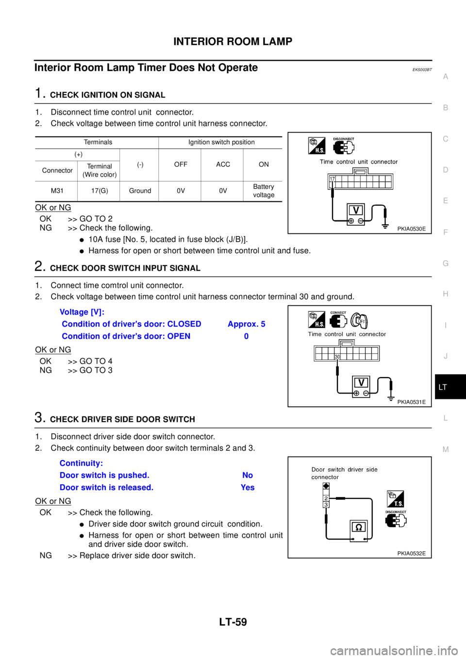
Interior Room Lamp Timer Does Not OperateEKS003BT
1.CHECK IGNITION ON SIGNAL
1. Disconnect time control unit connector.
2. Check voltage between time control unit harness connector.
OK or NG
OK >> GO TO 2
NG >> Check the following.
l10A fuse [No. 5, located in fuse block (J/B)].
lHarness for open or short between time control unit and fuse.
2.CHECK DOOR SWITCH INPUT SIGNAL
1. Connect time comtrol unit connector.
2. Check voltage between time control unit harness connector terminal 30 and ground.
OK or NG
OK >> GO TO 4
NG >> GO TO 3
3.CHECK DRIVER SIDE DOOR SWITCH
1. Disconnect driver side door switch connector.
2. Check continuity between door switch terminals 2 and 3.
OK or NG
OK >> Check the following.
lDriver side door switch ground circuit condition.
lHarness for open or short between time control unit
and driver side door switch.
NG >> Replace driver side door switch.
Terminals Ignition switch position
(+)
(-) OFF ACC ON
ConnectorTe r m i n a l
(Wire color)
M31 17(G) Ground 0V 0VBattery
voltage
PKIA0530E
Vo l ta g e [ V ] :
Condition of driver's door: CLOSED Approx. 5
Condition of driver's door: OPEN 0
PKIA0531E
Continuity:
Door switch is pushed. No
Door switch is released. Yes
PKIA0532E
Page 2458 of 3066
LT-60
INTERIOR ROOM LAMP
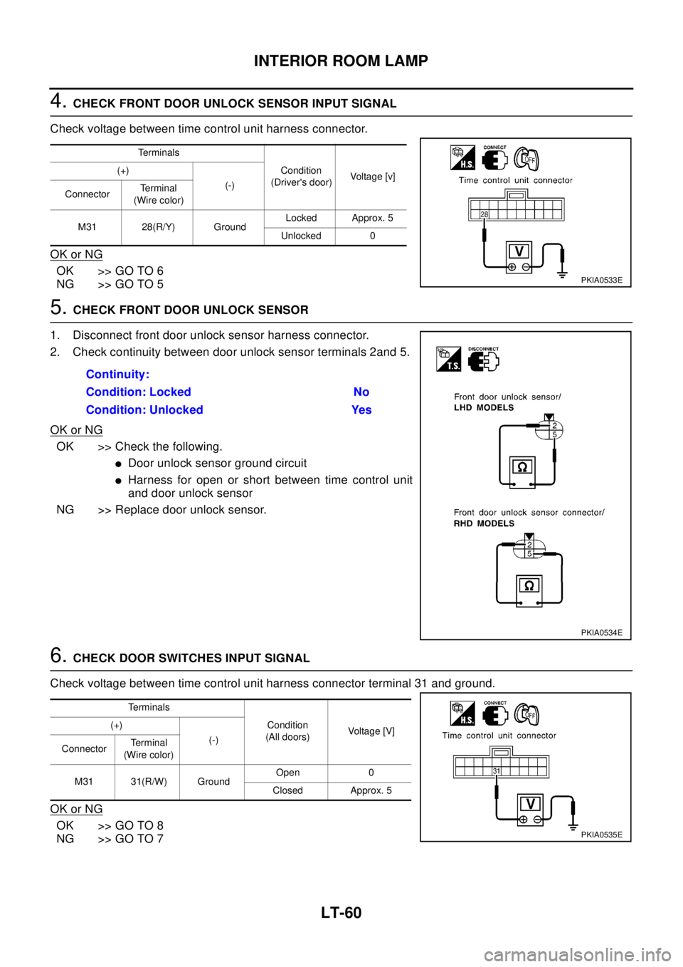
4.CHECK FRONT DOOR UNLOCK SENSOR INPUT SIGNAL
Check voltage between time control unit harness connector.
OK or NG
OK >> GO TO 6
NG >> GO TO 5
5.CHECK FRONT DOOR UNLOCK SENSOR
1. Disconnect front door unlock sensor harness connector.
2. Check continuity between door unlock sensor terminals 2and 5.
OK or NG
OK >> Check the following.
lDoor unlock sensor ground circuit
lHarness for open or short between time control unit
and door unlock sensor
NG >> Replace door unlock sensor.
6.CHECK DOOR SWITCHES INPUT SIGNAL
Check voltage between time control unit harness connector terminal 31 and ground.
OK or NG
OK >> GO TO 8
NG >> GO TO 7
Te r m i n a l s
Condition
(Driver's door)Voltage [v] (+)
(-)
ConnectorTe r m i n a l
(Wire color)
M31 28(R/Y) GroundLocked Approx. 5
Unlocked 0
PKIA0533E
Continuity:
Condition: Locked No
Condition: Unlocked Yes
PKIA0534E
Te r m i n a l s
Condition
(All doors)Voltage [V] (+)
(-)
ConnectorTerminal
(Wire color)
M31 31(R/W) GroundOpen 0
Closed Approx. 5
PKIA0535E
Page 2459 of 3066
INTERIOR ROOM LAMP
LT-61
C
D
E
F
G
H
I
J
L
MA
B
LT
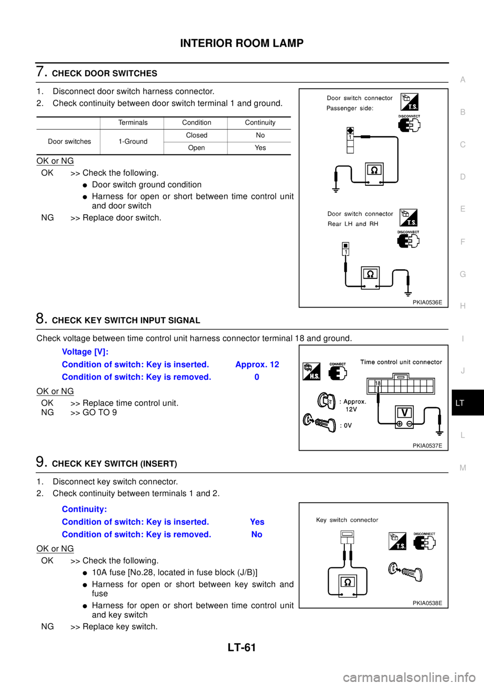
7.CHECK DOOR SWITCHES
1. Disconnect door switch harness connector.
2. Check continuity between door switch terminal 1 and ground.
OK or NG
OK >> Check the following.
lDoor switch ground condition
lHarness for open or short between time control unit
and door switch
NG >> Replace door switch.
8.CHECK KEY SWITCH INPUT SIGNAL
Check voltage between time control unit harness connector terminal 18 and ground.
OK or NG
OK >> Replace time control unit.
NG >> GO TO 9
9.CHECK KEY SWITCH (INSERT)
1. Disconnect key switch connector.
2. Check continuity between terminals 1 and 2.
OK or NG
OK >> Check the following.
l10A fuse [No.28, located in fuse block (J/B)]
lHarness for open or short between key switch and
fuse
lHarness for open or short between time control unit
and key switch
NG >> Replace key switch.
Terminals Condition Continuity
Door switches 1-GroundClosed No
Open Yes
PKIA0536E
Vo l ta g e [ V ] :
Condition of switch: Key is inserted. Approx. 12
Condition of switch: Key is removed. 0
PKIA0537E
Continuity:
Condition of switch: Key is inserted. Yes
Condition of switch: Key is removed. No
PKIA0538E
Page 2460 of 3066
LT-62
INTERIOR ROOM LAMP
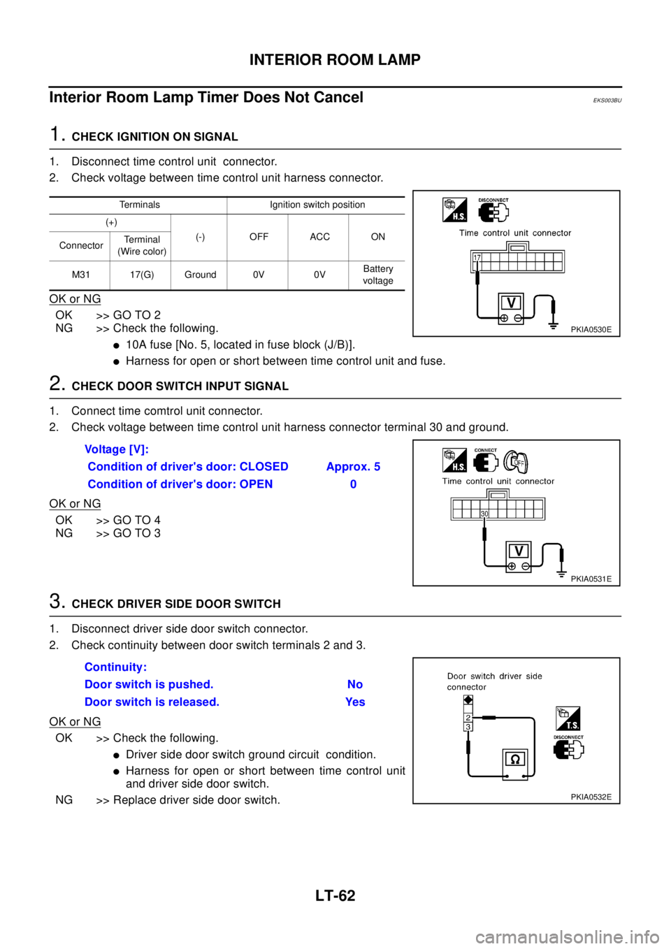
Interior Room Lamp Timer Does Not Cancel
EKS003BU
1.CHECK IGNITION ON SIGNAL
1. Disconnect time control unit connector.
2. Check voltage between time control unit harness connector.
OK or NG
OK >> GO TO 2
NG >> Check the following.
l10A fuse [No. 5, located in fuse block (J/B)].
lHarness for open or short between time control unit and fuse.
2.CHECK DOOR SWITCH INPUT SIGNAL
1. Connect time comtrol unit connector.
2. Check voltage between time control unit harness connector terminal 30 and ground.
OK or NG
OK >> GO TO 4
NG >> GO TO 3
3.CHECK DRIVER SIDE DOOR SWITCH
1. Disconnect driver side door switch connector.
2. Check continuity between door switch terminals 2 and 3.
OK or NG
OK >> Check the following.
lDriver side door switch ground circuit condition.
lHarness for open or short between time control unit
and driver side door switch.
NG >> Replace driver side door switch.
Terminals Ignition switch position
(+)
(-) OFF ACC ON
ConnectorTe r m i n a l
(Wire color)
M31 17(G) Ground 0V 0VBattery
voltage
PKIA0530E
Vo l ta g e [ V ] :
Condition of driver's door: CLOSED Approx. 5
Condition of driver's door: OPEN 0
PKIA0531E
Continuity:
Door switch is pushed. No
Door switch is released. Yes
PKIA0532E
Trending: headlamp, mirror, wheel torque, change key battery, open hood, light, check transmission fluid
