NISSAN X-TRAIL 2003 Electronic Repair Manual
Manufacturer: NISSAN, Model Year: 2003, Model line: X-TRAIL, Model: NISSAN X-TRAIL 2003Pages: 3066, PDF Size: 51.47 MB
Page 2591 of 3066
INPUT SHAFT AND GEARS
MT-55
D
E
F
G
H
I
J
K
L
MA
B
MT
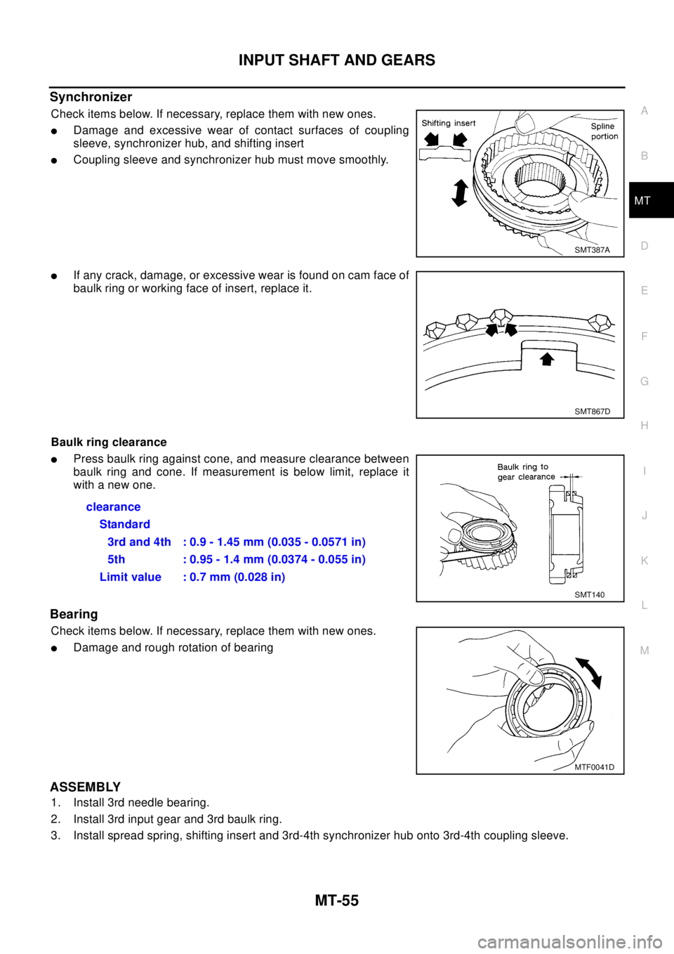
Synchronizer
Check items below. If necessary, replace them with new ones.
lDamage and excessive wear of contact surfaces of coupling
sleeve, synchronizer hub, and shifting insert
lCoupling sleeve and synchronizer hub must move smoothly.
lIf any crack, damage, or excessive wear is found on cam face of
baulk ring or working face of insert, replace it.
Baulk ring clearance
lPress baulk ring against cone, and measure clearance between
baulk ring and cone. If measurement is below limit, replace it
with a new one.
Bearing
Check items below. If necessary, replace them with new ones.
lDamage and rough rotation of bearing
ASSEMBLY
1. Install 3rd needle bearing.
2. Install 3rd input gear and 3rd baulk ring.
3. Install spread spring, shifting insert and 3rd-4th synchronizer hub onto 3rd-4th coupling sleeve.
SMT387A
SMT867D
clearance
Standard
3rd and 4th : 0.9 - 1.45 mm (0.035 - 0.0571 in)
5th : 0.95 - 1.4 mm (0.0374 - 0.055 in)
Limit value : 0.7 mm (0.028 in)
SMT140
MTF0041D
Page 2592 of 3066
MT-56
INPUT SHAFT AND GEARS
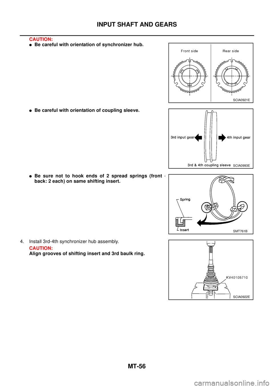
CAUTION:
lBe careful with orientation of synchronizer hub.
lBe careful with orientation of coupling sleeve.
lBe sure not to hook ends of 2 spread springs (front ·
back: 2 each) on same shifting insert.
4. Install 3rd-4th synchronizer hub assembly.
CAUTION:
Align grooves of shifting insert and 3rd baulk ring.
SCIA0921E
SCIA0993E
SMT761B
SCIA0922E
Page 2593 of 3066
INPUT SHAFT AND GEARS
MT-57
D
E
F
G
H
I
J
K
L
MA
B
MT
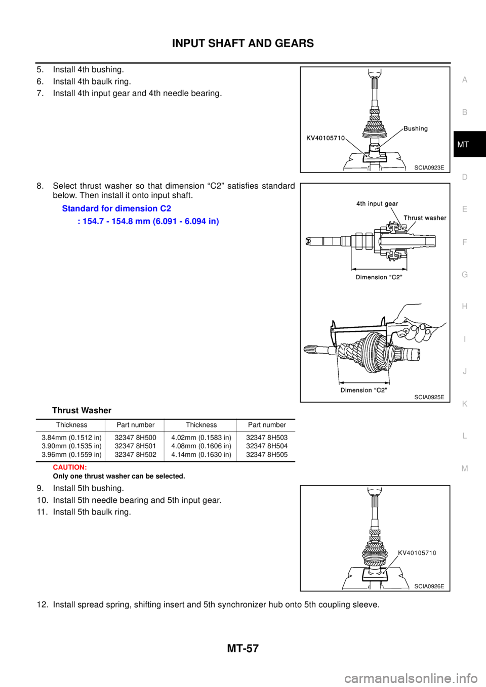
5. Install 4th bushing.
6. Install 4th baulk ring.
7. Install 4th input gear and 4th needle bearing.
8. Select thrust washer so that dimension “C2” satisfies standard
below. Then install it onto input shaft.
Thrust Washer
CAUTION:
Only one thrust washer can be selected.
9. Install 5th bushing.
10. Install 5th needle bearing and 5th input gear.
11. Install 5th baulk ring.
12. Install spread spring, shifting insert and 5th synchronizer hub onto 5th coupling sleeve.
SCIA0923E
Standard for dimension C2
: 154.7 - 154.8 mm (6.091 - 6.094 in)
SCIA0925E
Thickness Part number Thickness Part number
3.84mm (0.1512 in)
3.90mm (0.1535 in)
3.96mm (0.1559 in)32347 8H500
32347 8H501
32347 8H5024.02mm (0.1583 in)
4.08mm (0.1606 in)
4.14mm (0.1630 in)32347 8H503
32347 8H504
32347 8H505
SCIA0926E
Page 2594 of 3066
MT-58
INPUT SHAFT AND GEARS
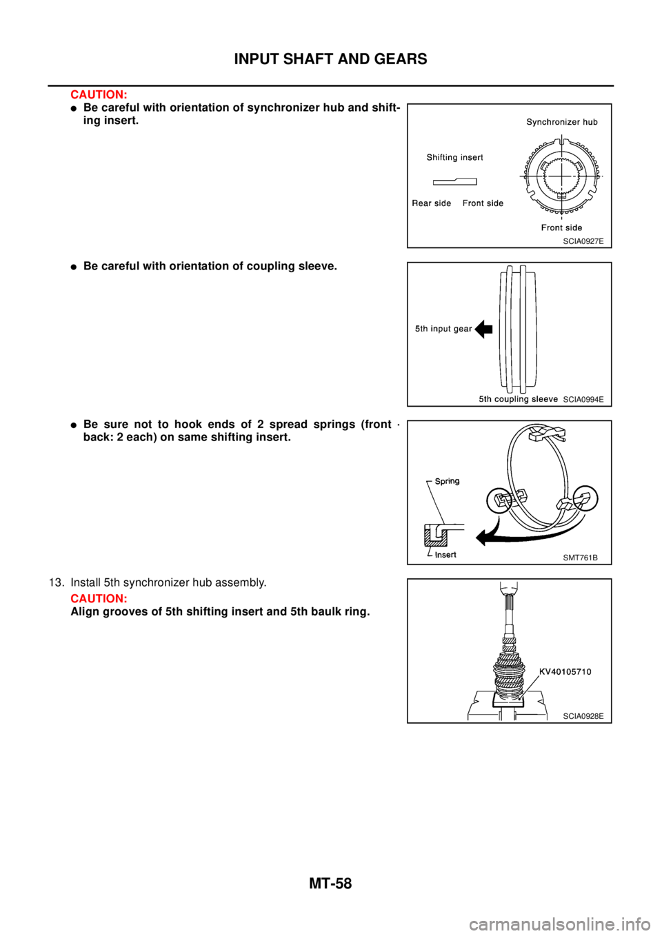
CAUTION:
lBe careful with orientation of synchronizer hub and shift-
ing insert.
lBe careful with orientation of coupling sleeve.
lBe sure not to hook ends of 2 spread springs (front ·
back: 2 each) on same shifting insert.
13. Install 5th synchronizer hub assembly.
CAUTION:
Align grooves of 5th shifting insert and 5th baulk ring.
SCIA0927E
SCIA0994E
SMT761B
SCIA0928E
Page 2595 of 3066
INPUT SHAFT AND GEARS
MT-59
D
E
F
G
H
I
J
K
L
MA
B
MT
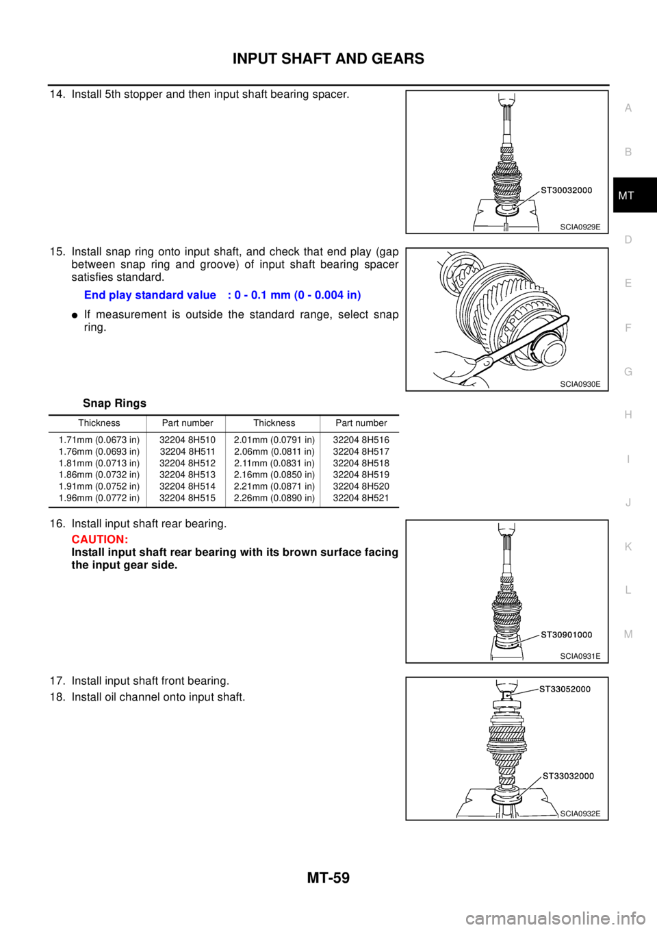
14. Install 5th stopper and then input shaft bearing spacer.
15. Install snap ring onto input shaft, and check that end play (gap
between snap ring and groove) of input shaft bearing spacer
satisfies standard.
lIf measurement is outside the standard range, select snap
ring.
Snap Rings
16. Install input shaft rear bearing.
CAUTION:
Install input shaft rear bearing with its brown surface facing
the input gear side.
17. Install input shaft front bearing.
18. Install oil channel onto input shaft.
SCIA0929E
Endplaystandardvalue :0-0.1mm(0-0.004in)
SCIA0930E
Thickness Part number Thickness Part number
1.71mm (0.0673 in)
1.76mm (0.0693 in)
1.81mm (0.0713 in)
1.86mm (0.0732 in)
1.91mm (0.0752 in)
1.96mm (0.0772 in)32204 8H510
32204 8H511
32204 8H512
32204 8H513
32204 8H514
32204 8H5152.01mm (0.0791 in)
2.06mm (0.0811 in)
2.11mm (0.0831 in)
2.16mm (0.0850 in)
2.21mm (0.0871 in)
2.26mm (0.0890 in)32204 8H516
32204 8H517
32204 8H518
32204 8H519
32204 8H520
32204 8H521
SCIA0931E
SCIA0932E
Page 2596 of 3066
MT-60
INPUT SHAFT AND GEARS
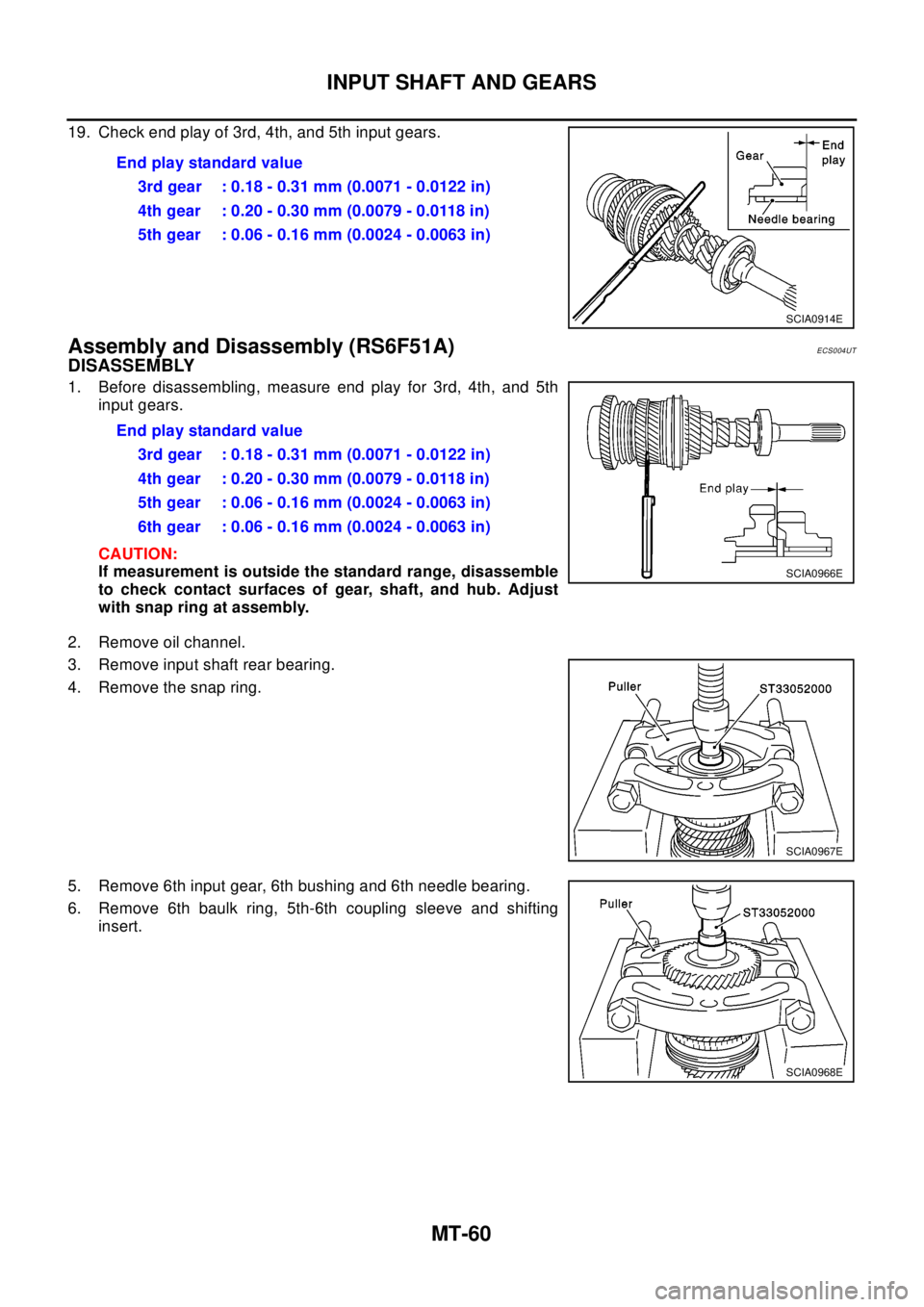
19. Check end play of 3rd, 4th, and 5th input gears.
Assembly and Disassembly (RS6F51A)ECS004UT
DISASSEMBLY
1. Before disassembling, measure end play for 3rd, 4th, and 5th
input gears.
CAUTION:
If measurement is outside the standard range, disassemble
to check contact surfaces of gear, shaft, and hub. Adjust
with snap ring at assembly.
2. Remove oil channel.
3. Remove input shaft rear bearing.
4. Remove the snap ring.
5. Remove 6th input gear, 6th bushing and 6th needle bearing.
6. Remove 6th baulk ring, 5th-6th coupling sleeve and shifting
insert.Endplaystandardvalue
3rd gear : 0.18 - 0.31 mm (0.0071 - 0.0122 in)
4th gear : 0.20 - 0.30 mm (0.0079 - 0.0118 in)
5th gear : 0.06 - 0.16 mm (0.0024 - 0.0063 in)
SCIA0914E
Endplaystandardvalue
3rd gear : 0.18 - 0.31 mm (0.0071 - 0.0122 in)
4th gear : 0.20 - 0.30 mm (0.0079 - 0.0118 in)
5th gear : 0.06 - 0.16 mm (0.0024 - 0.0063 in)
6th gear : 0.06 - 0.16 mm (0.0024 - 0.0063 in)
SCIA0966E
SCIA0967E
SCIA0968E
Page 2597 of 3066
INPUT SHAFT AND GEARS
MT-61
D
E
F
G
H
I
J
K
L
MA
B
MT
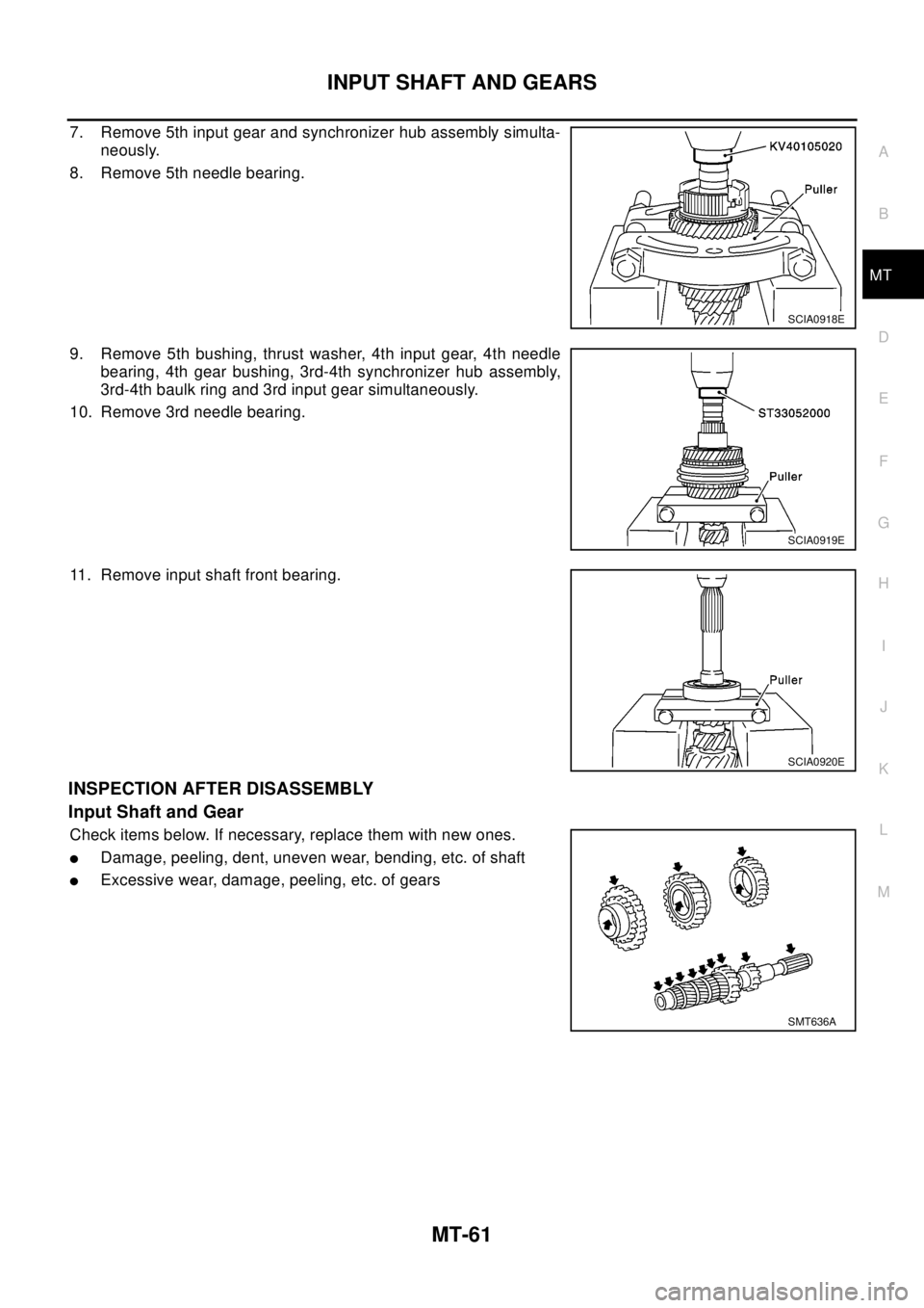
7. Remove 5th input gear and synchronizer hub assembly simulta-
neously.
8. Remove 5th needle bearing.
9. Remove 5th bushing, thrust washer, 4th input gear, 4th needle
bearing, 4th gear bushing, 3rd-4th synchronizer hub assembly,
3rd-4th baulk ring and 3rd input gear simultaneously.
10. Remove 3rd needle bearing.
11. Remove input shaft front bearing.
INSPECTION AFTER DISASSEMBLY
Input Shaft and Gear
Check items below. If necessary, replace them with new ones.
lDamage, peeling, dent, uneven wear, bending, etc. of shaft
lExcessive wear, damage, peeling, etc. of gears
SCIA0918E
SCIA0919E
SCIA0920E
SMT636A
Page 2598 of 3066
MT-62
INPUT SHAFT AND GEARS
Synchronizer
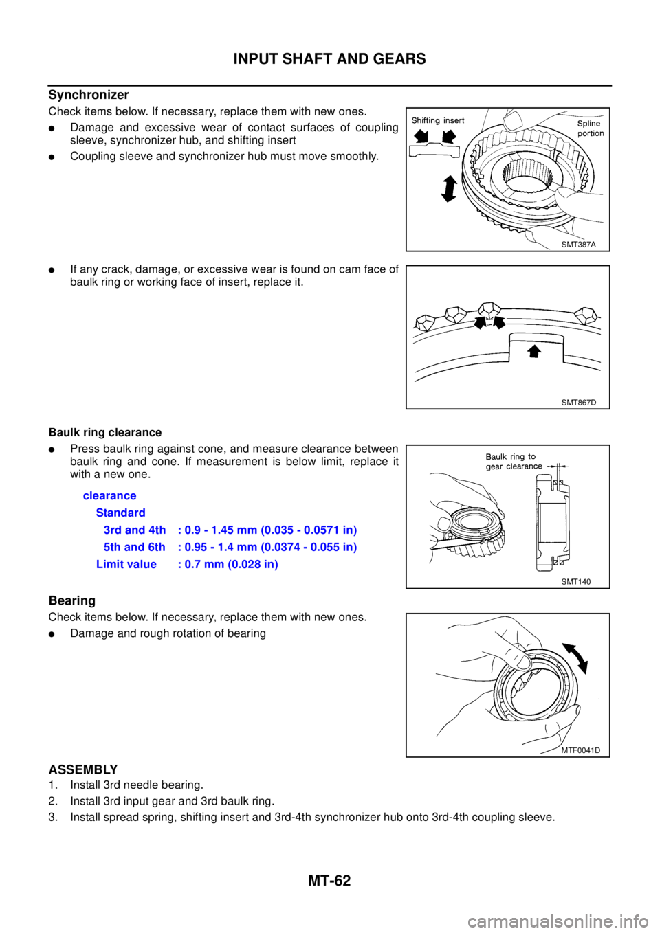
Check items below. If necessary, replace them with new ones.
lDamage and excessive wear of contact surfaces of coupling
sleeve, synchronizer hub, and shifting insert
lCoupling sleeve and synchronizer hub must move smoothly.
lIf any crack, damage, or excessive wear is found on cam face of
baulk ring or working face of insert, replace it.
Baulk ring clearance
lPress baulk ring against cone, and measure clearance between
baulk ring and cone. If measurement is below limit, replace it
with a new one.
Bearing
Check items below. If necessary, replace them with new ones.
lDamage and rough rotation of bearing
ASSEMBLY
1. Install 3rd needle bearing.
2. Install 3rd input gear and 3rd baulk ring.
3. Install spread spring, shifting insert and 3rd-4th synchronizer hub onto 3rd-4th coupling sleeve.
SMT387A
SMT867D
clearance
Standard
3rd and 4th : 0.9 - 1.45 mm (0.035 - 0.0571 in)
5th and 6th : 0.95 - 1.4 mm (0.0374 - 0.055 in)
Limit value : 0.7 mm (0.028 in)
SMT140
MTF0041D
Page 2599 of 3066
INPUT SHAFT AND GEARS
MT-63
D
E
F
G
H
I
J
K
L
MA
B
MT
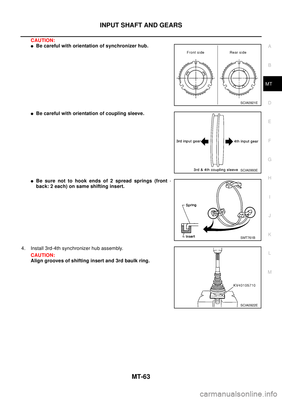
CAUTION:
lBe careful with orientation of synchronizer hub.
lBe careful with orientation of coupling sleeve.
lBe sure not to hook ends of 2 spread springs (front ·
back: 2 each) on same shifting insert.
4. Install 3rd-4th synchronizer hub assembly.
CAUTION:
Align grooves of shifting insert and 3rd baulk ring.
SCIA0921E
SCIA0993E
SMT761B
SCIA0922E
Page 2600 of 3066
MT-64
INPUT SHAFT AND GEARS
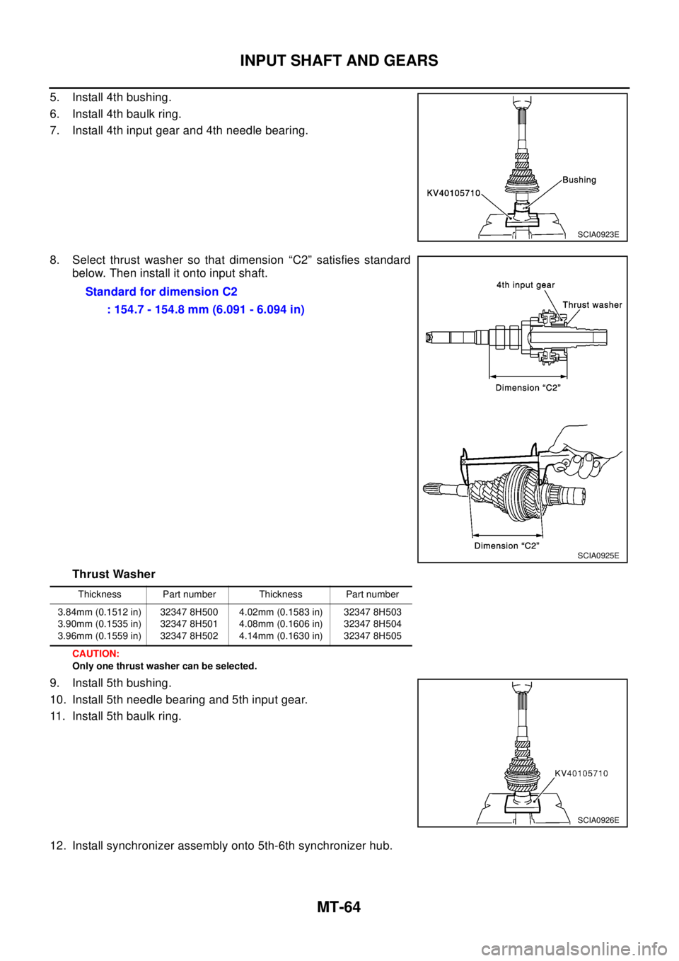
5. Install 4th bushing.
6. Install 4th baulk ring.
7. Install 4th input gear and 4th needle bearing.
8. Select thrust washer so that dimension “C2” satisfies standard
below. Then install it onto input shaft.
Thrust Washer
CAUTION:
Only one thrust washer can be selected.
9. Install 5th bushing.
10. Install 5th needle bearing and 5th input gear.
11. Install 5th baulk ring.
12. Install synchronizer assembly onto 5th-6th synchronizer hub.
SCIA0923E
Standard for dimension C2
: 154.7 - 154.8 mm (6.091 - 6.094 in)
SCIA0925E
Thickness Part number Thickness Part number
3.84mm (0.1512 in)
3.90mm (0.1535 in)
3.96mm (0.1559 in)32347 8H500
32347 8H501
32347 8H5024.02mm (0.1583 in)
4.08mm (0.1606 in)
4.14mm (0.1630 in)32347 8H503
32347 8H504
32347 8H505
SCIA0926E