NISSAN X-TRAIL 2003 Electronic Repair Manual
Manufacturer: NISSAN, Model Year: 2003, Model line: X-TRAIL, Model: NISSAN X-TRAIL 2003Pages: 3066, PDF Size: 51.47 MB
Page 2621 of 3066
REVERSE IDLER SHAFT AND GEARS
MT-85
D
E
F
G
H
I
J
K
L
MA
B
MT
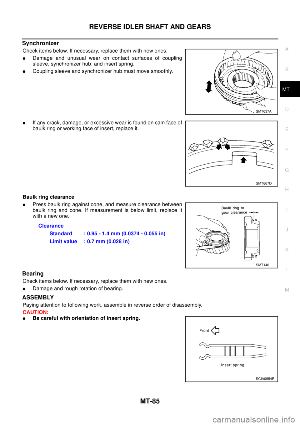
Synchronizer
Check items below. If necessary, replace them with new ones.
lDamage and unusual wear on contact surfaces of coupling
sleeve, synchronizer hub, and insert spring.
lCoupling sleeve and synchronizer hub must move smoothly.
lIf any crack, damage, or excessive wear is found on cam face of
baulk ring or working face of insert, replace it.
Baulk ring clearance
lPress baulk ring against cone, and measure clearance between
baulk ring and cone. If measurement is below limit, replace it
with a new one.
Bearing
Check items below. If necessary, replace them with new ones.
lDamage and rough rotation of bearing.
ASSEMBLY
Paying attention to following work, assemble in reverse order of disassembly.
CAUTION:
lBe careful with orientation of insert spring.
SMT637A
SMT867D
Clearance
Standard : 0.95 - 1.4 mm (0.0374 - 0.055 in)
Limit value : 0.7 mm (0.028 in)
SMT140
SCIA0954E
Page 2622 of 3066
MT-86
FINAL DRIVE
FINAL DRIVE
PFP:38411
Assembly and Disassembly (RS5F51A)ECS004UR
PRE-INSPECTION
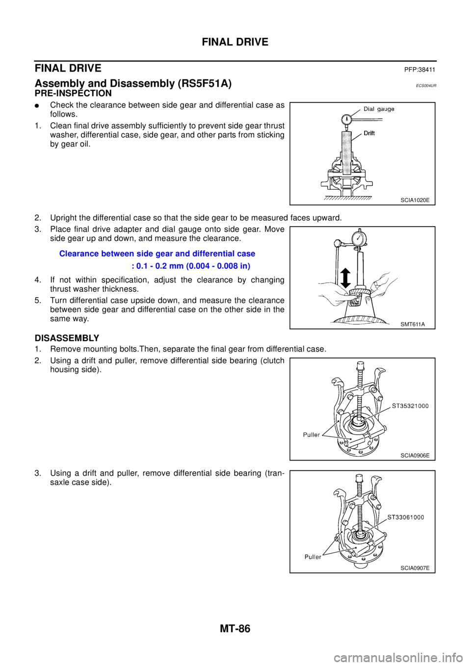
lCheck the clearance between side gear and differential case as
follows.
1. Clean final drive assembly sufficiently to prevent side gear thrust
washer, differential case, side gear, and other parts from sticking
by gear oil.
2. Upright the differential case so that the side gear to be measured faces upward.
3. Place final drive adapter and dial gauge onto side gear. Move
side gear up and down, and measure the clearance.
4. If not within specification, adjust the clearance by changing
thrust washer thickness.
5. Turn differential case upside down, and measure the clearance
between side gear and differential case on the other side in the
same way.
DISASSEMBLY
1. Remove mounting bolts.Then, separate the final gear from differential case.
2. Using a drift and puller, remove differential side bearing (clutch
housing side).
3. Using a drift and puller, remove differential side bearing (tran-
saxle case side).
SCIA1020E
Clearance between side gear and differential case
: 0.1 - 0.2 mm (0.004 - 0.008 in)
SMT611A
SCIA0906E
SCIA0907E
Page 2623 of 3066
FINAL DRIVE
MT-87
D
E
F
G
H
I
J
K
L
MA
B
MT
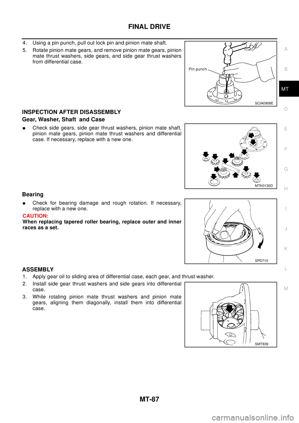
4. Using a pin punch, pull out lock pin and pinion mate shaft.
5. Rotate pinion mate gears, and remove pinion mate gears, pinion
mate thrust washers, side gears, and side gear thrust washers
from differential case.
INSPECTION AFTER DISASSEMBLY
Gear, Washer, Shaft and Case
lCheck side gears, side gear thrust washers, pinion mate shaft,
pinion mate gears, pinion mate thrust washers and differential
case. If necessary, replace with a new one.
Bearing
lCheck for bearing damage and rough rotation. If necessary,
replace with a new one.
CAUTION:
When replacing tapered roller bearing, replace outer and inner
races as a set.
ASSEMBLY
1. Apply gear oil to sliding area of differential case, each gear, and thrust washer.
2. Install side gear thrust washers and side gears into differential
case.
3. While rotating pinion mate thrust washers and pinion mate
gears, aligning them diagonally, install them into differential
case.
SCIA0908E
MTK0135D
SPD715
SMT839
Page 2624 of 3066
MT-88
FINAL DRIVE
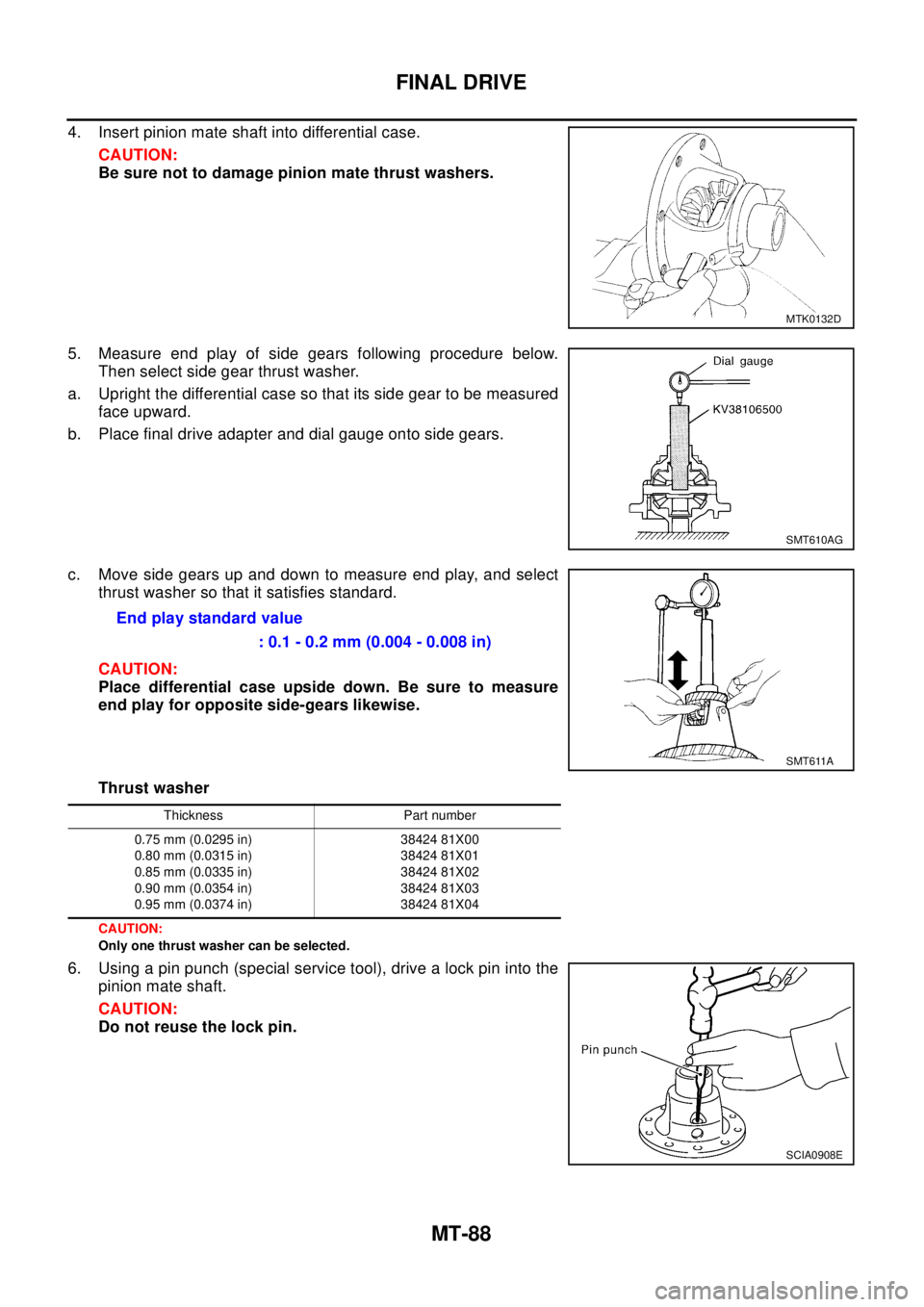
4. Insert pinion mate shaft into differential case.
CAUTION:
Be sure not to damage pinion mate thrust washers.
5. Measure end play of side gears following procedure below.
Then select side gear thrust washer.
a. Upright the differential case so that its side gear to be measured
face upward.
b. Place final drive adapter and dial gauge onto side gears.
c. Move side gears up and down to measure end play, and select
thrust washer so that it satisfies standard.
CAUTION:
Place differential case upside down. Be sure to measure
end play for opposite side-gears likewise.
Thrust washer
CAUTION:
Only one thrust washer can be selected.
6. Using a pin punch (special service tool), drive a lock pin into the
pinion mate shaft.
CAUTION:
Do not reuse the lock pin.
MTK0132D
SMT610AG
Endplaystandardvalue
: 0.1 - 0.2 mm (0.004 - 0.008 in)
SMT611A
Thickness Part number
0.75 mm (0.0295 in)
0.80 mm (0.0315 in)
0.85 mm (0.0335 in)
0.90 mm (0.0354 in)
0.95 mm (0.0374 in)38424 81X00
38424 81X01
38424 81X02
38424 81X03
38424 81X04
SCIA0908E
Page 2625 of 3066
FINAL DRIVE
MT-89
D
E
F
G
H
I
J
K
L
MA
B
MT
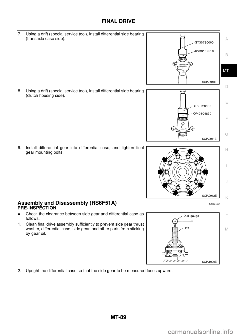
7. Using a drift (special service tool), install differential side bearing
(transaxle case side).
8. Using a drift (special service tool), install differential side bearing
(clutch housing side).
9. Install differential gear into differential case, and tighten final
gear mounting bolts.
Assembly and Disassembly (RS6F51A)ECS004UW
PRE-INSPECTION
lCheck the clearance between side gear and differential case as
follows.
1. Clean final drive assembly sufficiently to prevent side gear thrust
washer, differential case, side gear, and other parts from sticking
by gear oil.
2. Upright the differential case so that the side gear to be measured faces upward.
SCIA0910E
SCIA0911E
SCIA0912E
SCIA1020E
Page 2626 of 3066
MT-90
FINAL DRIVE
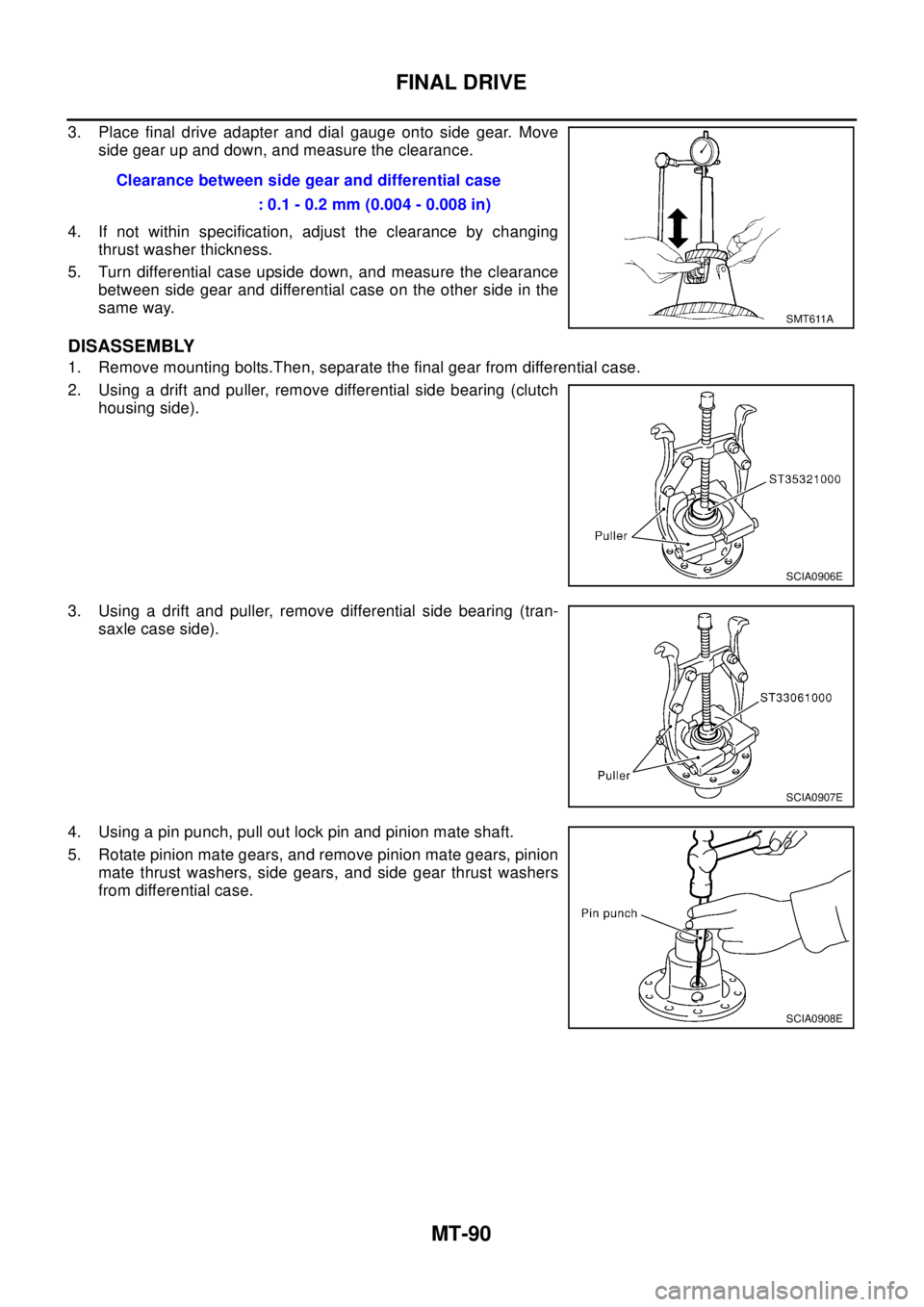
3. Place final drive adapter and dial gauge onto side gear. Move
side gear up and down, and measure the clearance.
4. If not within specification, adjust the clearance by changing
thrust washer thickness.
5. Turn differential case upside down, and measure the clearance
between side gear and differential case on the other side in the
same way.
DISASSEMBLY
1. Remove mounting bolts.Then, separate the final gear from differential case.
2. Using a drift and puller, remove differential side bearing (clutch
housing side).
3. Using a drift and puller, remove differential side bearing (tran-
saxle case side).
4. Using a pin punch, pull out lock pin and pinion mate shaft.
5. Rotate pinion mate gears, and remove pinion mate gears, pinion
mate thrust washers, side gears, and side gear thrust washers
from differential case.Clearance between side gear and differential case
: 0.1 - 0.2 mm (0.004 - 0.008 in)
SMT611A
SCIA0906E
SCIA0907E
SCIA0908E
Page 2627 of 3066
FINAL DRIVE
MT-91
D
E
F
G
H
I
J
K
L
MA
B
MT
INSPECTION AFTER DISASSEMBLY
Gear, Washer, Shaft and Case
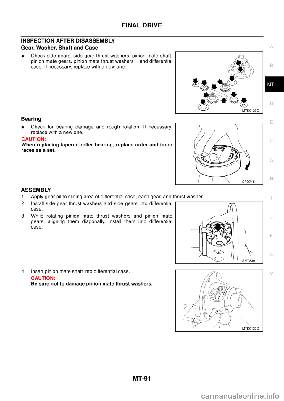
lCheck side gears, side gear thrust washers, pinion mate shaft,
pinion mate gears, pinion mate thrust washers and differential
case. If necessary, replace with a new one.
Bearing
lCheck for bearing damage and rough rotation. If necessary,
replace with a new one.
CAUTION:
When replacing tapered roller bearing, replace outer and inner
races as a set.
ASSEMBLY
1. Apply gear oil to sliding area of differential case, each gear, and thrust washer.
2. Install side gear thrust washers and side gears into differential
case.
3. While rotating pinion mate thrust washers and pinion mate
gears, aligning them diagonally, install them into differential
case.
4. Insert pinion mate shaft into differential case.
CAUTION:
Be sure not to damage pinion mate thrust washers.
MTK0135D
SPD715
SMT839
MTK0132D
Page 2628 of 3066
MT-92
FINAL DRIVE
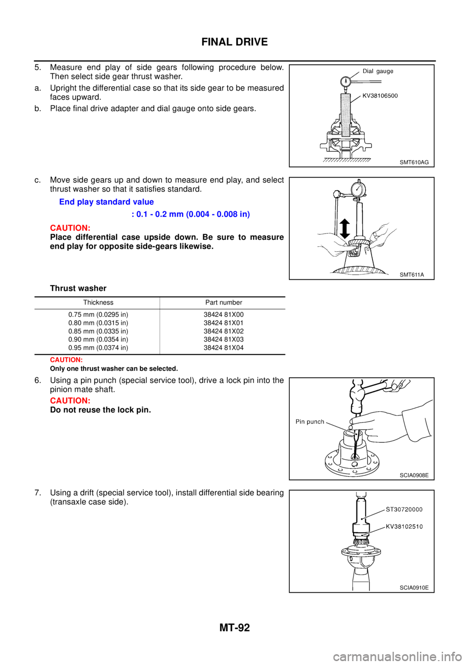
5. Measure end play of side gears following procedure below.
Then select side gear thrust washer.
a. Upright the differential case so that its side gear to be measured
faces upward.
b. Place final drive adapter and dial gauge onto side gears.
c. Move side gears up and down to measure end play, and select
thrust washer so that it satisfies standard.
CAUTION:
Place differential case upside down. Be sure to measure
end play for opposite side-gears likewise.
Thrust washer
CAUTION:
Only one thrust washer can be selected.
6. Using a pin punch (special service tool), drive a lock pin into the
pinion mate shaft.
CAUTION:
Do not reuse the lock pin.
7. Using a drift (special service tool), install differential side bearing
(transaxle case side).
SMT610AG
Endplaystandardvalue
: 0.1 - 0.2 mm (0.004 - 0.008 in)
SMT611A
Thickness Part number
0.75 mm (0.0295 in)
0.80 mm (0.0315 in)
0.85 mm (0.0335 in)
0.90 mm (0.0354 in)
0.95 mm (0.0374 in)38424 81X00
38424 81X01
38424 81X02
38424 81X03
38424 81X04
SCIA0908E
SCIA0910E
Page 2629 of 3066
FINAL DRIVE
MT-93
D
E
F
G
H
I
J
K
L
MA
B
MT
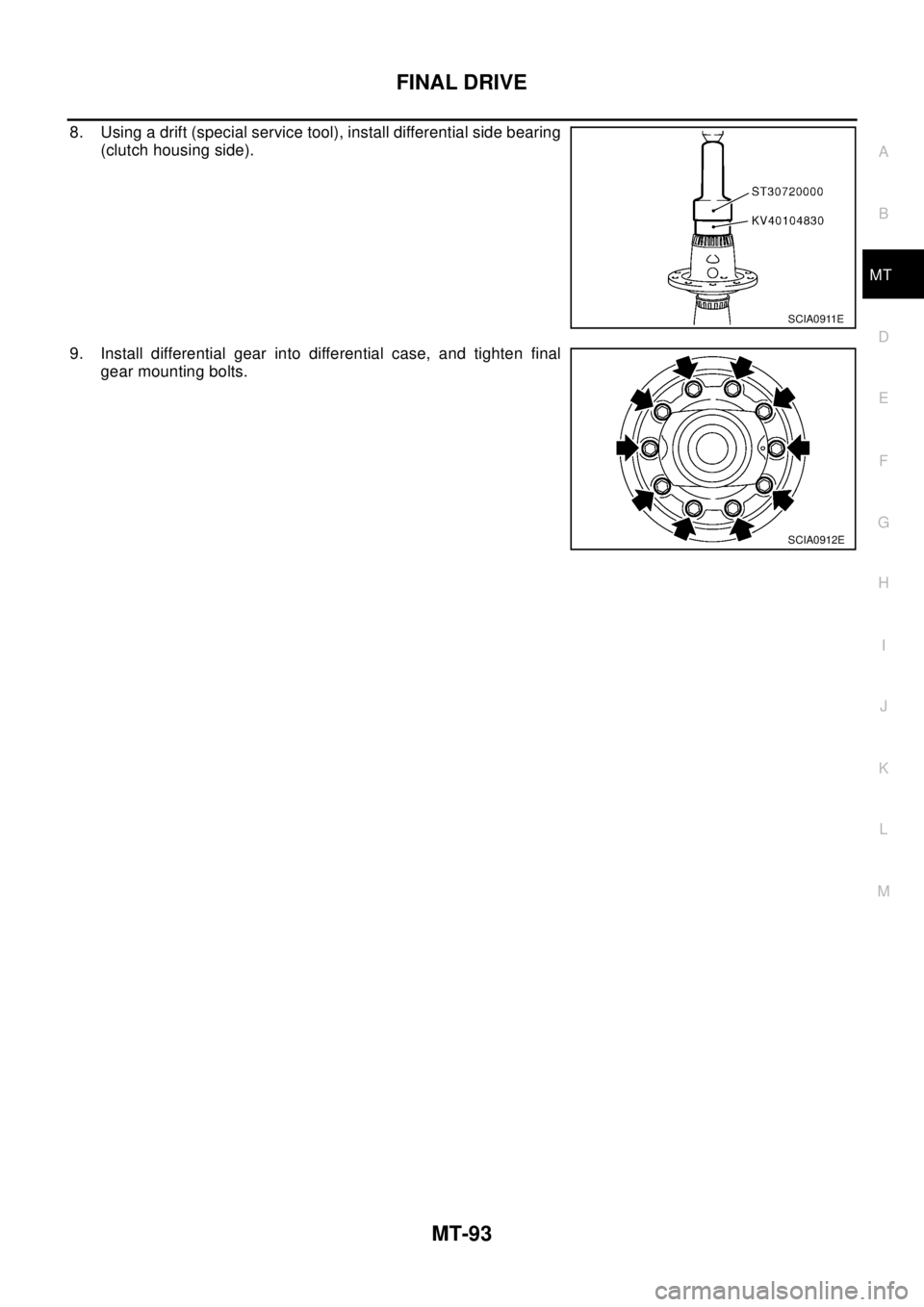
8. Using a drift (special service tool), install differential side bearing
(clutch housing side).
9. Install differential gear into differential case, and tighten final
gear mounting bolts.
SCIA0911E
SCIA0912E
Page 2630 of 3066
MT-94
SHIFT CONTROL
SHIFT CONTROL
PFP:32982
Inspection (RS5F51A)ECS004US
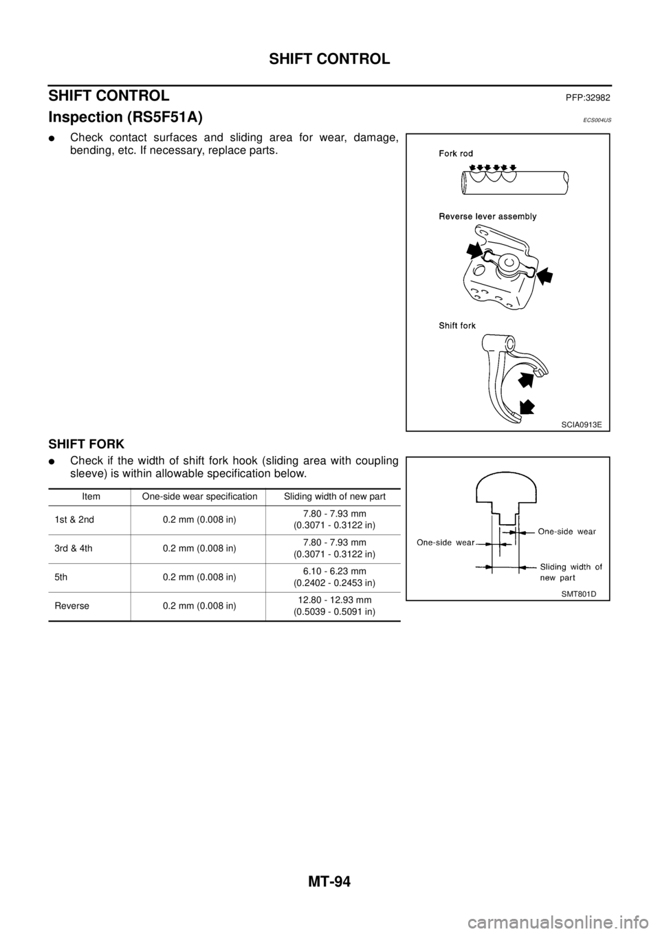
lCheck contact surfaces and sliding area for wear, damage,
bending, etc. If necessary, replace parts.
SHIFT FORK
lCheck if the width of shift fork hook (sliding area with coupling
sleeve) is within allowable specification below.
SCIA0913E
Item One-side wear specification Sliding width of new part
1st & 2nd 0.2 mm (0.008 in)7.80 - 7.93 mm
(0.3071 - 0.3122 in)
3rd & 4th 0.2 mm (0.008 in)7.80 - 7.93 mm
(0.3071 - 0.3122 in)
5th 0.2 mm (0.008 in)6.10 - 6.23 mm
(0.2402 - 0.2453 in)
Reverse 0.2 mm (0.008 in)12.80 - 12.93 mm
(0.5039 - 0.5091 in)
SMT801D