8C–8ENTERTAINMENT
Front Speaker
Removal
1. Disconnect the battery ground cable.
2. Pull the grille(1) to release the locks and then remove
it.
3. Remove four screws and disconnect the
connector(3) to remove the speaker(2).
890RW013
Installation
To install, follow the removal steps in the reverse order.
ENTERTAINMENT8C–9
Rear Speaker
Removal
1. Disconnect the battery ground cable.
2. Pull the grille(1) to release the locks and then remove
it.
3. Remove four screws and disconnect the
connector(3) to remove the speaker(2).
890RW015
Installation
To install, follow the removal steps in the reverse order.
The chassis electrical system is a 12–volt system with a
negative ground polarity.
Wire size are appropriate to respective circuits, and
classified by color. (The classification of harnesses by
color is shown on the circuit diagram for ease of harness
identification.)
The wire size is determined by load capacity and the
length of wire required.
The vehicle harnesses are: body harness, chassis
harness, engine room harness, instrument harness,
transmission harness, engine ECGI harness, dome light
harness, door harness, rear body harness, tailgate
harness, SRS harness and battery cables.
The harnesses are protected either by tape or corrugated
tube, depending on harness location.
The circuit for each system consists of the power source,
wire, fuse, relay, switch, load parts and ground, all of
which are shown on the circuit diagram.
In this section, each electrical device is classified by
system.
For major parts shown on the circuit based on the circuit
diagram for each system, a summary, diagnosis of
troubles and inspection procedures are detailed.
Notes for Working on Electrical
Items
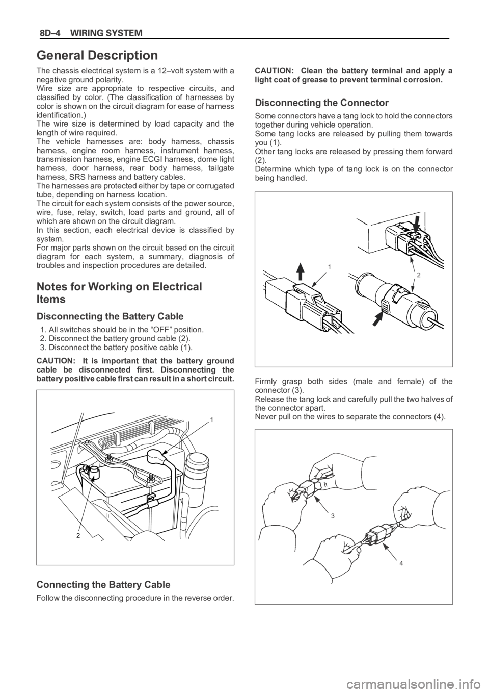
Disconnecting the Battery Cable
1. All switches should be in the “OFF” position.
2. Disconnect the battery ground cable (2).
3. Disconnect the battery positive cable (1).
CAUTION: It is important that the battery ground
cable be disconnected first. Disconnecting the
battery positive cable first can result in a short circuit.
Connecting the Battery Cable
Follow the disconnecting procedure in the reverse order.CAUTION: Clean the battery terminal and apply a
light coat of grease to prevent terminal corrosion.
Disconnecting the Connector
Some connectors have a tang lock to hold the connectors
together during vehicle operation.
Some tang locks are released by pulling them towards
you (1).
Other tang locks are released by pressing them forward
(2).
Determine which type of tang lock is on the connector
being handled.
Firmly grasp both sides (male and female) of the
connector (3).
Release the tang lock and carefully pull the two halves of
the connector apart.
Never pull on the wires to separate the connectors (4).
2
1
General Description
1
2
3
4
When removing the connector for relay (MR5B type) (5),
unfasten the tang lock of the connector by using a
screwdriver, then pull the relay out as shown in the figure.
Connecting the Connector
Firmly grasp both sides (male and female) of the
connectors. Be sure that both sides of the connectors are
aligned with each other.
Firmly but carefully push the two sides of the connectors
together until a distinct click is heard (2).
Do not connect them by force if they can not be connected
smoothly (1).
Connector Inspection
Use a circuit tester to check the connector for continuity.
Insert the test probes (1) from the connector wire side.
Never insert the circuit tester test probes (2) into the
connector open end to test the continuity.
Broken or open connector terminals will result.
5
1
2
1
2
Waterproof Connector Inspection
It is not possible to insert the test probes (2) into the
connector wire side of a waterproof connector.
Use one side of a connector (1) with its wires cut to make
the test. Connect the test connector to the connector to
be tested (3). Connect the test probes to the cut wires to
check the connector continuity.
Connector Pin Removal – Connector
Housing Tang Lock Type
1. Insert a slender shaft (1) into the connector housing
open end (5).
2. Push the tang lock (2) up (in the direction of the arrow
in the illustration).
Pull the wire (3) with pin (4) free from the wire side of
the connector.
Connector Pin Removal – Pin Tang Lock
Ty p e
1. Insert a slender shaft (1) into the connector housing
open end (5).
2. Push the tang lock (2) flat (toward the wire (3) side of
the connector.
Pull the wire with pin (4) free from the wire side of the
connector.
Connector Pin Insertion
1. Check that the tang lock (1) is fully up.
2. Insert the pin (3) from the connector wire (2) side.
Push the pin in until the tang lock closes firmly.
3. Gently pull on the wires to make sure that the
connector pin is firmly set in place.
1
3
21
2
3
5
4
1
2
3
4 51
2
3
Parts Handling
Be careful when handling electrical parts. They should not
be dropped or thrown, because short circuit or other
damage may result.
Cable Harness
1. When installing the parts, be careful not to pinch or
wedge the wiring harness.
2. All electrical connections must be kept clean and tight.3. Use a grommet or guard tube (1) to protect the wiring
harness from contacting a sharp edge or surface (2).
4. Position the wiring harness with enough clearance
from the other parts and guard the wiring harness with
a vinyl tube (2) and clips (1) to avoid direct contact.
12
2
1


