OPEL FRONTERA 1998 Workshop Manual
Manufacturer: OPEL, Model Year: 1998, Model line: FRONTERA, Model: OPEL FRONTERA 1998Pages: 6000, PDF Size: 97 MB
Page 5461 of 6000

6E–32
4JX1–TC ENGINE DRIVEABILITY AND EMISSIONS
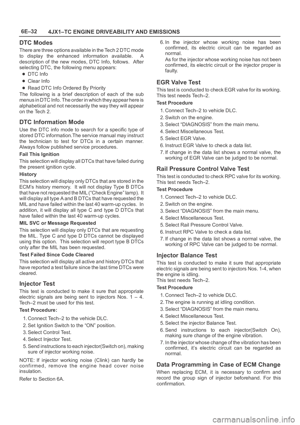
DTC Modes
There are three options available in the Tech 2 DTC mode
to display the enhanced information available. A
description of the new modes, DTC Info, follows. After
selecting DTC, the following menu appears:
DTC Info
Clear Info
Read DTC Info Ordered By Priority
The following is a brief description of each of the sub
menus in DTC Info. The order in which they appear here is
alphabetical and not necessarily the way they will appear
on the Tech 2.
DTC Information Mode
Use the DTC info mode to search for a specific type of
stored DTC information.The service manual may instruct
the technician to test for DTCs in a certain manner.
Always follow published service procedures.
Fail This Ignition
This selection will display all DTCs that have failed during
the present ignition cycle.
History
This selection will display only D T C s t h a t a r e s t o r e d i n t h e
ECM’s history memory. It will not display Type B DTCs
that have not requested the MIL (“Check Engine” lamp). It
will display all type A and B DTCs that have requested the
MIL and have failed within the last 40 warm-up cycles. In
addition, it will display all type C and type D DTCs that
have failed within the last 40 warm-up cycles.
MIL SVC or Message Requested
This selection will display only DTCs that are requesting
the MIL. Type C and type D DTCs cannot be displayed
using this option. This selection will report type B DTCs
only after the MIL has been requested.
Test Failed Since Code Cleared
This selection will display all active and history DTCs that
have reported a test failure since the last time DTCs were
cleared.
Injector Test
This test is conducted to make it sure that appropriate
electric signals are being sent to injectors Nos. 1 – 4.
Tech–2 must be used for this test.
Test Procedure:
1. Connect Tech–2 to the vehicle DLC.
2. Set Ignition Switch to the “ON” position.
3. Select Control Test.
4. Select Injector Test.
5. Send instructions to each injector(Switch on), making
sure of injector working noise.
NOTE: If injector working noise (Clink) can hardly be
confirmed, remove the engine head cover noise
insulation.
Refer to Section 6A.6. In the injector whose working noise has been
confirmed, its electric circuit can be regarded as
normal.
As for the injector whose working noise has not been
confirmed, its electric circuit or the injector proper is
faulty.
EGR Valve Test
This test is conducted to check EGR valve for its working.
This test needs Tech–2.
Test Procedure
1. Connect Tech–2 to vehicle DLC.
2. Switch on the engine.
3. Select “DIAGNOSIS” from the main menu.
4. Select Miscellaneous Test.
5. Select EGR Valve.
6. Instruct EGR Valve to check a data list.
7. If change in the data list shows a normal valve, the
working of EGR Valve can be judged to be normal.
Rail Pressure Control Valve Test
This test is conducted to check RPC valve for its working.
This test needs Tech–2.
Test Procedure
1. Connect Tech–2 to vehicle DLC.
2. Switch on the engine.
3. Select “DIAGNOSIS” from the main menu.
4. Select Miscellaneous Test.
5. Select Rail Pressure Control Valve.
6. Instruct RPC Valve to check a data list.
7. If change in the data list shows a normal valve, the
working of RPC Valve can be judged to be normal.
Injector Balance Test
This test is conducted to make it sure that appropriate
electric signals are being sent to injectors Nos. 1-4, when
the engine is idling.
This test needs Tech–2.
Test Procedure
1. Connect Tech–2 to vehicle DLC.
2. The engine is running at idling condition.
3. Select “DIAGNOSIS” from the main menu.
4. Select Miscellaneous Test.
5. Select the injector Balance Test.
6. Send instructions to each injector(Switch On),
making sure change of the engine vibration.
7. In the injector whose change of the vibration has been
confirmed, it’s electric circuit can be regarded as
normal.
Data Programming in Case of ECM Change
When replacing ECM, it is necessary to confirm and
record the group sign of injector beforehand. For this
confirmation.
Page 5462 of 6000

6E–33 4JX1–TC ENGINE DRIVEABILITY AND EMISSIONS
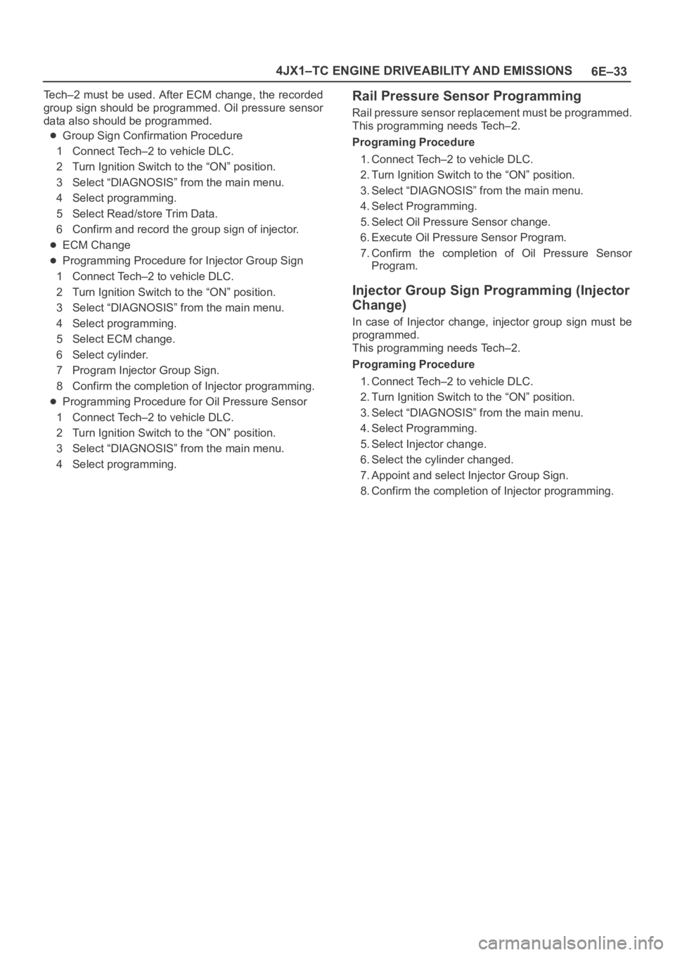
Tech–2 must be used. After ECM change, the recorded
group sign should be programmed. Oil pressure sensor
data also should be programmed.
Group Sign Confirmation Procedure
1 Connect Tech–2 to vehicle DLC.
2 Turn Ignition Switch to the “ON” position.
3 Select “DIAGNOSIS” from the main menu.
4 Select programming.
5 Select Read/store Trim Data.
6 Confirm and record the group sign of injector.
ECM Change
Programming Procedure for Injector Group Sign
1 Connect Tech–2 to vehicle DLC.
2 Turn Ignition Switch to the “ON” position.
3 Select “DIAGNOSIS” from the main menu.
4 Select programming.
5 Select ECM change.
6 Select cylinder.
7 Program Injector Group Sign.
8 Confirm the completion of Injector programming.
Programming Procedure for Oil Pressure Sensor
1 Connect Tech–2 to vehicle DLC.
2 Turn Ignition Switch to the “ON” position.
3 Select “DIAGNOSIS” from the main menu.
4 Select programming.
Rail Pressure Sensor Programming
Rail pressure sensor replacement must be programmed.
This programming needs Tech–2.
Programing Procedure
1. Connect Tech–2 to vehicle DLC.
2. Turn Ignition Switch to the “ON” position.
3. Select “DIAGNOSIS” from the main menu.
4. Select Programming.
5. Select Oil Pressure Sensor change.
6. Execute Oil Pressure Sensor Program.
7. Confirm the completion of Oil Pressure Sensor
Program.
Injector Group Sign Programming (Injector
Change)
In case of Injector change, injector group sign must be
programmed.
This programming needs Tech–2.
Programing Procedure
1. Connect Tech–2 to vehicle DLC.
2. Turn Ignition Switch to the “ON” position.
3. Select “DIAGNOSIS” from the main menu.
4. Select Programming.
5. Select Injector change.
6. Select the cylinder changed.
7. Appoint and select Injector Group Sign.
8. Confirm the completion of Injector programming.
Page 5463 of 6000

6E–34
4JX1–TC ENGINE DRIVEABILITY AND EMISSIONS
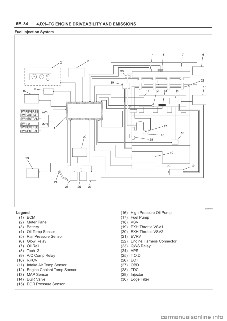
Fuel Injection System
060RW178
Legend
(1) ECM
(2) Meter Panel
(3) Battery
(4) Oil Temp Sensor
(5) Rail Pressure Sensor
(6) Glow Relay
(7) Oil Rail
(8) Tech–2
(9) A/C Comp Relay
(10) RPCV
(11) Intake Air Temp Sensor
(12) Engine Coolant Temp Sensor
(13) MAP Sensor
(14) EGR Valve
(15) EGR Pressure Sensor(16) High Pressure Oil Pump
(17) Fuel Pump
(18) VSV
(19) EXH Throttle VSV1
(20) EXH Throttle VSV2
(21) EVRV
(22) Engine Harness Connector
(23) QWS Relay
(24) APS
(25) T.O.D
(26) ECT
(27) OBD
(28) TDC
(29) Injector
(30) Edge Filter
Page 5464 of 6000

6E–35 4JX1–TC ENGINE DRIVEABILITY AND EMISSIONS
Guid to the System
Fuel Injection system is an HEUI (Hydraulically
Actuated, Electronically Controlled, Unit, Injector)
type. In this type of injector system, the oil
pressurized by means of High Pressure Oil Pump
(16) is fed through Rail Pressure Control Valve (10)
and Oil Rail (7) to Injector (29) from which fuel is
injected under this oil pressure.
For diagnosis, therefore, the Rail Pressure as well as
the Electric Circuit must be inspected.
On-Board Diagnostic (OBD) System Check
A Group
060RW135
Page 5465 of 6000

6E–36
4JX1–TC ENGINE DRIVEABILITY AND EMISSIONS
B Group
060RW133
C Group
060RW129
Page 5466 of 6000

6E–37 4JX1–TC ENGINE DRIVEABILITY AND EMISSIONS
D Group
060RW134
Circuit Description
The on-board diagnostic system check is the starting
point for any driveability complaint diagnosis. Before
using this procedure, perform a careful visual/physical
check of the ECM and engine grounds for cleanliness and
tightness.
The on-board diagnostic system check is an organized
approach to identifying a problem created by an
electronic engine control system malfunction.
Diagnostic Aids
An intermittent may be caused by a poor connection,
rubbed-through wire insulation or a wire broken inside the
insulation. Check for poor connections or a damaged
harness. Inspect the ECM harness and connector for
improper mating, broken locks, improperly formed or
damaged terminals, poor terminal-to-wire connection,
and damaged harness.
Test Description
Number(s) below refer to the step number(s) on the
Diagnostic Chart:
1. The MIL (“Check Engine” lamp) should be “ON”
steady with the ignition “ON”/engine “OFF.” If not,
Chart A-1 should be used to isolate the malfunction.
2. Checks the Class 2 data circuit and ensures that the
ECM is able to transmit serial data.
3. This test ensures that the ECM is capable of
controlling the MIL (“Check Engine” lamp) and the
MIL (“Check Engine” lamp) driver circuit is not
shorted to ground.
4. If the engine will not start, the
Cranks But Will Not
Run
chart should be used to diagnose the condition.
7. A Tech 2 parameter which is not within the typical
range may help to isolate the area which is causing
the problem.
9. When the ECM is replaced, the characteristic data of
injector and rail pressure sensor should be inputted.
Page 5467 of 6000

6E–38
4JX1–TC ENGINE DRIVEABILITY AND EMISSIONS
On- Board Diagnostic (OBD) System Check
StepActionVa l u e ( s )Ye sNo
11. Ignition “ON,” engine “OFF.”
2. Observe the malfunction indicator lamp (MIL or
“Check Engine” lamp).
Is the MIL (“Check Engine” lamp)“ON?”
—Go to Step 2
Go to No MIL
(“Check
Engine” lamp)
21. Ignition “OFF.”
2. Install a Tech 2.
3. Ignition “ON.”
4. Attempt to display ECM engine data with the Tech 2.
Does the Tech 2 display ECM data?
—Go to Step 3Go to Step 8
31. Using the Tech 2 output tests function, select MIL
(“Check Engine” lamp) dash lamp control and
command the MIL (“Check Engine” lamp) “OFF.”
2. Observe the MIL (“Check Engine” lamp).
Did the MIL (“Check Engine” lamp) turn “OFF?”
—Go to Step 4
Go to MIL
(“Check
Engine” lamp)
On Steady
4Attempt to start the engine.
Did the engine start and continue to run?
—Go to Step 5
Go to Cranks
But Will Not
Run
5Select “Display DTCs” with the Tech 2.
Are any DTCs stored?
—Go to Step 6Go to Step 7
6Are two or more of the following DTCs stored?
A Group; P0337, P0342, P1193, P1404, P1405,
P1488
B Group; P0337, P0342
C Group; P0112, P0117, P0182, P0197
D Group; P0107, P0405, P1194, P1485
—
Go to Chart,
“Multiple
ECM
Information
Sensor DTCs
Set”
Go to
applicable
DTC table
7Compare ECM data values displayed on the Tech 2 to
the typical engine scan data values.
Are the displayed values normal or close to the typical
values?
—Go to Step 8
Refer to
indicated
Component
System
Checks
81. Ignition “OFF,” disconnect the ECM.
2. Ignition “ON,” engine “OFF.”
3. Check the Class 2 data circuit for an open, short to
ground, or short to voltage. Also, check the DLC
ignition feed circuit for an open or short to ground
and the DLC ground circuit for an open.
4. If a problem is found, repair as necessary.
Was a problem found?
—Go to Step 2Go to Step 9
9Check the Tech 2 on other vehicle.
Was Tech 2 abnormal?
—Go to Step 11Go to Step 10
10Replace the ECM (Refer to the Data Programming in
Case of ECM change).
Is the action complete?
—Go to Step 2—
11Repair the Tech 2 or prepare another Tech 2.
Is the action complete?
—Go to Step 2—
Page 5468 of 6000

6E–39 4JX1–TC ENGINE DRIVEABILITY AND EMISSIONS
Engine Control Module ECM
Diagnosis
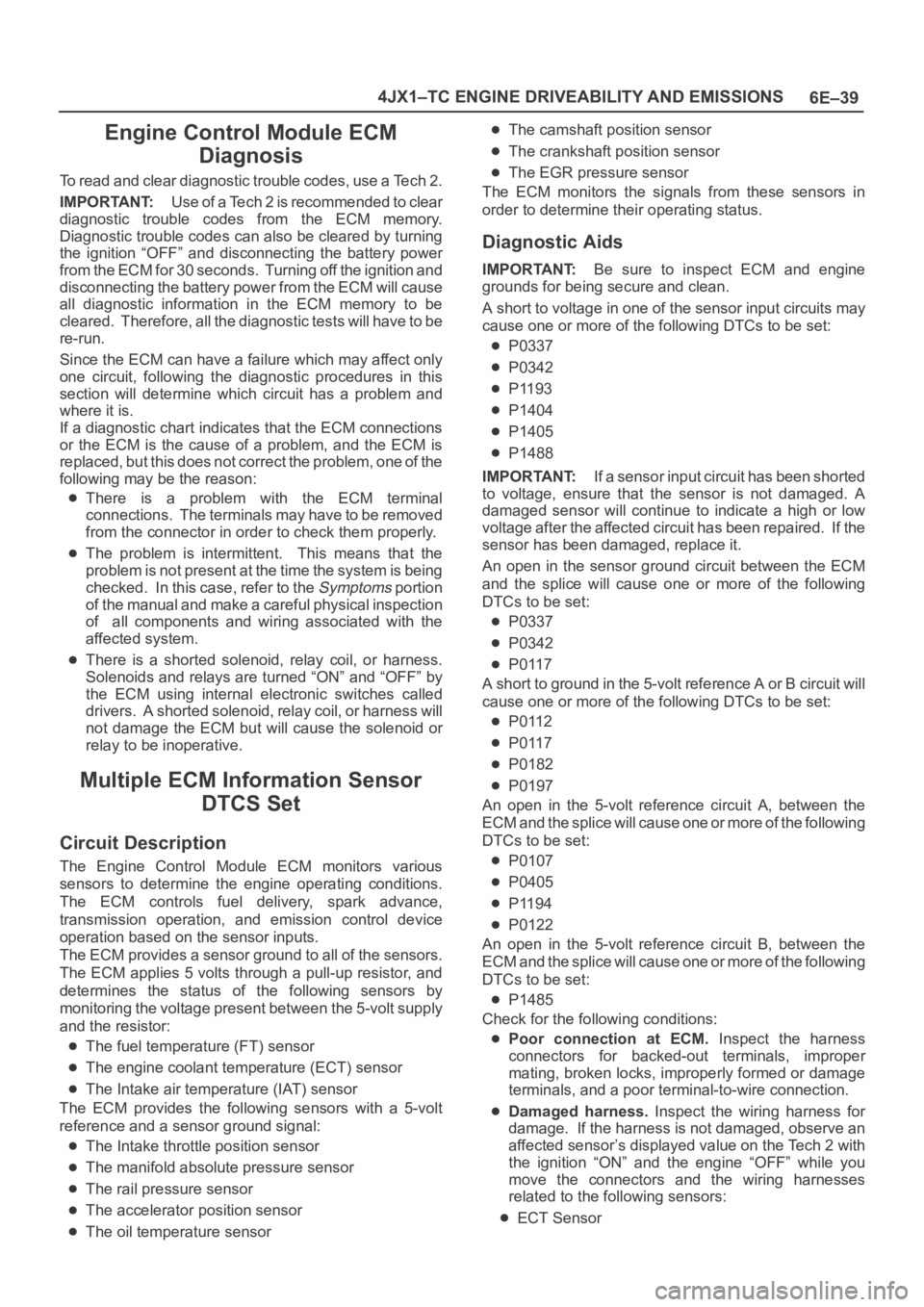
To read and clear diagnostic trouble codes, use a Tech 2.
IMPORTANT:Use of a Tech 2 is recommended to clear
diagnostic trouble codes from the ECM memory.
Diagnostic trouble codes can also be cleared by turning
the ignition “OFF” and disconnecting the battery power
from the ECM for 30 seconds. Turning off the ignition and
disconnecting the battery power from the ECM will cause
all diagnostic information in the ECM memory to be
cleared. Therefore, all the diagnostic tests will have to be
re-run.
Since the ECM can have a failure which may affect only
one circuit, following the diagnostic procedures in this
section will determine which circuit has a problem and
where it is.
If a diagnostic chart indicates that the ECM connections
or the ECM is the cause of a problem, and the ECM is
replaced, but this does not correct the problem, one of the
following may be the reason:
There is a problem with the ECM terminal
connections. The terminals may have to be removed
from the connector in order to check them properly.
The problem is intermittent. This means that the
problem is not present at the time the system is being
checked. In this case, refer to the
Symptoms portion
of the manual and make a careful physical inspection
of all components and wiring associated with the
affected system.
There is a shorted solenoid, relay coil, or harness.
Solenoids and relays are turned “ON” and “OFF” by
the ECM using internal electronic switches called
drivers. A shorted solenoid, relay coil, or harness will
not damage the ECM but will cause the solenoid or
relay to be inoperative.
Multiple ECM Information Sensor
DTCS Set
Circuit Description
The Engine Control Module ECM monitors various
sensors to determine the engine operating conditions.
The ECM controls fuel delivery, spark advance,
transmission operation, and emission control device
operation based on the sensor inputs.
The ECM provides a sensor ground to all of the sensors.
The ECM applies 5 volts through a pull-up resistor, and
determines the status of the following sensors by
monitoring the voltage present between the 5-volt supply
and the resistor:
The fuel temperature (FT) sensor
The engine coolant temperature (ECT) sensor
The Intake air temperature (IAT) sensor
The ECM provides the following sensors with a 5-volt
reference and a sensor ground signal:
The Intake throttle position sensor
The manifold absolute pressure sensor
The rail pressure sensor
The accelerator position sensor
The oil temperature sensor
The camshaft position sensor
The crankshaft position sensor
The EGR pressure sensor
The ECM monitors the signals from these sensors in
order to determine their operating status.
Diagnostic Aids
IMPORTANT:Be sure to inspect ECM and engine
grounds for being secure and clean.
A short to voltage in one of the sensor input circuits may
cause one or more of the following DTCs to be set:
P0337
P0342
P1193
P1404
P1405
P1488
IMPORTANT:If a sensor input circuit has been shorted
to voltage, ensure that the sensor is not damaged. A
damaged sensor will continue to indicate a high or low
voltage after the affected circuit has been repaired. If the
sensor has been damaged, replace it.
An open in the sensor ground circuit between the ECM
and the splice will cause one or more of the following
DTCs to be set:
P0337
P0342
P0117
A short to ground in the 5-volt reference A or B circuit will
cause one or more of the following DTCs to be set:
P0112
P0117
P0182
P0197
An open in the 5-volt reference circuit A, between the
ECM and the splice will cause one or more of the following
DTCs to be set:
P0107
P0405
P1194
P0122
An open in the 5-volt reference circuit B, between the
ECM and the splice will cause one or more of the following
DTCs to be set:
P1485
Check for the following conditions:
Poor connection at ECM. Inspect the harness
connectors for backed-out terminals, improper
mating, broken locks, improperly formed or damage
terminals, and a poor terminal-to-wire connection.
Damaged harness. Inspect the wiring harness for
damage. If the harness is not damaged, observe an
affected sensor’s displayed value on the Tech 2 with
the ignition “ON” and the engine “OFF” while you
move the connectors and the wiring harnesses
related to the following sensors:
ECT Sensor
Page 5469 of 6000

6E–40
4JX1–TC ENGINE DRIVEABILITY AND EMISSIONS
MAP Sensor
CMP Sensor
CKP Sensor
EGR Pressure Sensor
EGR VSV
RPCV
IAT Sensor
Intake Throttle Motor
Fuel Temperature Sensor
Oil Temperature Sensor
Rail Pressure Sensor
Multiple ECM Information Sensor DTCs Set
StepActionVa l u e ( s )Ye sNo
1Was the “On-Board Diagnostic (OBD) System Check”
performed?
—Go to Step 2
Go to OBD
System
Check
21. Turn the ignition “OFF,” disconnect the ECM.
2. Turn the ignition “ON,” check the 5 volt reference D
circuit for the following conditions:
D poor connection at the ECM.
An open between the ECM connector and the
splice.
D short to ground.
D short to voltage.
Is there an open or short?
—Go to Step 3Go to Step 4
3Repair the open or short.
Is the action complete?
—Verify repair—
4Check the sensor ground circuit for the following
conditions:
A poor connection at the ECM or the affected
sensors.
An open between the ECM connector and the
affected sensors.
Is there an open or a poor connection?
—Go to Step 5Go to Step 6
5Repair the open or the poor connection.
Is the action complete?
—Verify repairGo to Step 6
6Replace the ECM (Refer to the Data Programming in
Case of ECM change).
Is the action complete?
—
Go to OBD
System
Check
—
Page 5470 of 6000

6E–41 4JX1–TC ENGINE DRIVEABILITY AND EMISSIONS
EGR (Exhaust Gas Recirculation)
Diagnosis
A diagnosis of the EGR system is covered by DTC
P1403.
EGR VSV circuit diagnosis is covered by DTC P1404.
EGR pressure sensor diagnosis is covered by DTC
P405 and/or P406.
EGR EVRV circuit diagnosis is covered by DTC
P1405. Refer to the DTC charts.
Tech 2 Data Definitions and Ranges
A/C CLUTCH–Tech 2 Displays ON or OFF–
Indicates whether the A/C has commanded the A/C
clutch ON.
MAP kPa — Tech 2 Range 10-105 kPa/0.00-5.00
Vo l t s —
The manifold absolute pressure reading is determined
from the MAP sensor signal monitored during key up and
wide open throttle (WOT) conditions. The manifold
absolute pressure is used to compensate for altitude
differences and is normally displayed around “61-104”
depending on altitude and manifold absolute pressure.
CMP ACT. COUNTER –Cam Position
DESIRED IDLE — Tech 2 Range 0-3187 RPM —
The idle speed that the ECM is commanding. The ECM
will compensate for various engine loads based on engine
coolant temperature, to keep the engine at the desired
speed.
ECT — (Engine Coolant Temperature) Tech 2
Range –40
C to 151C (–40F to 304F) —
The engine coolant temperature (ECT) is mounted in the
coolant stream and sends engine temperature
information to the ECM. The ECM applies 5 volts to the
ECT sensor circuit. The sensor is a thermistor which
changes internal resistance as temperature changes.
When the sensor is cold (high resistance), the ECM
monitors a high signal voltage and interprets that as a cold
engine. As the sensor warms (decreasing resistance),
the voltage signal will decrease and the ECM will interpret
the lower voltage as a warm engine.
ENGINE RUN TIME — Tech 2 Range
00:00:00-99:99:99 Hrs:Min:Sec —
Indicates the time elapsed since the engine was started.
If the engine is stopped, engine run time will be reset to
00:00:00.
ENGINE SPEED — Range 0-9999 RPM —
Engine speed is computed by the ECM from the 57X
reference input. It should remain close to desired idle
under various engine loads with engine idling.Air Intake Valve meter POSITION — Tech 2 Range
0-100 % —
IAT (INTAKE AIR TEMPERATURE)— Tech 2 Range
–40
C to 151C (–40F to 304F) —
The ECM converts the resistance of the intake air
temperature sensor to degrees. Intake air temperature
(IAT) is used by the ECM to adjust fuel delivery and spark
timing according to incoming air density.
MAP — Tech 2 Range 10-105 kPa (0.00-4.97 Volts)—
The manifold absolute pressure (MAP) sensor measures
the change in the boost pressure.
MIL — Tech 2 Displays ON or OFF —
Indicates the ECM commanded state of the malfunction
indicator lamp.
AP — Tech 2 Range 0%-100% —
AP (Accelerator position) angle is computed by the ECM
from the AP sensor voltage. AP angle should display
“0%” at idle and “100%” at wide open throttle.
AP SENSOR — Tech 2 Range 0.00-5.00 Volts —
The voltage being monitored by the ECM on the AP
sensor signal circuit.
VEHICLE SPEED—Tech 2 Range 0-255 km/h (0-155
mph)–
The vehicle speed sensor signal is converted into km/h
and mph for display.
Typical Scan Data Values
Use the Typical Scan Data Values Table only after the
On-Board Diagnostic System Check has been
completed, no DTC(s) were noted, and you have
determined that the on-board diagnostics are functioning
properly. Tech 2 values from a properly-running engine
may be used for comparison with the engine you are
diagnosing. The typical scan data values represent
values that would be seen on a normally-running engine.
NOTE: A Tech 2 that displays faulty data should not be
used, and the problem should be reported to the Tech 2
manufacturer. Use of a faulty Tech 2 can result in
misdiagnosis and unnecessary replacement of parts.
Only the parameters listed below are referred to in this
service manual for use in diagnosis. For further
information on using the Tech 2 to diagnose the ECM and
related sensors, refer to the applicable reference section
listed below. If all values are within the typical range
described below, refer to the
Symptoms section for
diagnosis.
Test Conditions
Engine running, lower radiator hose hot, transmission in
park or neutral, accessaries off, brake not applied and air
conditioning off.