check engine OPEL FRONTERA 1998 Workshop Manual
[x] Cancel search | Manufacturer: OPEL, Model Year: 1998, Model line: FRONTERA, Model: OPEL FRONTERA 1998Pages: 6000, PDF Size: 97 MB
Page 2523 of 6000

7C–14CLUTCH
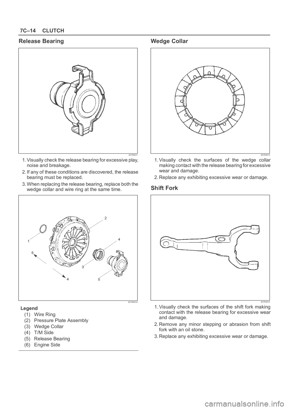
Release Bearing
201RS011
1. Visually check the release bearing for excessive play,
noise and breakage.
2. If any of these conditions are discovered, the release
bearing must be replaced.
3. When replacing the release bearing, replace both the
wedge collar and wire ring at the same time.
201RW010
Legend
(1) Wire Ring
(2) Pressure Plate Assembly
(3) Wedge Collar
(4) T/M Side
(5) Release Bearing
(6) Engine Side
Wedge Collar
201RS013
1. Visually check the surfaces of the wedge collar
making contact with the release bearing for excessive
wear and damage.
2. Replace any exhibiting excessive wear or damage.
Shift Fork
201RS014
1. Visually check the surfaces of the shift fork making
contact with the release bearing for excessive wear
and damage.
2. Remove any minor stepping or abrasion from shift
fork with an oil stone.
3. Replace any exhibiting excessive wear or damage.
Page 2529 of 6000

7C–20CLUTCH
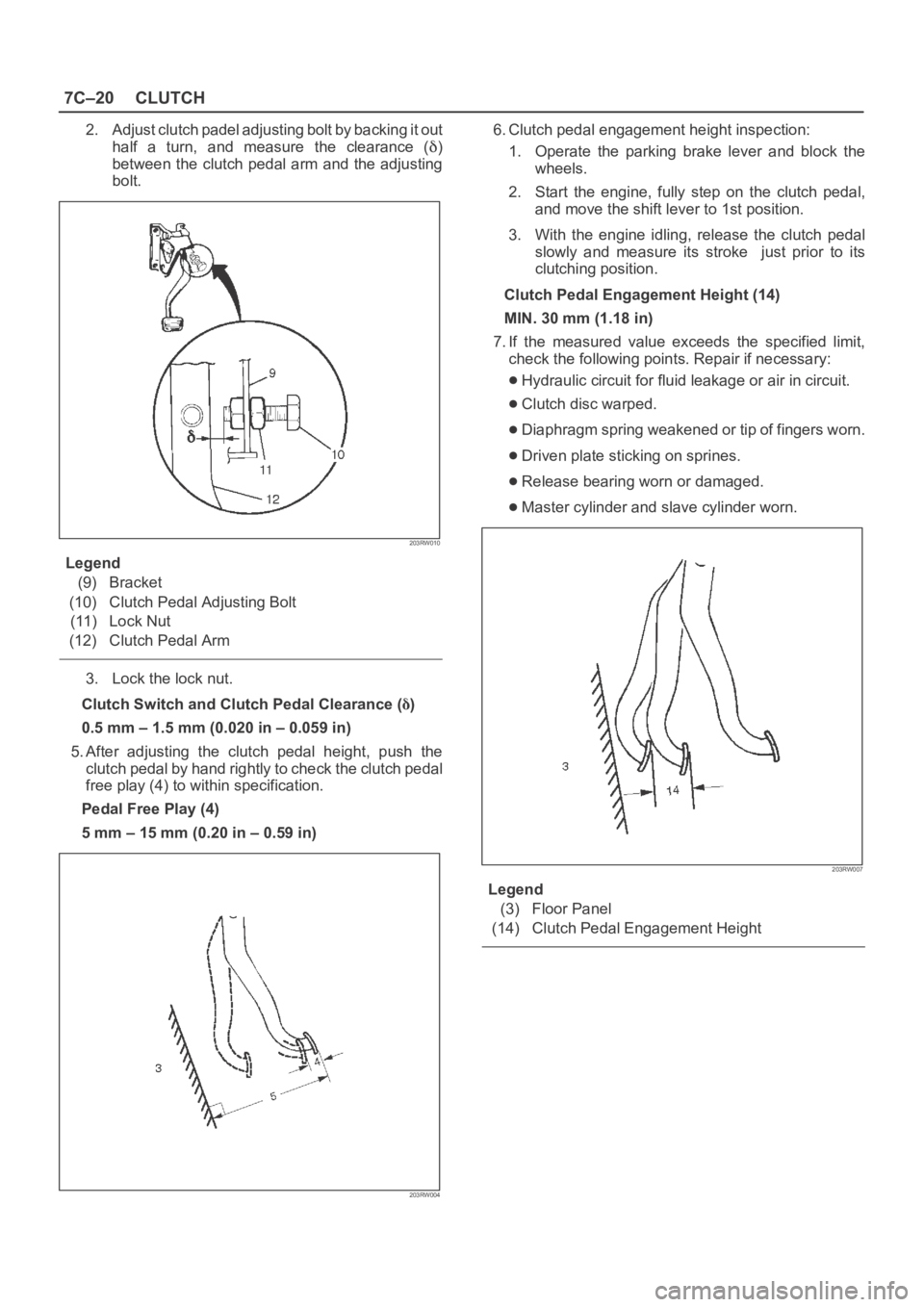
2. Adjust clutch padel adjusting bolt by backing it out
half a turn, and measure the clearance (
)
between the clutch pedal arm and the adjusting
bolt.
203RW010
Legend
(9) Bracket
(10) Clutch Pedal Adjusting Bolt
(11) Lock Nut
(12) Clutch Pedal Arm
3. Lock the lock nut.
Clutch Switch and Clutch Pedal Clearance (
)
0.5 mm – 1.5 mm (0.020 in – 0.059 in)
5. After adjusting the clutch pedal height, push the
clutch pedal by hand rightly to check the clutch pedal
free play (4) to within specification.
Pedal Free Play (4)
5 mm – 15 mm (0.20 in – 0.59 in)
203RW004
6. Clutch pedal engagement height inspection:
1. Operate the parking brake lever and block the
wheels.
2. Start the engine, fully step on the clutch pedal,
and move the shift lever to 1st position.
3. With the engine idling, release the clutch pedal
slowly and measure its stroke just prior to its
clutching position.
Clutch Pedal Engagement Height (14)
MIN. 30 mm (1.18 in)
7. If the measured value exceeds the specified limit,
check the following points. Repair if necessary:
Hydraulic circuit for fluid leakage or air in circuit.
Clutch disc warped.
Diaphragm spring weakened or tip of fingers worn.
Driven plate sticking on sprines.
Release bearing worn or damaged.
Master cylinder and slave cylinder worn.
203RW007
Legend
(3) Floor Panel
(14) Clutch Pedal Engagement Height
Page 2568 of 6000

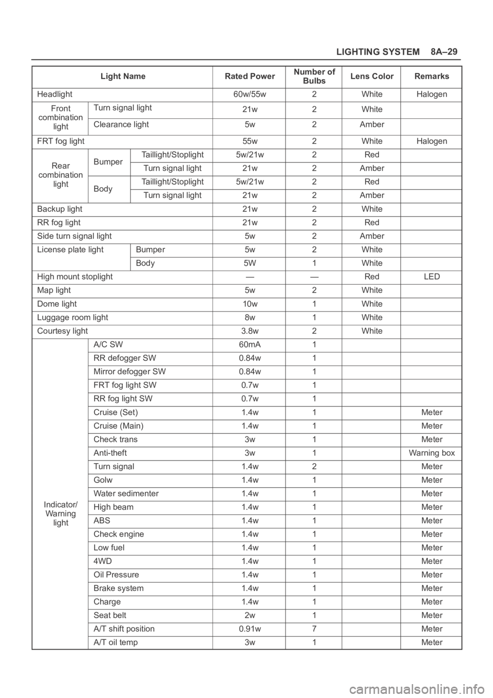
LIGHTING SYSTEM8A–29
Light NameRated PowerNumber of
BulbsLens ColorRemarks
Headlight60w/55w2WhiteHalogen
FrontTurn signal light21w2Whitecombination
lightClearance light5w2Amber
FRT fog light55w2WhiteHalogen
Taillight/Stoplight5w/21w2Red
RearBumperTurn signal light21w2Ambercombination
lightTaillight/Stoplight5w/21w2RedBodyTurn signal light21w2Amber
Backup light21w2White
RR fog light21w2Red
Side turn signal light5w2Amber
License plate lightBumper5w2White
Body5W1White
High mount stoplight——RedLED
Map light5w2White
Dome light10w1White
Luggage room light8w1White
Courtesy light3.8w2White
A/C SW60mA1
RR defogger SW0.84w1
Mirror defogger SW0.84w1
FRT fog light SW0.7w1
RR fog light SW0.7w1
Cruise (Set)1.4w1Meter
Cruise (Main)1.4w1Meter
Check trans3w1Meter
Anti-theft3w1Warning box
Turn signal1.4w2Meter
Golw1.4w1Meter
Water sedimenter1.4w1Meter
Indicator/High beam1.4w1MeterWa rnin g
lightABS1.4w1Meter
Check engine1.4w1Meter
Low fuel1.4w1Meter
4WD1.4w1Meter
Oil Pressure1.4w1Meter
Brake system1.4w1Meter
Charge1.4w1Meter
Seat belt2w1Meter
A/T shift position0.91w7Meter
A/T oil temp3w1Meter
Page 2601 of 6000

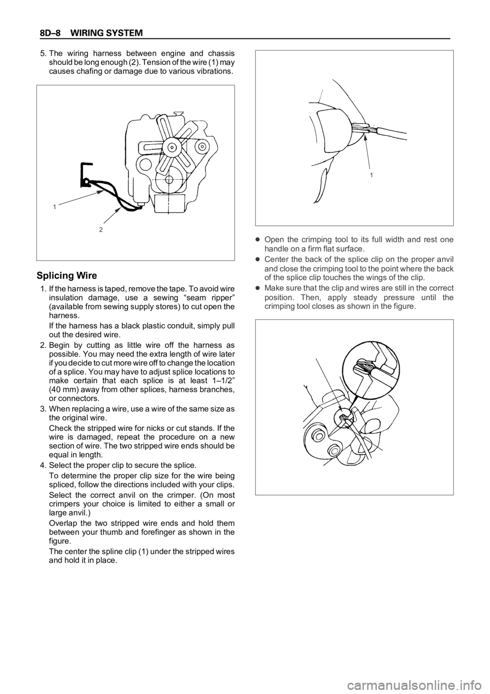
5. The wiring harness between engine and chassis
should be long enough (2). Tension of the wire (1) may
causes chafing or damage due to various vibrations.
Splicing Wire
1. If the harness is taped, remove the tape. To avoid wire
insulation damage, use a sewing “seam ripper”
(available from sewing supply stores) to cut open the
harness.
If the harness has a black plastic conduit, simply pull
out the desired wire.
2. Begin by cutting as little wire off the harness as
possible. You may need the extra length of wire later
if you decide to cut more wire off to change the location
of a splice. You may have to adjust splice locations to
make certain that each splice is at least 1–1/2”
(40 mm) away from other splices, harness branches,
or connectors.
3 . W h e n r e p l a c i n g a w i r e , u s e a w i r e o f t h e s a m e s i z e a s
the original wire.
Check the stripped wire for nicks or cut stands. If the
wire is damaged, repeat the procedure on a new
section of wire. The two stripped wire ends should be
equal in length.
4. Select the proper clip to secure the splice.
To determine the proper clip size for the wire being
spliced, follow the directions included with your clips.
Select the correct anvil on the crimper. (On most
crimpers your choice is limited to either a small or
large anvil.)
Overlap the two stripped wire ends and hold them
between your thumb and forefinger as shown in the
figure.
The center the spline clip (1) under the stripped wires
and hold it in place.
Open the crimping tool to its full width and rest one
handle on a firm flat surface.
Center the back of the splice clip on the proper anvil
and close the crimping tool to the point where the back
of the splice clip touches the wings of the clip.
Make sure that the clip and wires are still in the correct
position. Then, apply steady pressure until the
crimping tool closes as shown in the figure.
2
11
Page 2992 of 6000

WIRING SYSTEM 8D–399
1. Check to see if the battery voltage is normal.
2. Check to see if the fuse is normal.
3. Replace the anti–theft & keyless entry control unit with one reserved for test. If a trouble recurs even after replacing
the control unit, find out the cause of the trouble by referring to “System check procedure” and the following list.
ITEM MALFUNCTION POSSIBLE CAUSE DETECTING METHOD REMARKS
ANTI–THEFT
indicator light
does not flash
ANTI–THEFT
indicator light
does not turn off.
(Steadily on)
When door is
opened by pulling
up locking knob,
alarm does not
operate
Alarm does not
stop. Indicator light
does not change
to fully ON
condition, or does
not come on at
all.Burnt out indicator
light bulb possible.
Refer to “Connector
check table” in this
system.
Refer to “Connector
check table” in this
system.
Refer to “Connector
check table” in this
system.
Refer to “Connector
check table” in this
system.
Refer to “Connector
check table” in this
system.
Refer to “Connector
check table” in this
system. Defective contact of door switch,
or open circuit in door switch
wiring.
Short circuit in the detect switch.
Engine hood, doors and tailgate
are not fully closed and locked.
Defective door switch, or short
circuit in switch wiring.
Defective tamper switch, or short
circuit in wiring.
Defective lock switch, or short
circuit in wiring.
Defective engine hood switch, or
short circuit in wiring.
Defective tailgate switch, or short
circuit in wiring.
Defective control unit.
Poor contact of lock switch, or
open circuit in wiring.
Broken wire in wiring to headlight
and horn, or a blown fuse.
Defective contact of detect
switch, or damaged switch wiring.With door open, dome light and
courtesy light do not come on.
Check the control unit connector.
Check to see if doors are closed
and locked.
Dome light and courtesy light
remain lit on after closing doors.
Check the control unit connector.
Check the control unit connector.
Check the control unit connector.
Luggage room light remains lit
after closing tailgate.
Check alarm operation (See No.
46 of “System check procedure”),
possible cause is a poor contact
of lock switch of an open circuit in
wiring.
Check to see if headlights go out.
Check the control unit connector.
Check the control unit connector. A
C
D
E B
Page 2993 of 6000

8D–400 WIRING SYSTEM
ITEM MALFUNCTION POSSIBLE CAUSE DETECTING METHOD REMARKS
Even when door
unlocked with
key, alarm
operates.
Alarm does not
operate even with
tailgate open.
Even when
tailgate is opened
with key, alarm
does not stop.
Even when
engine hood is
opened with
remote release,
alarm does not
operate
Even when
starter switch is
turned, alarm
does not stop
Indicator light
continues
flashingRefer to “Connector
check table” in this
system.
Refer to “Connector
check table” in this
system.
Refer to “Connector
check table” in this
system. Defective contact of detect
switch, or damaged switch wiring.
Door detect switch is assembled
to wrong door.
Defective contact of tailgate
switch, or defective wiring.
Defective contact of tailgate
detect switch, or damage wiring.
Damaged engine hood switch or
wiring.
Defective contact of starter
switch.
Damaged door switch, or a short
circuit in wiring.
Damaged tamper switch, or a
short circuit in wiring.Check the control unit connector.
When key is turned to lock
position, alarm stops.
When luggage room light switch
is turned on with tailgate open,
luggage room light does not
come on.
Check the control unit connector.
With starter switch turned to
“ACC” position, audio, cigarette
lighter and door mirrors (on
“ACC” circuit) do not operate.
After closing door, dome light and
courtesy light remain on.
Check the control unit connector. F
G
H
I
J
K
Page 2994 of 6000

WIRING SYSTEM 8D–401
STEP OPERATION ITEM TO BE CHECKEDITEM OF
REMARKS
MALFUNCTION
Be sure to lock door
with locking knob.
Activate alarm
device.
All doors are
unlocked.
With key set at unlock
position, check to see
if alarm stops.
All doors are
locked.
Activate alarm
device.
Activate alarm
device.
Only left rear door
is unlocked. Check to see if engine hood,
tailgate and doors are closed and
locked.
Check to see if indicator light
remains lit off.
Check to see if indicator light
flashes.
Check to see if dome light and
courtesy light illuminate.
Check to see if indicator light
changes from flashing to steadily
on.
Check to see if indicator light
turns off in about 10 seconds.
Check to see if alarm operates
(with headlight flashing, and horn
blaring intermittently.)
Check to see if alarm stops.
Check to see if indicator light
turns on.
Check to see if indicator light
goes off after about 10 seconds.
Check to see if alarm does not
operate.
Check to see if indicator light
turns on.
Check to see if indicator light
goes off after about 10 seconds.
Check to see if alarm starts. Turn starter key to “ON” position.
Open windows fully.
Pull out starter key after turning it
back to “OFF” position.
Unlock left front door with locking
knob.
Open left front door. (And get out
of the vehicle.)
Close left front door.
Lock left front door.
Wait about 10 seconds
Unlock left front door with locking
knob.
Insert key into key cylinder of left
front door and turn it in unlock
direction.
Lock left front door.
Wait for about 10 seconds.
Unlock left front door with key.
Lock left front door with key.
Wait for about 10 seconds.
Unlock left rear door with locking
knob.K
A
B
C
D
E
B
C
F
B
C
D 1
2
3
4
5
6
7
8
9
10
11
12
13
14
15
16
Page 2997 of 6000

8D–404 WIRING SYSTEM
STEP OPERATION ITEM TO BE CHECKEDITEM OF
REMARKS
MALFUNCTION
Activate alarm
device. Check to see if indicator light
goes off after about 10 seconds.
Check to see if alarm operates.
Check to see if alarm stops. Wait about 10 seconds.
Open engine hood with engine
hood release handle.
Insert key into starter switch and
turn it to “ACC” position.C
I
J 45
46
47
NOTE:When the connector of the anti–theft & keyless entry control unit is disconnected, the starter is inoperative.
In the checking of short wheel base model, Step Nos. 16 through 21 and Step Nos. 31 through 36 are omitted.
Page 2998 of 6000

WIRING SYSTEM 8D–405
TERMINAL
CONNECTIONCHECK
OPERATIONCIRCUIT
NO. ITEM CONDITION
1 FRT door switch–LH, RH ContinuityOpen door Continuity
Close door No continuity
2 RR door switch–LH, RH ContinuityOpen door Continuity
Close door No continuity
3— — – –
4 Door lock key switch–LH, RH Continuity Lock with key Continuity
5 FRT door lock switch–LH, RH Continuity Lock Continuity
6 Tailgate switch ContinuityOpen tailgate Continuity
Close tailgate No continuity
8 Anti–theft horn Voltage – Approx. 12V
10 Battery Voltage – Approx. 12V
11 Door switch ContinuityUnlock with locking knob Continuity
Lock with locking knob No continuity
12 Engine hood switch ContinuityOpen engine hood Continuity
Close engine hood No continuity
13 Detect switch ContinuityUnlock with key Continuity
Lock with key No continuity
14 Door lock key switch Continuity Unlock Continuity
15 FRT door lock switch–LH, RH Continuity Unlock Continuity
16 Tamper switch Continuity – No continuity
17 Ground Continuity – Continuity
18 Starter switch Voltage Starter switch “ACC” Approx. 12V
19 Indicator light Voltage – Approx. 12V
20 Dome light Voltage Dome light “DOOR” position Approx. 12V
21 Anti-theft relay Voltage – Approx. 12V
22 Starter relay VoltageMode switch “P” or “N” Approx. 12V
Clutch pedal depressed Approx. 12V
Check the anti–theft & keyless entry control unit harness side connector B–20 by using a circuit tester.
Page 3186 of 6000

METER AND GAUGE8E–9
Meter Assembly–Gasoline W/O TOD–2
Connector No. I–9
Te r m i n a lFunction
1A/T oil temp warning light
2Seat belt warning light
3Check trans warning light
4Brake warning light
5Check engine warning light
6Charge warning light
7Cigarette lighter illumination light
8Illumination controller
9Tachometer
10D position (A/T)
11—
12A/T shift indicator control unit
13—
142 position (A/T)
15Starter switch
16Cruise set indicator light
17Cruise main indicator light
184WD indicator light
19Ground (Gauge)
20—
21Winter drive indicator light
22Oil pressure warning light
23—
24Air bag warning light
25Power drive indicator light
26—
27—
28Turn signal indicator light (Left)
29—
30Ground
Connector No. I–10
Te r m i n a lFunction
1Turn signal indicator light (Right)
2L position (A/T)
3R position (A/T)
4Engine coolant temperature gauge
5Speedometer
6—
7—
8Battery (+)
9—
10Rear fog light
11P position (A/T)
12N position (A/T)
133 position (A/T)
14High-beam indicator light (–)
15High-beam indicator light (+)
16ABS indicator light
17—
18Fuel warning light
19Oil pressure gauge
20Fuel gauge
21—
22—