OPEL GT-R 1973 Owner's Guide
Manufacturer: OPEL, Model Year: 1973, Model line: GT-R, Model: OPEL GT-R 1973Pages: 625, PDF Size: 17.22 MB
Page 31 of 625
1 B- 101973 OPEL SERVICE #MANUAL
STARTlhG SYSTEM
/
ALL
MODEILS
CONTENTS
Subject
DESCRIPTION AND OPERATION:
Starting SystemDescription
. . . . . . . . . . . . . . . . . . . . . . . . . . . . . . . . . . . . \
. . . . . .
DIAGNOSIS:
Starting System Diagnosis,
. . . . . . . . . . . . . . . . . , . . . . . . . . . . . . . . . . . . \
. . . . . . . .
MAINTENANCE AND ADJUSTMENTS:Starting System
Checks. . . . . . . . . . . . . . . . . . . . . . . . . . . . . . . . . . . . \
. . . . . . . . . . . . . .
MAJOR REPAIR:
Removal. . . . . . . . . . . . . . . . . . . . . . . . . . . . . . . . . . . . \
. . . . . . . . . . . . . . . . . ., . . . . . . . . . . . . . . . . . . . . . . . . . .
Disassembly. . . . . . . . . . . . . . . . . . . . . . . . . . . . . . . a.... . . . . . . . . . . . . . . . . . . . . . . . . . . . . . . . . . . . .\
CleaningandInspecting Parts. . . . . . . . . . . . . . . . . . . . . . . . . . . . . . . . . . . . \
. .
Replacing Field Coils. . . . . . . . . . . , . . . . . . . . . . . . . . . . . . . . . . . . \
. . . . . . . . . . . . . . . . . . . .
Checking and Replacing Brushes. . . . . . . . . . . . . . . . . . . . . . . . . . . . . . . .
Replacing Bushings. . . . . . . . . . . . . . . . . . . . . . . . . . . . . . . , . . . . \
. . . . . . . . . . . . . . . . . . . . . .
Assembly. . . . . . . . . . . . . . . . . . . . . . . . . . . . . . . . . . . . \
. . . . . . . . . . . . . . . . . . . . . . . . . . . . . . . . . . . . \
. . . . . .
Installation. . . . . . . . . . . . . . . . . . . . . . . . . . . . . . . . . . . . \
. . . . . . . . . . . . . . . . . . . . . . . . . . . . . . . . . . . . \
. . . .
SPECIFICATIONS:
Starter Specifications
. . . . , . , . . . . . . . . . . . . . . . . . . . . . . . . . . . . . . . . . . . . . . . . . . . . . . .
Page No.
lB-10
16-10
18-12
18-13
18-13
18-14
18-14
16-15
18-16
lB-16
18-17
18-17
DESCRIPTION AND OPERATION
STARTING SYSTEM DESCRlPTlqN
The new Delco Remy starter for 1973 is a brush-
type series wound electric motor equipped with an
overrunning clutch and operated by a
soienoid. The
field frame is enclosed by the commutator end frame
and the drive housing and carries the pole shoes and
the
field coils. The armature has a spline on the drive
end which carries the over-running clutch and pinion
assembly. The armature shaft is supported in
sin-
tered bronze bushings in the commtitator end frame
and the drive end housing. These bushings are
packed with lubricant during initial assembly
and
TROUBLE DIAGNOSIS ’
STARTING SYSTEM DIAGNOSIS/
require no additional lubrication between overhaul
periods.
As the starter is operated by turning the ignition
switch on the instrument panel, the shift lever is
moved against spring tension. By means of the guide
ring, the shift lever moves the pinion into mesh with
the flywheel ring gear.
After the pinion meshes with the flywheel ring gear
teeth, the solenoid contact disc closes the circuit and
the engine is cranked. When the engine starts, the
speed of the rotating flywheel causes the pinion to
over-run the clutch and armature. The pinion con-
tinues to be engaged as long as the shift lever is kept
in the cranking position.
In case of cranking motor breakdown, it should be kept in mind that the
relevant cause(s) for the trouble may not only lie in the cranking mot\
or itself
Page 32 of 625
I
STARTING SYSTEMlB- 11
but also in the condition of related units, such as battery, switches, electrical
wiring and wiring connections.
ConditionPossible Cause
Correction
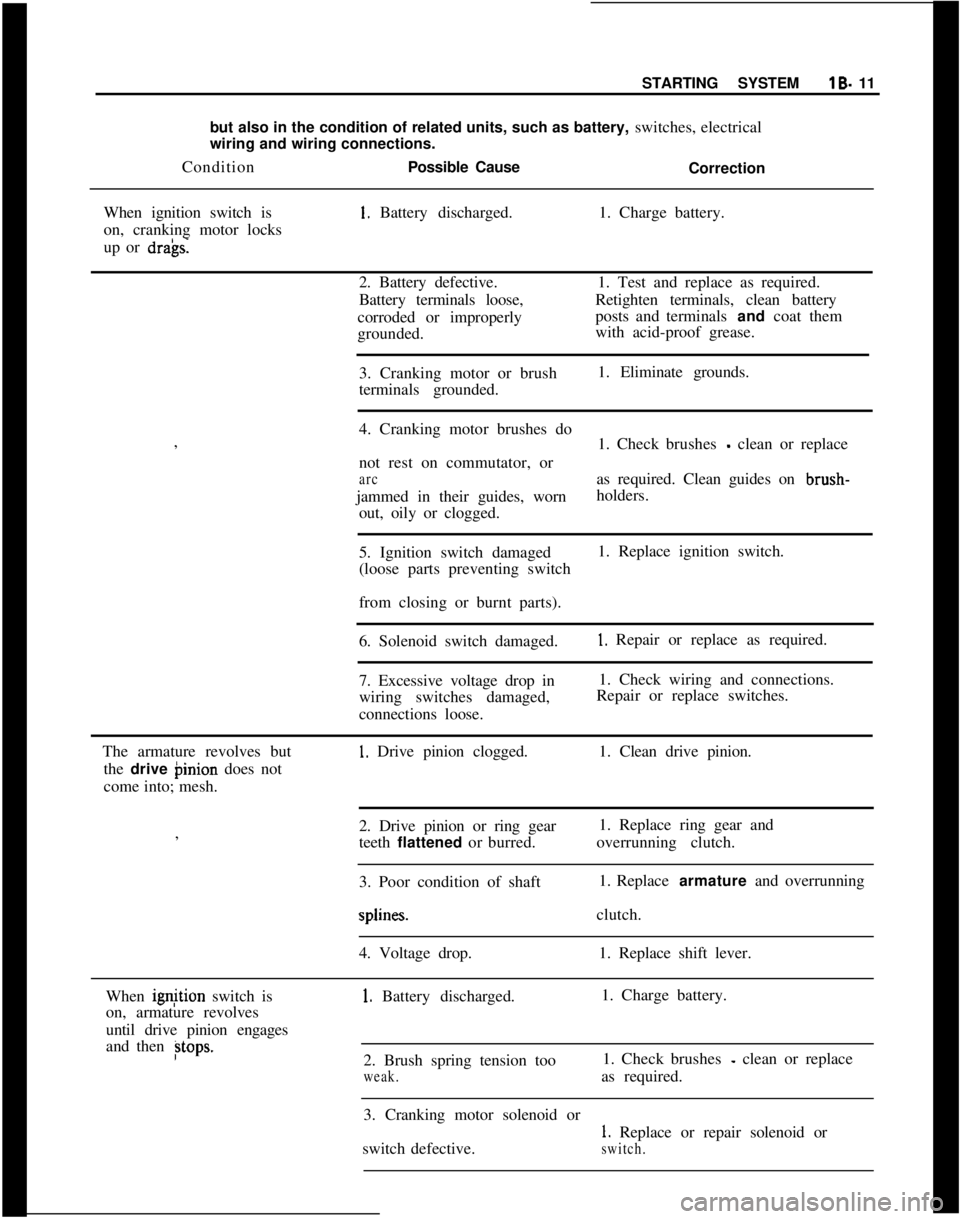
When ignition switch is1. Battery discharged.1. Charge battery.
on, cranking motor locks
up or
dra’gs.2. Battery defective.1. Test and replace as required.
Battery terminals loose,Retighten terminals, clean battery
corroded or improperlyposts and terminals and coat them
grounded.with acid-proof grease.
3. Cranking motor or brush1. Eliminate grounds.
terminals grounded.
I
4. Cranking motor brushes do
,
1. Check brushes
- clean or replace
not rest on commutator, or
arcas required. Clean guides on brush-
jammed in their guides, wornholders.
out, oily or clogged.
5. Ignition switch damaged1. Replace ignition switch.
(loose parts preventing switch
I
from closing or burnt parts).
6. Solenoid switch damaged.
1. Repair or replace as required.
7. Excessive voltage drop in1. Check wiring and connections.
wiring switches damaged,Repair or replace switches.
connections loose.
The armature revolves but
1. Drive pinion clogged.1. Clean drive pinion.
the drive binion does not
come into; mesh.
2. Drive pinion or ring gear1. Replace ring gear and
,
teeth flattened or burred.overrunning clutch.
I
3. Poor condition of shaft1. Replace armature and overrunningsplines.clutch.
4. Voltage drop.1. Replace shift lever.
When ignjtion switch is
1. Battery discharged.1. Charge battery.
on, armature revolves
until drive pinion engages
and then
Btops.2. Brush spring tension too1. Check brushes - clean or replace
weak.as required.
3. Cranking motor solenoid or
1. Replace or repair solenoid or
switch defective.
switch.
Page 33 of 625
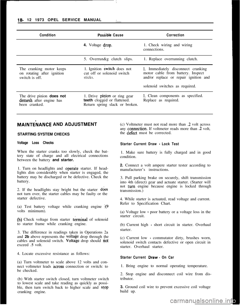
19- 12 1973 OPEL SERVICE MANUAL :ConditionPosiible CauseCorrection4. Voltage drop.1. Check wiring and wiring
connections.
5. Overrun&g clutch slips.1. Replace overrunning clutch.
The cranking motor keeps
on rotating after ignition
switch is off.1. Ignition
{witch does not
cut off or solenoid switch
sticks.
1, Immediately disconnect cranking
motor cable from battery. Inspect
and/or replace or repair ignition and
solenoid switches as required.
The drive pinion does notdemesh after engine has
been cranked.1. Drive pinion or ring gear
1. Clean components as specified.
teeth clogged or flattened.Replace as required.
Return spring slack or broken.MAlNTEilANCE AND ADJUSTMENT
/
STARTING SYSTEM CHECKS
Voltage Loss ChecksWhen the starter cranks too slowly, check the bat-
tery state of charge and all electrical connections
between the battery and starter.
1. Turn on headlights and
opera’te starter. If head-
lights dim considerably when starter is engaged, the
battery may be discharged or be defective. Check the
battery.
2. If the headlights stay bright but the starter d&s
not turn over, the starter cables may be faulty or the
starter defective.
(a) Test battery voltage while cranking engine
1(9volts minimum).
(b) Check voltage from starter tkrminal of solenoid
to starter frame while cranking engine.
3. The difference in readings taken in Operations 2a
and 2b above represents the
volt& drop through the
cables and solenoid switch. Voltdge drop should
Gotexceed
.5 volt.
4. Locate excessive resistance as follows:
(a) Turn voltmeter to scale above 12 volts and con-
nect voltmeter leads
across connection or switch: to
be checked.
(b) With starter switch closed, turn voltmeter switch
to lowest scale and take reading as quickly as possi-
ble, then turn switch back to higher scale and stop
cranking engine.(c) Voltmeter must not read more than
.2 volt across
any
c:onnection. If voltmeter reads more than .2 volt,
the
d~efect must be corrected.
Starter Current Draw - Lock Test1. Make sure battery is fully charged and in good
condition.
2. Connect a volt ampere starter tester according to
manufacturer’s instructions.
3. Pull parking brake on securely, shift transmission
into 4th (direct) gear and actuate starter. (Starter will
not
t,urn engine because engine is locked through
transmission.)
4. While starter is actuated, read voltage and current.
Refer to Specification Chart.
(a) Voltage low
_ poor battery or a voltage loss in the
starter circuit.
(b) Current high
- short circuit in starter. Overhaul
starter.
(c) Current low
- commutator dirty, brushes worn,
solenoid switch contacts defective or open circuit in
starter. Overhaul starter.
Starter Current Draw. On Car1. Bring engine to normal operating temperature.
2. Stop engine and disconnect coil wire from dis-
tributor.
3. Ground coil wire to prevent excessive coil voltage
build up.
Page 34 of 625
STARTING SYSTEMlB- 13
4. Connect test equipment and, with transmission in
neutral, turn engine over until voltage stabilizes.
Note read.ings.5. Current draw should be between 90-130 amperes.
I3. Remove end frame from field frame and pull both
insulating tubes out of field frame.
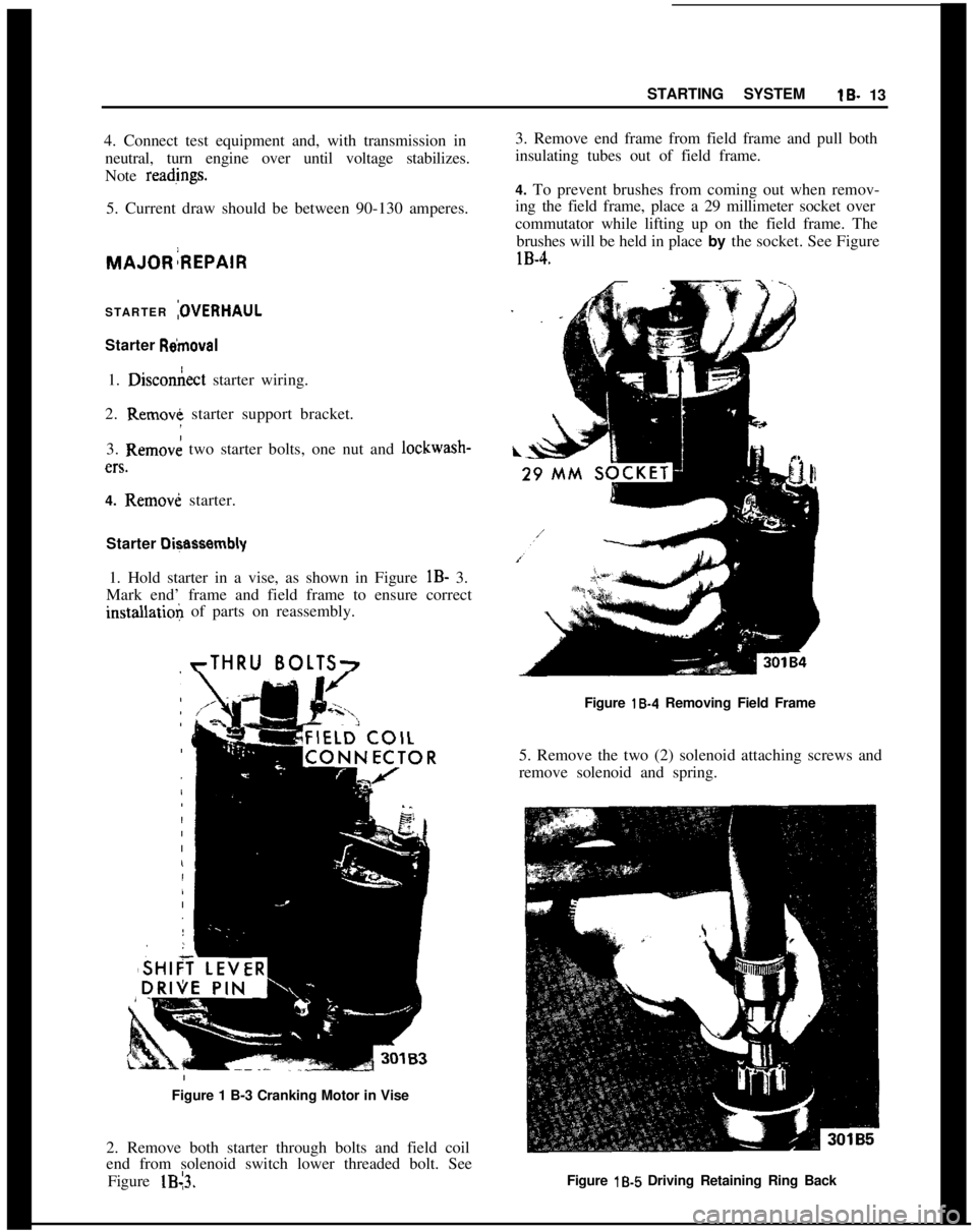
4. To prevent brushes from coming out when remov-
ing the field frame, place a 29 millimeter socket over
commutator while lifting up on the field frame. The
brushes will be held in place by the socket. See FigurelB-4.
STARTER
:OVERHAULStarter
R&~moval1.
Dixon&t starter wiring.
2. Remove starter support bracket.
3. Removk two starter bolts, one nut and lockwash-en.
4. Removi starter.
Starter
Di+assembly1. Hold starter in a vise, as shown in Figure
lB- 3.
Mark end’ frame and field frame to ensure correctinstallatioli of parts on reassembly.
rTHRU BOLTS7Figure
18-4 Removing Field Frame
5. Remove the two (2) solenoid attaching screws and
remove solenoid and spring.
Figure 1 B-3 Cranking Motor in Vise
2. Remove both starter through bolts and field coil
end from solenoid switch lower threaded bolt. See
Figure lB13.Figure
lb5 Driving Retaining Ring Back
Page 35 of 625
lB- 14 1973 OPEL SERVICE MANUAL !
6. Remove shift lever shaft and: lift armature aid
shift lever assembly.
7. Drive back retaining ring on armature shaft. See
Figure
lB-5.
8. Take the lock ring, retaining ring, and
over&-
ning clutch and pinion off armature shaft. Cheqk
groove in shaft for burrs and remove with a soft tile.
Cleaning and Inspecting Parts
1. Clean and check all parts. Replace defective parts.
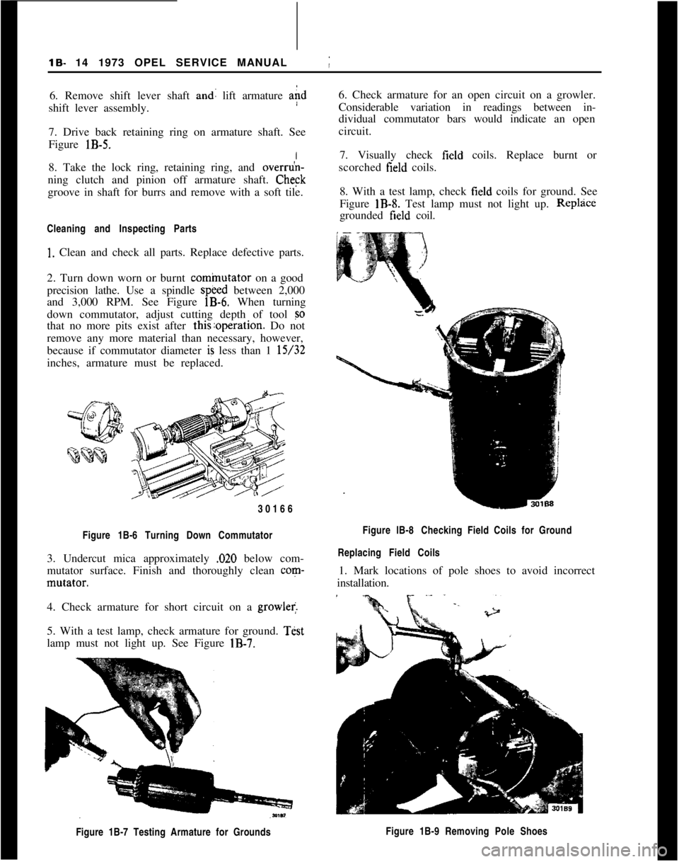
2. Turn down worn or burnt
cominutator on a good
precision lathe. Use a spindle
speed between 2,000
and 3,000 RPM. See Figure
lB-6. When turning
down commutator, adjust cutting depth of tool
so
that no more pits exist after this:operation. Do not
remove any more material than necessary, however,
because if commutator diameter
is less than 1 15/32
inches, armature must be replaced.
30166
Figure 1B-6 Turning Down Commutator
3. Undercut mica approximately ,020 below com-
mutator surface. Finish and thoroughly clean
corn-
mutator.
I
4. Check armature for short circuit on a
growler.
5. With a test lamp, check armature for ground.
Test
lamp must not light up. See Figure
IB-7.
Figure 1B-7 Testing Armature for Grounds
j
6. Check armature for an open circuit on a growler.
Considerable variation in readings between in-
dividual commutator bars would indicate an open
circuit.
7. Visually check
field coils. Replace burnt or
scorched
field coils.
8. With a test lamp, check
field coils for ground. See
Figure
IB-8. Test lamp must not light up. Replzice
grounded field coil.
Figure lB-8 Checking Field Coils for Ground
Replacing Field Coils
1. Mark locations of pole shoes to avoid incorrect
installation.
Figure 1B-9 Removing Pole Shoes
Page 36 of 625
STARTING SYSTEMlS- 15
2. Unscrew the four (4) pole shoe attaching bolts and
take
field coils out of field frame. See Figure lB-9.
3. To ensure proper installation of the pole shoes,
align shoes exactly parallel with the armature shaft
prior to tightening attaching bolts.
Checking
a’nd Replacing Brushes
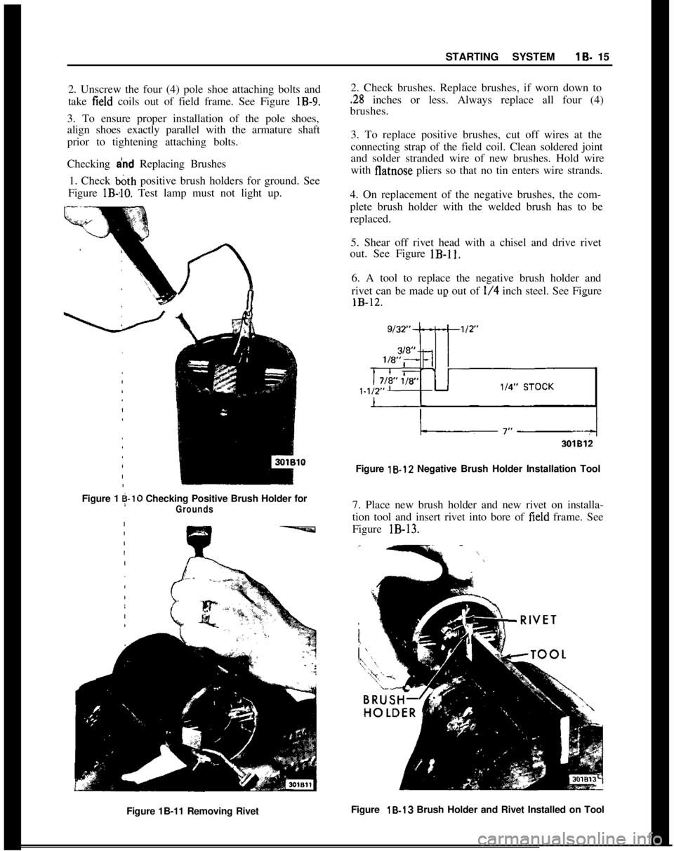
1. Check
b&h positive brush holders for ground. See
Figure
lB-,lO. Test lamp must not light up.
Figure 1g-10 Checking Positive Brush Holder forGrounds
2. Check brushes. Replace brushes, if worn down to
.28 inches or less. Always replace all four (4)
brushes.
3. To replace positive brushes, cut off wires at the
connecting strap of the field coil. Clean soldered joint
and solder stranded wire of new brushes. Hold wire
with
flatnose pliers so that no tin enters wire strands.
4. On replacement of the negative brushes, the com-
plete brush holder with the welded brush has to be
replaced. 5. Shear off rivet head with a chisel and drive rivet
out. See Figure
lB-11.
6. A tool to replace the negative brush holder and
rivet can be made up out of
l/4 inch steel. See Figure
Figure 18.12 Negative Brush Holder Installation Tool
7. Place new brush holder and new rivet on installa-
tion tool and insert rivet into bore of
field frame. See
Figure
lB-13.
Figure 1B-11 Removing Rivet Figure 18-13
Brush Holder and Rivet Installed on Tool
Page 37 of 625
lB- 16 1973 OPEL SERVICE MANUAL
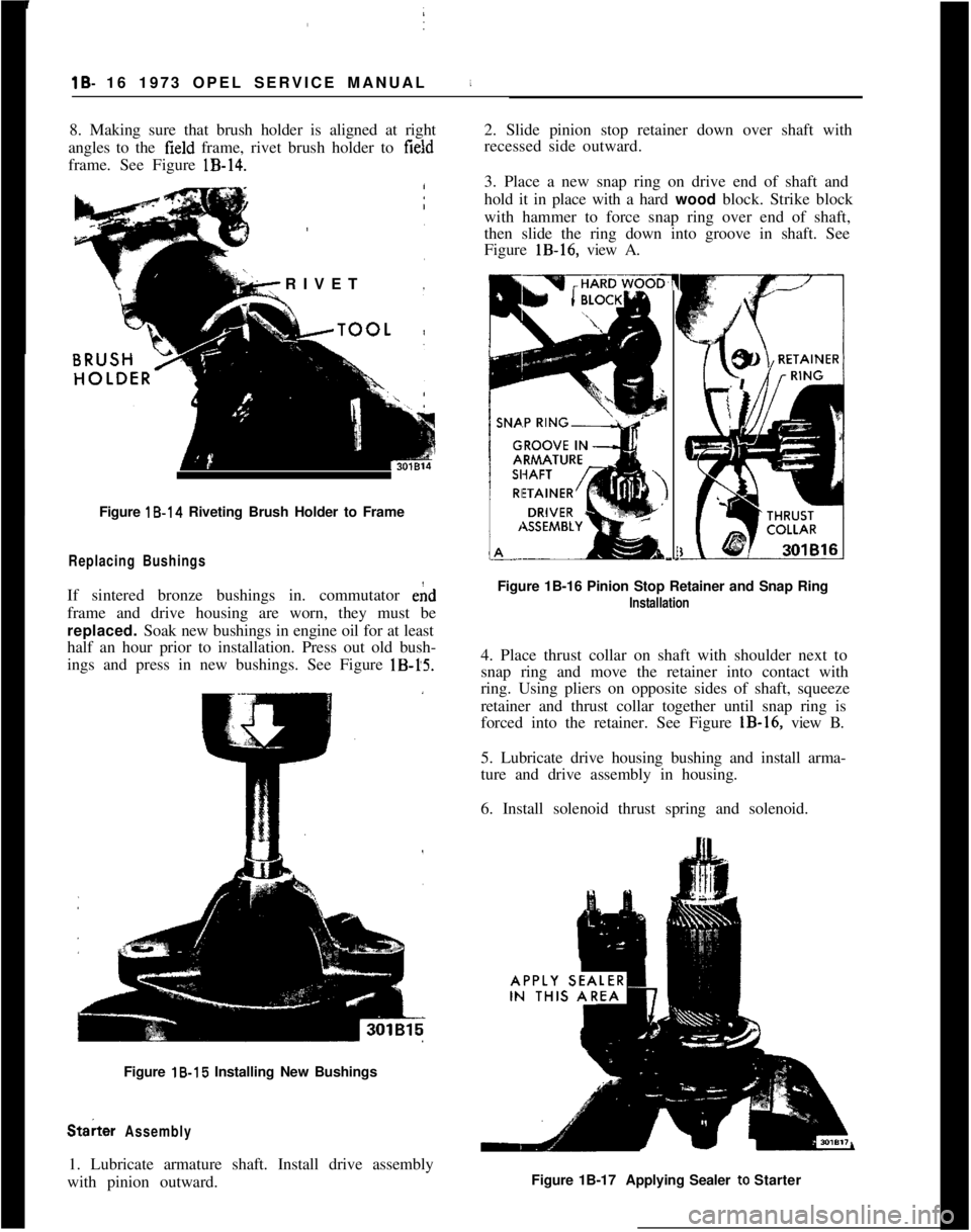
8. Making sure that brush holder is aligned at right
angles to the
field frame, rivet brush holder to field
frame. See Figure
lB-14.
RIVET
Figure 18.14 Riveting Brush Holder to Frame i
Replacing Bushings
If sintered bronze bushings in. commutator ehd
frame and drive housing are worn, they must be
replaced. Soak new bushings in engine oil for at least
half an hour prior to installation. Press out old bush-
ings and press in new bushings. See Figure
lB-15.
Figure 18.15 Installing New Bushings
St& Assembly
1. Lubricate armature shaft. Install drive assembly
with pinion outward. 2. Slide pinion stop retainer down over shaft with
recessed side outward.
3. Place a new snap ring on drive end of shaft and
hold it in place with a hard
wood block. Strike block
with hammer to force snap ring over end of shaft,
then slide the ring down into groove in shaft. See
Figure
lB-16, view A.
7
(
I
I
E-.
Figure 1B-16 Pinion Stop Retainer and Snap Ring
Installation
4. Place thrust collar on shaft with shoulder next to
snap ring and move the retainer into contact with
ring. Using pliers on opposite sides of shaft, squeeze
retainer and thrust collar together until snap ring is
forced into the retainer. See Figure
lB-16, view B.
5. Lubricate drive housing bushing and install arma-
ture and drive assembly in housing.
6. Install solenoid thrust spring and solenoid.
Figure 1B-17 Applying Sealer to Starter
Page 38 of 625
STARTING SYSTEMlB- 17
7. Seal area between solenoid and frame. See FigurelB-17.
8. With brushes and spring in housings held in place
with a 29 @llimeter socket, slide frame assembly in
position.
9. Install i+ulating sleeves in field frame.
10. Install knd frame and replace through bolts and
tighten bolts.
11. Install bolt holding field frame to solenoid.
SPEClFltjATlONS
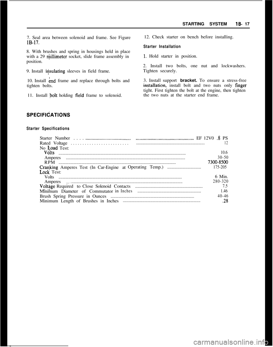
Starter SpecificationsStarterNumber. . . .
.._.._..._...........................RatedVoltage
. . . . . . . . . . . . . . . . . . . . . . . . .No voad Test:
...............................................EF 12V0 .8 PS
.....................................................................12Volts
................................................................................................................................10.6Amperes
........................................................................................................................30-50RPM
......................................................................................................................7300-8500Cranking Amperes Test (InCar-Engine atOperating Temp.)
..................................175-205
Lock Test:
Volts
............................................................................................................................6 Min.
Amperes
....................................................................................................................280-320Volt$geRequiredtoCloseSolenoidContacts
....................................................................7.5MinimumDiameterof Commutatorin
Inches................................................................1.46Brush Spring Pressure in Ounces
....................................................................................40-46Minimum Length of Brushes in Inches...............................................................................2812. Check starter on bench before installing.
Starter Installation
1. Hold starter in position.
2. Install two bolts, one nut and lockwashers.
Tighten securely.
3. Install support bracket. To ensure a stress-freeintitallation, install bolt and two nuts only finger
tight. First tighten the bolt at the engine, then tighten
the two nuts at the starter end frame.
Page 39 of 625
1 C- 18 1973 OPEL SERVICE MANUAL
IGNITIPN SYSTEM
CbNTENTS
Subject
DESCRIPTION AND OPERATION: Ignition System ..................................................................
Ignition
Switc,h....................................................................
Ignition Coil
..........................................................................\
Distributor
............................I...............................................
DIAGNOSIS: (Not Available)
MAINTENANCE AND ADJUSTMENTS: Contact PointReplacement ............................................
Dwell Angle Adjustment :
................................................
Ignition Timing Adjustment ..........................................
Ignition Wire Inspection :
..................................................
Check Ignition Output ......................................................
Check Distributor
..............................................................
Check Spark Plugs
............................................................
MAJOR REPAIR: Distributor Removal ..........................................................
Disassembly ........................
I...............................................
Reassembly
..........................I...............................................
Distributor Installation
....................................................
SPECIFICATIONS: /
Ignition
Coil ..........................................................................
Distributor
....‘........................i...............................................
Spark Plugs ........................................................................\
..
DESCRIPTION AND OPERATION
INGITION SYSTEM
The ignition system basically consists of an ignitipn
switch, ignition coil, distributor, battery and related
wiring. The ignition switch is located in the steering
column, the ignition coil is located left front inner fender
skirt and the distributor is located at the left
front of the engine.
IGNITION SWITCH
The combined ignition switch and steering lock ian
be switched to any one of the below listed positions.
Insert key with notch pointing upward.
Page No.
lC-18
lC-18
lC-19
lC-19
1 c-20
1 c-20
1 c-20
lC-21 r
lC-21
1 c-22
1 c-22
1 r-23
1 C-23
1 c-24
1 C-25
1 C-26
1 C-26
1 C-26
(Fully counterclockwise) Lock position. Ignition
locked, steering locked, only with key removed.
Electrical circuits disconnected except to main light-
ing switch and dome lamp. The
key can be removed.
0- (First position clockwise from lock) Garage posi-
tion. ‘The key and lock assembly must be pushed “in”
to reach this position from lock. The steering is un-
locked and the ignition is off. The electrical circuits
are the same as in lock position. The key cannot be withdrawn.
l- [Chposition.) All electrical circuits controlled by
ignition switch are completed through the switch.
The key cannot
be removed while switch is in drive
position.
Page 40 of 625
IIIGNITION SYSTEMlC- 19
11. (Startx position.) The ignition key must be
released as soon as engine starts. The switch then
returns aujomatically to the on position.
IGNITION
GOILThe ignition coil consists of a laminated non- mag-
netic iron
(core enclosed by two coils; the primary
winding and the secondary winding.
The prim+y circuit consists of the power source
(battery), the ignition switch, the ignition coil pri-
mary winding, the distributor breaker points with
ignition condenser connected in parallel, and all con-
necting
lo& tension wiring.
The secondary circuit consists of the ignition coil
secondary ‘winding, the spark plugs, all connecting
high tens@ wiring, the distributor cap and the
ro-tor.
When the’ ignition switch is turned on and the
breaker pdints are closed, current flows through the
ignition
c&l primary winding and produces a mag-
netic field wound the coil windings.
When the breaker points are separated by the revolv-
ing distributor cam, the magnetic field collapses and
induces a high voltage surge in the secondary wind-
ing,
produ;cing a spark between the spark plug elec-
trodes. ,
The ignitidn condenser which is connected in paral-
lel with the breaker points, prevents arcing between
the
separa’ted breaker contacts, and current flow
after~ the breaker points have been separated, thus
causing a kery rapid collapse of the magnetic field
around th$ Ignition coil.
/
IGNITION ‘DISTRIBUTORThe ignitidn distributor breaks the primary current,distributeslthe high voltage surges induced in the coil
secondary winding to the spark plugs according to
the engin< tiring order and sets ignition timing in
relation to. engine RPM and load.
The housi+g of the distributor contains the centrifu-
gal advance mechanism and the movable breaker
plate with’s breaker lever and contact support. The
vacuum advance mechanism is attached to the
breaker plate and mounted on the outside of the
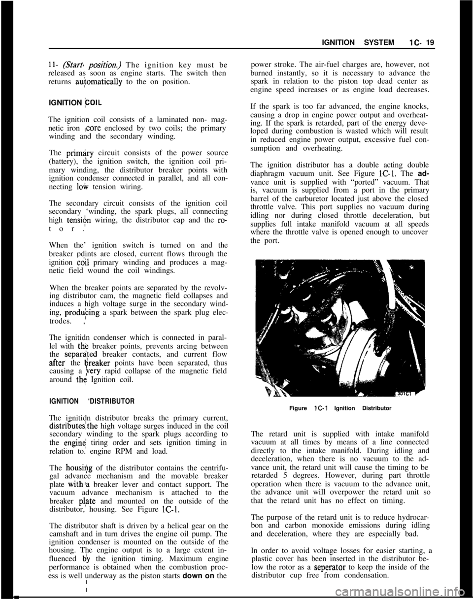
distributor, housing. See Figure lC-1.
The distributor shaft is driven by a helical gear on the
camshaft and in turn drives the engine oil pump. The
ignition condenser is mounted on the outside of the
housing. The engine output is to a large extent in-
fluenced b) the ignition timing. Maximum engine
performance is obtained when the combustion proc-
ess is well underway as the piston starts down on thepower stroke. The air-fuel charges are, however, not
burned instantly, so it is necessary to advance the
spark in relation to the piston top dead center as
engine speed increases or as engine load decreases.
If the spark is too far advanced, the engine knocks,
causing a drop in engine power output and overheat-
ing. If the spark is retarded, part of the energy deve-
loped during combustion is wasted which will result
in reduced engine power output, excessive fuel con-
sumption and overheating.
The ignition distributor has a double acting double
diaphragm vacuum unit. See Figure lC-1. The ad-
vance unit is supplied with “ported” vacuum. That
is, vacuum is supplied from a port in the primary
barrel of the carburetor located just above the closed
throttle valve. This port supplies no vacuum during
idling nor during closed throttle deceleration, but
supplies full intake manifold vacuum at all speeds
where the throttle valve is opened enough to uncover
the port.
Figure lC-1 Ignition Distributor
The retard unit is supplied with intake manifold
vacuum at all times by means of a line connected
directly to the intake manifold. During idling and
deceleration, when there is no vacuum to the ad-
vance unit, the retard unit will cause the timing to be
retarded 5 degrees. However, during part throttle
operation when there is vacuum to the advance unit,
the advance unit will overpower the retard unit so
that the retard unit has no effect on timing.
The purpose of the retard unit is to reduce hydrocar-
bon and carbon monoxide emissions during idling
and deceleration, where they are especially bad.
In order to avoid voltage losses for easier starting, a
plastic cover has been inserted in the distributor be-
low the rotor as a seperator to keep the inside of the
distributor cup free from condensation.