OPEL GT-R 1973 Service Manual
Manufacturer: OPEL, Model Year: 1973,
Model line: GT-R,
Model: OPEL GT-R 1973
Pages: 625, PDF Size: 17.22 MB
OPEL GT-R 1973 Service Manual
GT-R 1973
OPEL
OPEL
https://www.carmanualsonline.info/img/37/57410/w960_57410-0.png
OPEL GT-R 1973 Service Manual
Trending: open hood, alternator, transmission, air bleeding, clutch, recommended oil, turn signal
Page 421 of 625
7C- 601973 OPEL SERVICE MANUAL
c. DRIVE RANGE. SECONO GEAROrive Range . Second Gear
Reverse Clutch - Released
Second Clutch -Applied
Sprag
- Overrunning
In Drive Range. Second Gear, the low band and second clutch are applied.Third Clutch
- Released
Low Band -Applied
The input shaft drives the third clutch drum and the second clutch composition plates. When the second clutch
piston is applied, the rotating second clutch composition plates are locked
w the second clutch steel plates. Since
the second clutch drum is now rotating in a clockwise direction, the ring gear is driven clockwise. As described in
“Principles of Operation”, the carrier is driven in a clockwise direction. The long planet pinions also drive the
short planet pinions, which drive the input sun gear clockwise, causing the sprag assembly to overrun. The ratio
is 1.48:1.
second Range
In Second Range, the Power flow is exactly the seme as drive range - second gear.7c50
Figure
7C-50 Drive Range - Second Gear
Page 422 of 625
AUTOMATIC TRANSMISSION 7C- 61
d. DRIVE RANGE - THIRD GEAR
Drive Range
- Third Gear
Reverse Clutch
- Released
Second Clutch. Applied
Sprag . LockedThird Clutch -Applied
Low Band
- Released
In Drive Range
- Third Gear, the low band is released and both the second and third clutches are applied.
In this condition, the ring gear is locked o the input sun gear. With two planetary members connected
inthismanner, the entire planetary system will rotate as a solid unit and provide a direct drive with a ratio of 1 to 1. The
input is split between the ring gear end input sun, and the rarrier is the output member.
Figure 7C-5 1 Drive Range Third Gear
Page 423 of 625
Third Clutch -Applied
Low Band. Released
Page 424 of 625
AUTOMATIC TRANSMISSION ?C- 63
Page 425 of 625
712.641973 OPEL SERVICE MANUALHYDRAULIC OPERATION
‘Irn
Page 426 of 625

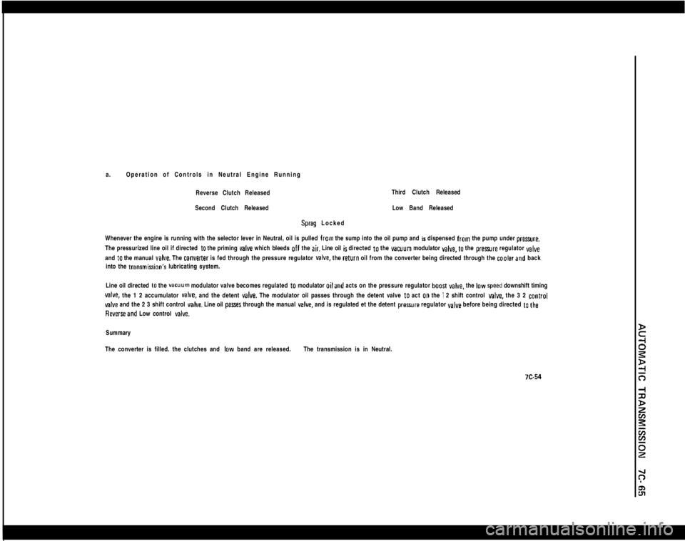
a.Operation of Controls in Neutral Engine Running
Reverse Clutch ReleasedThird Clutch Released
Second Clutch ReleasedSprag LockedLow Band Released
Whenever the engine is running with the selector lever in Neutral, oil is pulled from the sump into the oil pump and is dispensed from the pump under preure.
The pressurized line oil if directed
to the priming valve which bleeds off the air. Line oil is directed to the vacuum modulator YBIYB, to the prexwre regulator valveand
to the manual veIve. The converter is fed through the pressure regulator MIYB. the return oil from the converter being directed through the coalerand back
into the transmisGon’s lubricating system.
Line oil directed
to the vacuum modulator valve becomes regulated to modulator oiland acts on the pressure regulator boosI YBCB. the IDW speed downshift timing
valve. the 1 2 accumulator MIYB. and the detent valve. The modulator oil passes through the detent valve to act 00 the I 2 shift control give. the 3 2 control
valve and the 2 3 shift control valve. Line oil pasres through the manual v&e. and is regulated et the detent preaure regulator valve before being directed to the
Reverseand Low control delve.Summary
The converter is filled. the clutches and
IDW band are released.The transmission is in Neutral.
Page 427 of 625
7C- 66
1973 OPEL SERVICE MANUAL
Page 428 of 625
Page 429 of 625
7C- 681973 OPEL SERVICE MANUAL
II III-
--
Page 430 of 625

c. Operation of Controls in Drive Range Second Gear
Reverse Clutch
ReleasedThird Clutch Released
Second Clutch AppliedLow Band Applied
Sprag Over Running
As the vehicle increws speed. the govwnor
allow more drive oil 10 pass through, and this increased pressure, acting on the end of the 1 2 shift
vahre. overcomes the I 2 shift valve spring pressure and allovn drive oil 10 pasr through the valve to feed the second clutch oil parsages.Second clutch oil passes through the second clutch orifice control valve, seating the ball and is metered to the second clutch piRon
to begin to apply
the second clutch, whileportion of the oil is directed
10 the accumulator. As the upper portion of the accumulator fills with second clutch oil. itovercomes the leer prewre of 1 2 accumulator oil and spring at the bottom of the accumulator piston. forcing the piston downward. The upper
portion of the accumulator is now filled, allowing full oil preaure
to the second clutch piEton far the final apply. The accumulator, therefore, acts as a
reservoir
10 produce a damping effect for a smooth second clutch apply and the 1 2 shift.
Second clutch oil from the 1 2 shift
valve is simultaneously directed to the 2 3 shift valve to be used as the oil source for the 2 3 shift.
Summary
The second clutch is on. the band is on, the transmission is in drive range
i second gear.
Trending: mirror controls, wiper size, steering wheel, headlights, headlamp, maintenance, Torque


