OPEL GT-R 1973 Service Manual
Manufacturer: OPEL, Model Year: 1973, Model line: GT-R, Model: OPEL GT-R 1973Pages: 625, PDF Size: 17.22 MB
Page 391 of 625

78.301973 OPEL SERVICE MANUAL
SHOULDER OR
SHIFTE
.44Figure 78-46 Installing Reverse Shifter Fork
Figure 78.44 Mainshaft Assembly Secured Into Rear
Bearing Retainer by Snap Ring
16. Place front synchronizer spring in the gear shifter
sleeve carrier. Install (3) third and fourth speed shoes
(short design) and gear shifter sleeve over gear shifter
sleeve carrier along with synchronizer cover. Arrows
on shoes point toward rear of mainshaft. Gear shifter
sleeve yoke groove should be toward front.
17. With sealer, install new gasket onto transmission
case extension housing.
Installing Reverse Idler Gear and Reverse Gear
Shifter Shaft1. Inspect shafts carefully for burrs, and remove with
emery cloth. Burrs on shifter shaft will prevent easy
installation of shifter yoke. Lightly oil with transmis-
sion oil prior to installation. Place lock ball into
reverse idler gear shaft and push shaft through hole
in rear of case and on through reverse idler gear
which should have groove end toward front. See Fig-
ure
7B-46.Continue to drive reverse idler gear shaft forward
with plastic hammer until rear end of shaft is flush
with rear case face.
2. Position reverse speed shifter yoke in groove of
reverse idler gear and install reverse gear shifter shaft
from rear of case with notches up, pushing it through
reverse speed shifter yoke. See Figure
7B-47.3. Install spiral pin to secure yoke to shifter shaft and
drive plug into hole in rear of case.Figure 78.47 Third and Fourth Speed Shifter Shaft
Installed
Installing Mainshaft Assembly and Main Drive
Gear1. Slide mainshaft assembly into transmission case
from rear.
2. From the’front, slide mainshaft front ring and the
mainshaft needle bearing onto the mainshaft. See
Figure
7B-48.3. Install main drive gear through front of transmis-
sion case until main drive (standard part) snap ring
is flush with case.
Installing Third and Fourth Gear Shifter Shaft1. Position third and fourth speed yoke onto gear
shifter sleeve. See Figure
7B-47.2. Insert third and fourth gear shifter shaft through
hole in front of case with notches down, pushing it
through third and fourth speed yoke. Third and
Page 392 of 625

MANUAL TRANSMISSION70.31COUNTER SHAFT GEAR
THRUST WASHER\Figure 76.48 Installing Spacer Ring and Needle
Bearing Onto Mainshaft
fourth speed yoke should be positioned with rounded
notch at shaft hole portion of yoke toward rear. See
Figure 78. 47.
3. Install spiral pin, allowing
i/16” to 5/64” of pin
to protrude.
Installing First and Second Gear Shifter Shaft
1. Inspect shifter shaft carefully for burrs, and
remove with emery cloth. Burrs on shifter shaft will
prevent easy installation of shifter yoke and cam.
Lightly oil with transmission oil prior to installation.
Insert first and second gear shifter shaft through hole
in rear of case with three notches down and toward
rear of transmission, pushing shaft tirst through
firstand second gear shifter yoke, which should be posi-
tioned on first and second gear sliding gear with
shoulder toward front of case. To position first and
second gear shifter yoke on first and second gear
sliding gear, push reverse idler gear forward, engag-
ing the idler gear with the first and second gear
sliding gear. This will make room for positioningfirst and second gear shifter yoke. See Figure
7B-49.2. Continue to drive first and second gear shifter
shaft through shifter shaft cam, which should be
positioned as shown in Figure
7B-50.3. Install spiral pins to secure shifter yoke and shifter
shaft cam to first and second gear shifter shaft.
Installing Selector Shaft
1. Inspect selector shaft carefully for burrs, andFigure
78.49 Countergear Thrust Washers Installed
Figure
78-50 Position of “L” Shaped Selector Dog
remove with emery cloth. Burrs on shaft will prevent
easy installation of intermediate levers. Lightly oil
with transmission oil prior to installation. Insert new
selector shaft oil seals in holes on both sides of trans-
mission case and insert selector shaft into case and
through third, fourth, and reverse intermediate lever.
Third, fourth, and reverse intermediate lever should
be positioned on selector shaft, as shown in Figure
7B-51.2. Continue to push selector shaft through first and
second intermediate lever and through other side of
case. First and second intermediate lever should be
positioned on selector shaft, as shown in Figure 7B-
52. Selector shaft is rotated counterclockwise (when
looking from lever end of selector shaft) from work-
ing position to have spiral pin holes in shaft vertical
and in line with pin holes in intermediate levers. To
rotate selector shaft in this manner, the reverse gear
shifter shaft and its reverse speed shifter yoke must
be pushed rearward so that the reverse idler gear is
against rear of case.
Page 393 of 625

Figure 78-5 1 Position of Third, Fourth, and Reverse
Intermediate Lever on Selector Shaft
1ST. 2ND IlrFigure 78.52 Position of First and Second
Intermediate Lever on Selector Shaft
3. Install spiral pins to secure both intermediate lev-
ers to the selector shaft. Spiral pins should not be
flush with lever surface, but rather should extend up
between
l/16 and 5/64 inches.
Installing Reverse Speed Shifter Intermediate
Lever and Interlock Balls, Springs, and Plugs
1. Engage reverse speed shifter intermediate lever
with third, fourth, and reverse intermediate lever and
also in slot in reverse gear shifter shaft, and install
79-321973 OPEL SERVICE MANUAL
bedding bolt through reverse speed shifter intermedi-
ate lever and into case. Reverse speed shifter inter-
mediate lever end play on bolt should be between
,004 and .012 inches.
2. Insert both interlock balls and then springs, and
drive both interlock plugs into case holes until they
bottom in interlock plug hole seats. Grooves in plugs
will be showing.
Installing Countershaft Gear Unit
1. Coat thrust washers with ball and roller bearing
grease and stick to transmission case. Lugs of thrust
washers must fit into transmission case slots. See
Figure
7B-49.2. Turn transmission case extension housing until
gear unit countershaft bore is completely exposed.
3. Place lock ball into shaft and from the rear of the
transmission insert shaft so that thrust washer is held
in position. Hold opposite thrust washer in position
by using a short drift.
4. Insert countershaft gear unit into transmission
case. Be sure all needle bearings and both needle
bearing washers are in place.
5. Insert gear unit countershaft into gear unit and
drive shaft into transmission case while driving out
Special Tool J-2291 1. Pay attention to lock ball. See
Figure
7B-53.Figure 78-53 Installing Countergear Shaft
Installing Transmission Case Extension Housing
1. Align transmission case extension housing and
gasket and torque (3) bolts with spring washers to 21
lb. ft.
Page 394 of 625
MANUAL TRANSMISSION70-33
Installing Gearshift Interlock Ball and Gearshift
Thrust Spring1. Install gearshift interlock ball into top transmis-
sion bore and then install gearshift thrust spring.
Installing Transmission Case Cover1. Install case cover gasket, cover, and tighten
screws.
Installing Gearshift Linkages1. Install selector ring and lock nut onto selector
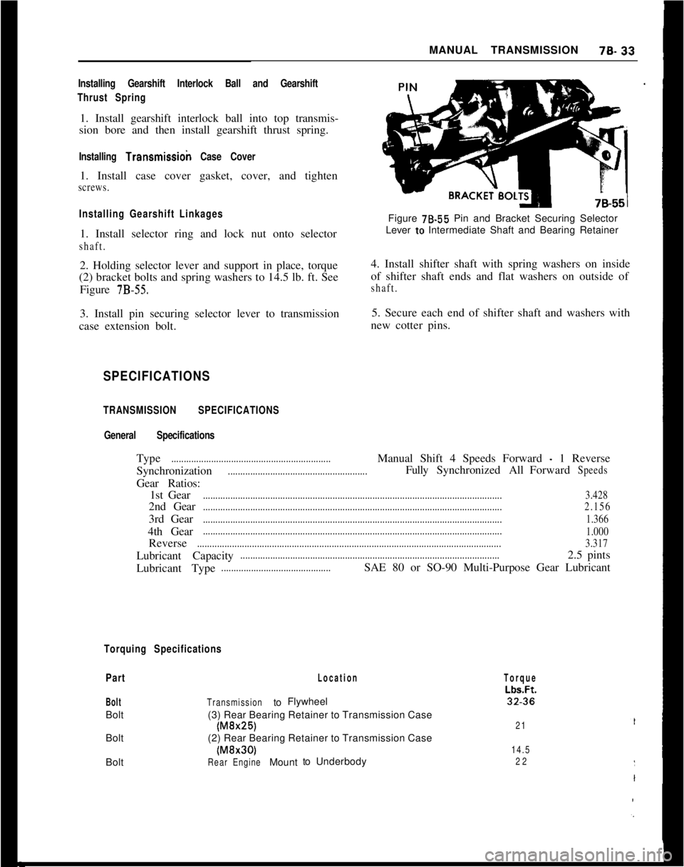
shaft.2. Holding selector lever and support in place, torque
(2) bracket bolts and spring washers to 14.5 lb. ft. See
Figure
7B-55.3. Install pin securing selector lever to transmission
case extension bolt.Figure 78.55 Pin and Bracket Securing Selector
Lever to Intermediate Shaft and Bearing Retainer
4. Install shifter shaft with spring washers on inside
of shifter shaft ends and flat washers on outside ofshaft.5. Secure each end of shifter shaft and washers with
new cotter pins.
SPECIFICATIONS
TRANSMISSION SPECIFICATIONS
General SpecificationsType
................................................................Manual Shift 4 Speeds Forward - 1 Reverse
Synchronization
........................................................FullySynchronizedAllForwardSpeedsGear Ratios:
1st Gear
........................................................................................................................3.4282nd Gear
........................................................................................................................2.1563rd Gear
........................................................................................................................1.3664th Gear
........................................................................................................................
1.000Reverse
..........................................................................................................................3.317Lubricant Capacity
........................................................................................................2.5 pints
Lubricant Type
............................................SAE 80 or SO-90 Multi-Purpose Gear Lubricant
Torquing Specifications
Part
BoltBolt
Bolt
Bolt
Location
TransmissiontoFlywheel
(3) Rear Bearing Retainer to Transmission Case
(M&25)(2) Rear Bearing Retainer to Transmission Case(MBr30)
RearEngineMounttoUnderbody
Torque
Lbs.Ft.32.36
21
14.5
22
Page 395 of 625
79.341973 OPEL SERVICE MANUAL
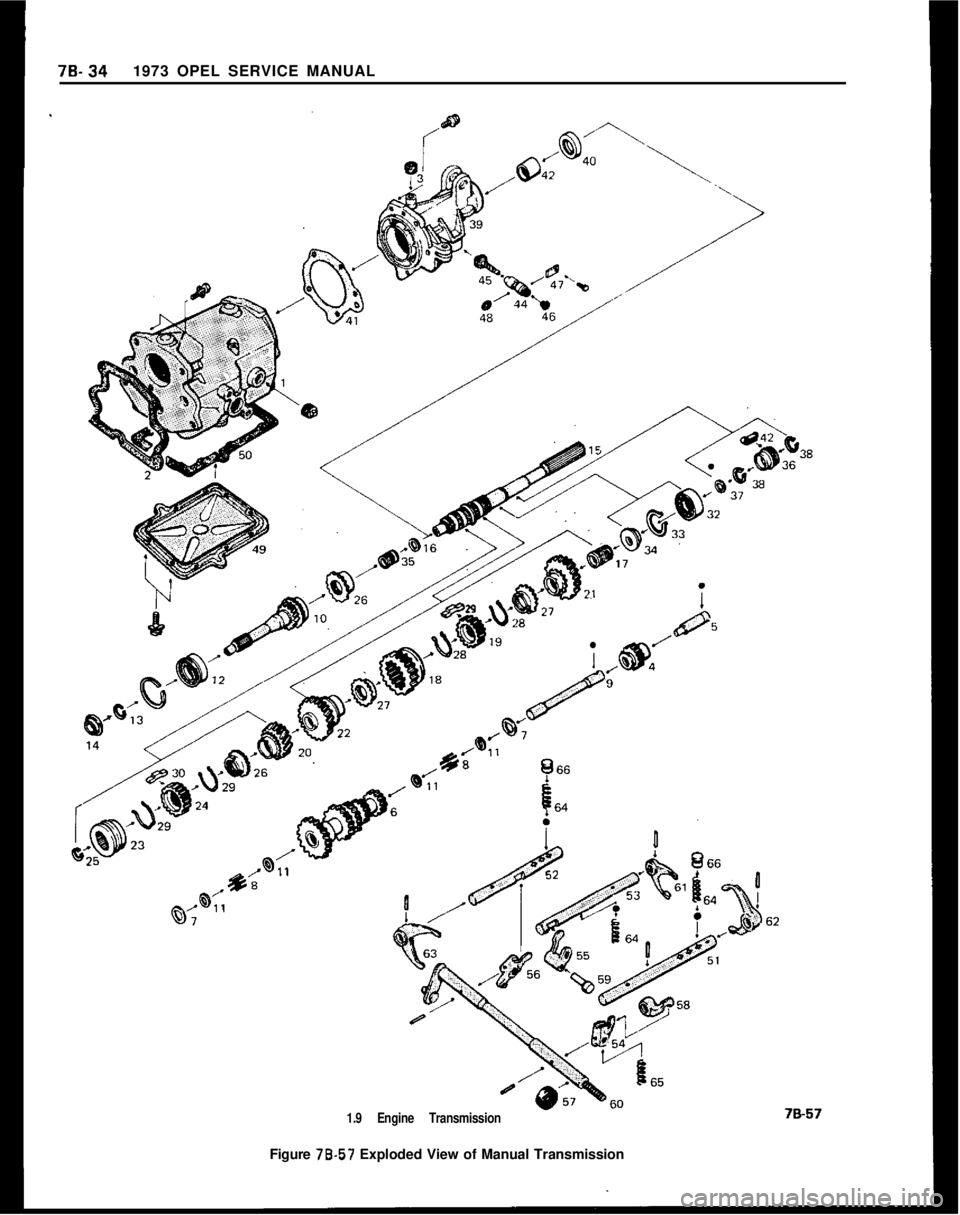
1.9 Engine TransmissionFigure 78-57 Exploded View of Manual Transmission
Page 396 of 625

tiANUAL TRANSMISSION78.35
1’ Case, Transmission
2Gasket, Trans. Case to Clutch Housing
3 Cap, Ventilator
4 Gear, W/Bushings,
ReverSe Idler
5 Shaft, Reverse Idler Gear
6 Cluster Gear, Countershaft
7Washer, Trans. Counter Gear Thrust
8Roller. Trans. Counter Gear Bearing
9 Countershaft. Cluster Gear
10 Gear, Main Drive
11Spacer Ring, Trans. Counter Gear Bearing Roller
12 Bearing, Trans. Main Shaft Pilot
13 Ring, Trans. Main Drive Gear Ball Bearing Lock
14 Seal Ring, Main Drive Gear to Clutch
15 Shaft, Main
16 Ring, Trans. Main Shaft Snap Front
17 Needle Bearing, 1st Speed Gear on Main Shaft
18 Sliding Gear, 1st and 2nd Speed
19 Guide Unit, 1st and 2nd Speeding Sliding Gear
20 Gear. 3rd Speed
2
1Gear, 1 st Speed
22 Gear, 2nd Speed
23 Sleeve, Trans. Gear Shifter
24 Carrier, Trans. Gear Shifter Sleeve
25 Snap Ring, Trans. Gear Shifter Sleeve
26 Cone, Trans. 3rd and 4th Speed Syncronizer
27 Cone, Trans. 1st and 2nd Speed Syncronizer
28 Spring, Syncronizer (1st and 2nd Speed)
29 Spring, Syncronizer
30 Shoe, 1st and 2nd Speed Shifter
31 Shoe, 3rd and 4th Speed Shifter
32 Bearing, Trans. Main Shaft R.R.
33 Snap Ring, Trans. Main Shaft Ball Bearings
34 Washer, Main Shaft Between Inner Ball Bearing
and 1st Speed Gear
3j36
37
ii40
41
42
43
44
45
46
47
48
49
50
51
52
53
54Bearing, Trans. Main Shaft Needle
- Right
Gear, Speedometer Drive
Washer, Speedo Drive Gear
Ring, Speedo Drive Gear Snap
Retainer,
R.R. Bearing
Oil Seal, Trans. R.R.
Gasket, R.R. Bearing Retainer
Bushing. Trans. Main Shaft
- R.R.
Clip, Speedo Gear
Guide, Speedo Drive
Gear, Speedo Driven
Seal, Speedo
- Shaft Sleeve
Bracket, Speedo and Guide on Trans.
Seal Ring, Speedo Drive Guide
Cover, Trans. Case
Gasket, Trans. Case Cover
Shifter Shaft, 1st and 2nd Speed
Shifter Shaft, 3rd and 4th Speed
Shaft, Reverse Speed Shifter
Intermediate Lever, 1st and 2nd Speed
Shifter
55
Lever, Reverse Shifter Intermediate
56Lever, Intermediate 3rd. 4th and Reverse
57Seal, Shifter Shaft Oil in Trans.
58Cam. on Shifter Shaft
59Shifter Shaft, Intermediate Lever Reverse
60
Shaft, W/Lever and Bolt, in Trans.
61
Fork (Yoke), Reverse Speed Shifter
62Yoke, Trans. Shifter (1st and Reverse)
63Fork (Yoke), Trans. 2nd and 3rd Speed
64
Spring, Trans. Gearshift Interlock Thrust
65
Detent Spring, Reverse Speed Gearshift
66Interlock
Plug, Gearshift Interlock Detent
Page 397 of 625

7C- 361973 OPEL SERVICE MANUAL
CONTENTS
Subject
DESCRIPTION AND OPERATION:
Description of the Opel Three-Speed Automatic,Transmission....................................................................
Principles of Operation....................................................
ComponentOperation
andLocation............................
Mechanical Operation......................................................
Hydraulic Control Units and Valves............................H,y&aulic Operation..........................................................
DIAGNOSIS:
Sequence for Trouble Diagnosis..................................
Checking
Procedures........................................................
ExternalOil
Leaks..............................................................
Trouble
DiagnosisChart..................................................
Hydraulic Pressure
Checks............................................
MAINTENANCE AND ADJUSTMENTS:
Detent Cable Adjustment..............................................
ServicingSelector
Lever..................................................
MAJOR REPAIR:
Transmission Removal and Installation
AllModels........................................................................
Removalof
OilPan............................................................
RemovalofValveBody....................................................
Removalof
ServoPiston................................................
Removalof
Selector
LeverandShaft........................
RemovalofModulatorAssembly..................................
RemovalofDetentValveAssembly............................
RemovalofExtensionHousing......................................
Removal of Speedometer Drive Gear, Governor
Body and Governor Hub..............................................
Removal of Converter Housing, Oil Pump, Reverse
and Second Clutch Assembly..................................
Removal of Third Clutch Assembly, Planetary
Carrier Assembly, Reaction Sun Gear and Drum
Assembly and Low Bank............................................
Disassembly, Inspection and Reassembly of
Converter Housing, Oil Pump and Reverse Clutch
Disassembly, Inspection and Reassembly of
SecondClutch
................................................................
Disassembly, Inspection and Reassembly of
ThirdClutch....................................................................
Disassembly, Inspection and Reassembly of
Planetary Carrier
............................................................Page No.7c- 377c- 387c- 447c- 487c- 487c- 64
7C- 81
7C- 81IC- 817c- 827c- 877c- 917c- 937c- 947c- 99.7c- 99
7c-1007c-loo
7&l 01
7c-102
7c-102
7c-103
7c-103
7c-104
7c-105
7c-111
7c-114
7c-118
Page 398 of 625
AUTOMATIC TRANSMISSION7c- 37
Disassembly, Inspection and Reassembly of
ReactionSunGearandDrum....................................
Disassembly, Inspection and Reassembly of
Governor Body................................................................
Disassembly, Inspection and Reassembly of
GovernorHub..................................................................
Disassembly, Inspection and Reassembly of
ExtensionHousing........................................................
Disassembly, Inspection and Reassembly of
Servo Piston....................................................................
Disassembly, Inspection and Reassembly of
ValveBody........................................................................
Disassembly, Inspection and Reassembly of
Case....................................................................................
InspectingandTestingConverter................................
InstallationofSelectorLeverandShaft....................
InstallationofLowBand................................................
Installation of Reaction Sun Gear and Drum..........
Installation of Output Shaft and Planetary
Carrier................................................................................
Installation of Second and Third Clutch Assemblies
IntoCase..........................................................................
InstallationofReverseClutch......................................
DeterminingSelectiveWasherSize............................
Installation of Converter Housing, Oil Pump and
Clutch Assembly............................................................
Installation of Governor Assembly..............................
InstallationofExtensionHousing................................
InstallationofSpeedometerDrivenGear..................
Installation of Detent Valve, Modulator Valve
and Modulator Assembly............................................
Installation and Adjustment of Servo........................
InstallationofValveBody..............................................
InstallationofOilPanandGasket..............................
Torque Converter..............................................................
SPECIFICATIONS:
GeneralSpecifications......................................................
7c.
7c-
,l
‘118
197c-1207c-1207c-1207C-121
7C-124
7C-125
7C-125
7C-125
7C-127
7C-127
7C-127
7C-128
7C-129
7C-129
7C-129
7c-130
7c-131
7c-131
7c-131
7C-132
7c-133
7c-134
7c-134DESCRIPTION AND OPERATION
DESCRIPTIONThe Opel Three-Speed Automatic is a fully auto-matic unit utilizing a torque converter and a Ravig-neaux planetary gear set, with three multiple disc
clutches and a single band to provide three forward
speeds and reverse. See Figure 7C-71. Automatic
upshifts and downshifts are controlled by road speed,
engine vacuum and an accelerator pedal connection
to the transmission.
Page 399 of 625
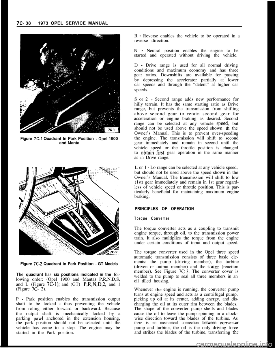
Figure 7C-1 Quadrant In Park Position -Opel 1900
and Manta7C- 381973 OPEL SERVICE MANUAL
R
- Reverse enables the vehicle to be operated in a
reverse direction.
N
- Neutral position enables the engine to be
started and operated without driving the vehicle.
D
- Drive range is used for all normal driving
conditions and maximum economy and has three
gear ratios. Downshifts are available for passing
by depressing the accelerator partially at lower
car speeds and through the “detent” at higher car
speeds.
S or 2
- Second range adds new performance for
hilly terrain. It has the same starting ratio as Drive
range, but prevents the transmission from shifting
above second gear to retain second gear for
acceleration or engine braking as desired. Second
range can be selected at any vehicle speed, but
should not be used above the speed shown m the
Owner’s Manual. This is to prevent over-speeding
the engine. The transmission will shift to second
gear immediately and remain in second until the
vehicle speed or the throttle position is changed
to obtajn first gear operation in the same manner
as in Drive range.
L or 1
- Lo range can be selected at any vehicle speed,
but should not be used above the speed shown in the
Owner’s Manual. The transmission will shift to low
(1st) gear immediately and remain in 1st gear regard-
less of vehicle speed or throttle position. This is par-
ticularly beneficial for maintaining maximum engine
braking.
PRINCIPLES OF OPERATION
Torque ConverterThe torque converter acts as a coupling to transmit
engine torque, through oil, to the transmission power
train. It also multiplies the torque from the engine
under certain conditions of input and output speed.
Figure
7C-2 Quadrant in Park Position - GT Models
The quadrant has six positions indicated in the fol-
lowing order: (Opel 1900 and Manta) P,R,N,D,S,
and L (Figure
7C-1); and (GT) P,R,N,D,2, and 1
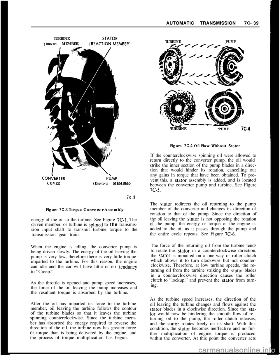
(Figure 7C- 2).The torque converter used in the Opel three speed
automatic transmission consists of three basic ele-
ments: the pump (driving member), the turbine
(driven or output member) and the stator (reaction
member). See Figure
7C-3. The converter cover is
welded to the pump to seal all three members in an
oil tilled housing.
P
- Park position enables the transmission output
shaft to be locked
- thus preventing the vehicle
from roling either forward or backward. Because
the output shaft is mechanically locked by a
parking
paw1 anchored in the extension housing,
the park position should not be selected until the
vehicle has come to a stop. The engine may be
started in the Park position.Whenever the engine is running, the converter pump
turns at engine speed and acts as a centrifugal pump,
picking up oil at its center, adding energy, and dis-
charging the oil at its outer rim between the blades.
The shape of the converter pump shells and blades
cause the oil to leave the pump spinning in a clock-
wise direction toward the blades of the turbine. Asthere is no mechanical connection between converterpump and turbine, the oil is the only driving force
and strikes the blades of the turbine, transferring the
Page 400 of 625
AUTOMATIC TRANSMISSION7c- 39
TURBINESTATOR
(DRIVEN MEMBER)fREACTION
MEMBER)CON;ERTER
COVERP;MP
(DRIVING MEMBER)
7c.3Figure
7C-3 Torque Converter Assembly
energy of the oil to the turbine. See Figure
7C-1. The
driven member, or turbine is splined to the transmis-
sion input shaft to transmit turbine torque to the
transmission gear train.
When the engine is idling, the converter pump is
being driven slowly. The energy of the oil leaving the
pump is very low, therefore there is very little torque
imparted to the turbine. For this reason, the engine
can idle and the car will have little or no tendancy
to “Creep.”
As the throttle is opened and pump speed increases,
the force of the oil leaving the pump increases and
the resultant torque is absorbed by the turbine.
After the oil has imparted its force to the turbine
member, oil leaving the turbine follows the contour
of the turbine blades so that it leaves the turbine
spinning counterclockwise. Since the turbine mem-
ber has absorbed the energy required to reverse the
direction of the oil, the turbine now has greater forceor torque than is being delivered by the engine, and
the process of torque multiplication has begun.TURBINE
PUMPTURBINE
PUMP7c4Figure
7C-4 Oil Flow Without Stator
If the counterclockwise spinning oil were allowed to
return directly to the converter pump, the oil would
strike the inner section of the pump blades in a direc-
tion that would hinder its rotation, cancelling out
any gains in torque that have been obtained. To pre-
vent this, a stator assembly is added, and is located
between the converter pump and turbine. See Figure7c-5.
The stator redirects the oil returning to the pump
member of the converter and changes its direction of
rotation to that of the pump. Since the direction of
the oil leaving the stator is not opposing the rotationof the pump, the energy or torque of the engine is
added to the oil as it passes through the
the entire cycle repeats. See Figure
7C-6.pump and
The force of the returning oil from the turbine tends
to rotate the stator in a counterclockwise direction,
the stator is mounted on a one-way or roller clutch
which allows it to turn clockwise but not counter-
clockwise. Therefore, at low turbine speeds, the re-
turning oil from the turbine striking the stator blades
in a counterclockwise direction causes the roller
clutch to “lockup,” and prevent the stator from turn-
ing.
As the turbine speed increases, the direction of the
oil leaving the turbine changes and flows against thestator blades in a clockwise direction. Since the sta-tar would now be hindering the smooth flow of re-
turning oil to the pump, the roller clutch releases,
and the stator rotates freely on its shaft. With this
condition, the stator becomes ineffective and no fur-
ther multiplication of engine torque is produced
within the converter. At this point the converter acts