OPEL GT-R 1973 Service Manual
Manufacturer: OPEL, Model Year: 1973, Model line: GT-R, Model: OPEL GT-R 1973Pages: 625, PDF Size: 17.22 MB
Page 411 of 625
712.501973 OPEL SERVICE MANUAL
3. Detent pressure regulator valve.
4. 1 - 2 Accumulator valve.
5. Governor.
B. Selector valves (manually and hydraulically con-
trolled).
I. Manual valve.
2. Detent valve.
3. 1
- 2 Shift valve.
4. 2
- 3 Shift valve.
5. 3
- 2 Downshift control valve.
6. Manual low and reverse control valve.
7. Boost control valve.
C. Timing Valves.
1. Low speed downshift timing valve.
2. High speed downshift timing valve.
3. Second clutch orifice valve.
D. Accumulators.
1. 1
- 2 Accumulator.
2. Low servo piston.
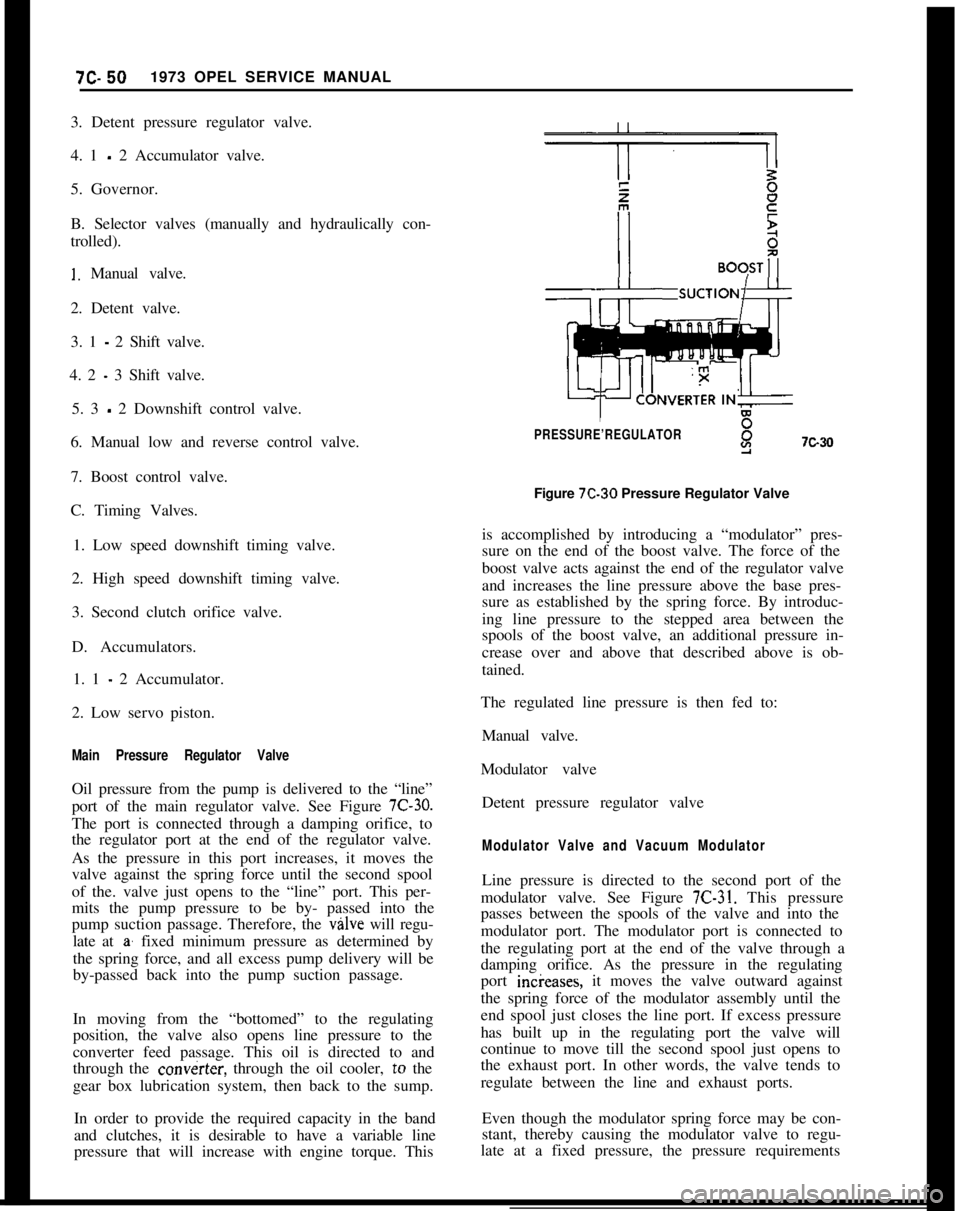
Main Pressure Regulator ValveOil pressure from the pump is delivered to the “line”
port of the main regulator valve. See Figure
7C-30.The port is connected through a damping orifice, to
the regulator port at the end of the regulator valve.
As the pressure in this port increases, it moves the
valve against the spring force until the second spool
of the. valve just opens to the “line” port. This per-
mits the pump pressure to be by- passed into the
pump suction passage. Therefore, the valve will regu-
late at
a’ fixed minimum pressure as determined by
the spring force, and all excess pump delivery will be
by-passed back into the pump suction passage.
In moving from the “bottomed” to the regulating
position, the valve also opens line pressure to the
converter feed passage. This oil is directed to and
through the
cow&x, through the oil cooler, to the
gear box lubrication system, then back to the sump.
In order to provide the required capacity in the band
and clutches, it is desirable to have a variable line
pressure that will increase with engine torque. This
PRESSURE’REGULATORY7c30Figure 7C-30 Pressure Regulator Valve
is accomplished by introducing a “modulator” pres-
sure on the end of the boost valve. The force of the
boost valve acts against the end of the regulator valve
and increases the line pressure above the base pres-
sure as established by the spring force. By introduc-
ing line pressure to the stepped area between the
spools of the boost valve, an additional pressure in-
crease over and above that described above is ob-
tained.
The regulated line pressure is then fed to:
Manual valve.
Modulator valve
Detent pressure regulator valve
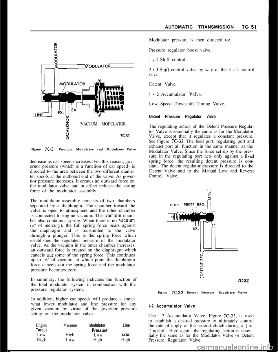
Modulator Valve and Vacuum ModulatorLine pressure is directed to the second port of the
modulator valve. See Figure
7C-31. This pressure
passes between the spools of the valve and into the
modulator port. The modulator port is connected to
the regulating port at the end of the valve through a
damping orifice. As the pressure in the regulating
port incieases, it moves the valve outward against
the spring force of the modulator assembly until the
end spool just closes the line port. If excess pressure
has built up in the regulating port the valve will
continue to move till the second spool just opens to
the exhaust port. In other words, the valve tends to
regulate between the line and exhaust ports.
Even though the modulator spring force may be con-
stant, thereby causing the modulator valve to regu-
late at a fixed pressure, the pressure requirements
Page 412 of 625
AUTOMATIC TRANSMISSION7c-51VACUUM MODULATOR7c31
Figure 7C-31 Vacuum Modulator and Modulator Valve
decrease as car speed increases. For this reason, gov-
ernor pressure (which is a function of car speed) is
directed to the area between the two different diame-
ter spools at the outboard end of the valve. As gover-
nor pressure increases, it creates an outward force on
the modulator valve and in effect reduces the spring
force of the modulator assembly.
The modulator assembly consists of two chambers
separated by a diaphragm. The chamber toward the
valve is open to atmosphere and the other chamber
is connected to engine vacuum. The vacwm cham-
ber also contains a spring. When there is no vacuum
(0” of mercury), the full spring force bears against
the diaphragm and is transmitted to the valve
through a plunger. This is the spring force which
establishes the regulated pressure of the modulator
valve. As the vacuum in the outer chamber increases,
an outward force is created on the diaphragm which
cancels out some of the spring force. This continues
up to
16” of vacuum, at which point the diaphragm
force cancels out the spring force and the modulator
pressure becomes zero.
In summary, the following indicates the function of
the total modulator system in combination with the
pressure regulator system.
In addition, higher car speeds will produce a some-
what lower modulator and line pressure for any
given vacuum by virtue of the governor pressure
acting on the modulator valve.
Engine
TorqueLow
High
VacuumHigh
Low
Modulator
PreSSWe
LowHigh
LineLOW
HighModulator pressure is then directed to:
Pressure regulator boost valve.
I - 2.Shift control.
2
- 3-Shift control valve by way of the 3 - 2 control
valve.Detent Valve.
I - 2 Accumulator Va!ve.
Low Speed Downshift Timing Valve.
Detent Pressure Regulator ValveThe regulating action of the Detent Pressure Regula-
tor Valve is essentially the same as for the Modulator
Valve, except that it regulates a constant pressure.
See Figure
7C-32. The feed port, regulating port and
exhaust port all function in the same manner as the
Modulator Valve. Since the force set up by the pres-
sure in the regulating port acts only against a
fixedspring force, the resulting detent pressure is con-
stant. The detent regulator pressure is directed to the
Detent Valve and to the Manual Low and Reverse
Control Valve.
DET. PRESS.,REG.
i7G3-2
Figure 7C-32 Detent Pressure Regulator Valve
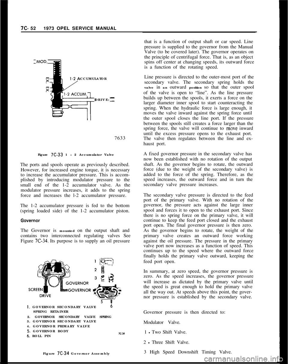
l-2 Accumulator ValveThe
I 2 Accumulator Valve, Figure 7C-33, is used
to establish a desired pressure to ultimately control
the rate of apply of the second clutch during a
I to
2 upshift. Here again, the regulating action is essen-
tially the same as for the Modulator Valve or Detent
Pressure Regulator Valve.
Page 413 of 625
7C- 521973 OPEL SERVICE MANUAL
CCUMULATOR
DRIVE:--7633
Figure 7C-33 1
- 2 Accumulator Valve
The ports and spools operate as previously described.
However, for increased engine torque, it is necessary
to increase the accumulator pressure. This is accom-
plished by introducing modulator pressure to the
small end of the 1-2 accumulator valve. As the
modulator pressure increases, it adds to the spring
force and increases the l-2 accumulator pressure.
The 1-2 accumulator pressure is fed to the bottom
(spring loaded side) of the 1-2 accumulator piston.
The Governor is mounted on the output shaft and
contains two interconnected regulating valves See
Figure
7C-34. Its purpose is to supply an oil pressure
5 8I. GOVERNOR SECONDARY VALVE6
SPRING RETAINER
2. GOVERNOR SECONDARY VALVE SPRING
3. GOVERNOR SECONDARY VALVE
4. GOVERNOR PRIMARY VALVE
5. GOVERNOR BODY6. ROLL PINIC~VFigure 7C-34 Governor Assemblythat is a function of output shaft or car speed. Line
pressure is supplied to the governor from the Manual
Valve (to be covered later). The governor operates on
the principle of centrifugal force. That is, as an object
spins off center at changing speeds, its outward force
is a function of the rotating speed.
Line pressure is directed to the outer-most port of the
secondary valve. The secondary spring holds the
valve in an outward position so that the outer spool
of the valve is open to “line”. As the line pressure
builds up between the spools, it exerts a force on the
larger diameter inner spool to start counteracting the
spring. When the hydraulic force is large enough, it
moves the valve inward against the spring force until
the outer spool closes the line port. If the pressure
between the spools still creates a force larger than the
spring force, the valve will continue to move inward
until the excess pressure opens to the exhaust port.
The valve then regulates between the line and ex-
haust port.
A fixed governor pressure in the secondary valve has
now been established with no rotation of the output
shaft. As the governor begins to rotate, the outward
force (due to the weight of the secondary valve) is
added to the force of the spring. Therefore, as the
speed increases, the outward force and in turn the
secondary valve pressure increases.
The secondary valve pressure is directed to the feed
port of the primary valve. With no rotation of the
governor, the pressure acts against the large inner
spool and forces it to open to the exhaust port. Since
there is no spring force on the primary valve, it will
continue to keep the feed port closed and the exhaust
port open. The final governor pressure is then zero.
As the governor begins to rotate, the weight of the
primary valve creates an outward force working
against the oil pressure. The pressure in the primary
valve port now increases as a function of speed. This
continues up to the speed where the outward force
finally holds the primary valve outward, keeping the
feed port open.
In summary, at zero speed, the governor pressure is
zero. As the speed increases, the governor pressure
will increase as dictated by the primary valve until
the speed is great enough to hold the primary valve
all the way out. At speeds above this point, the gover-
nor pressure is established by the secondary valve.
Governor pressure is then directed to:
Modulator Valve.
1 - Two Shift Valve.
2
- Three Shift Valve.
3 High Speed Downshift Timing Valve.
Page 414 of 625
AUTOMATIC TRANSMISSIONlC- 53
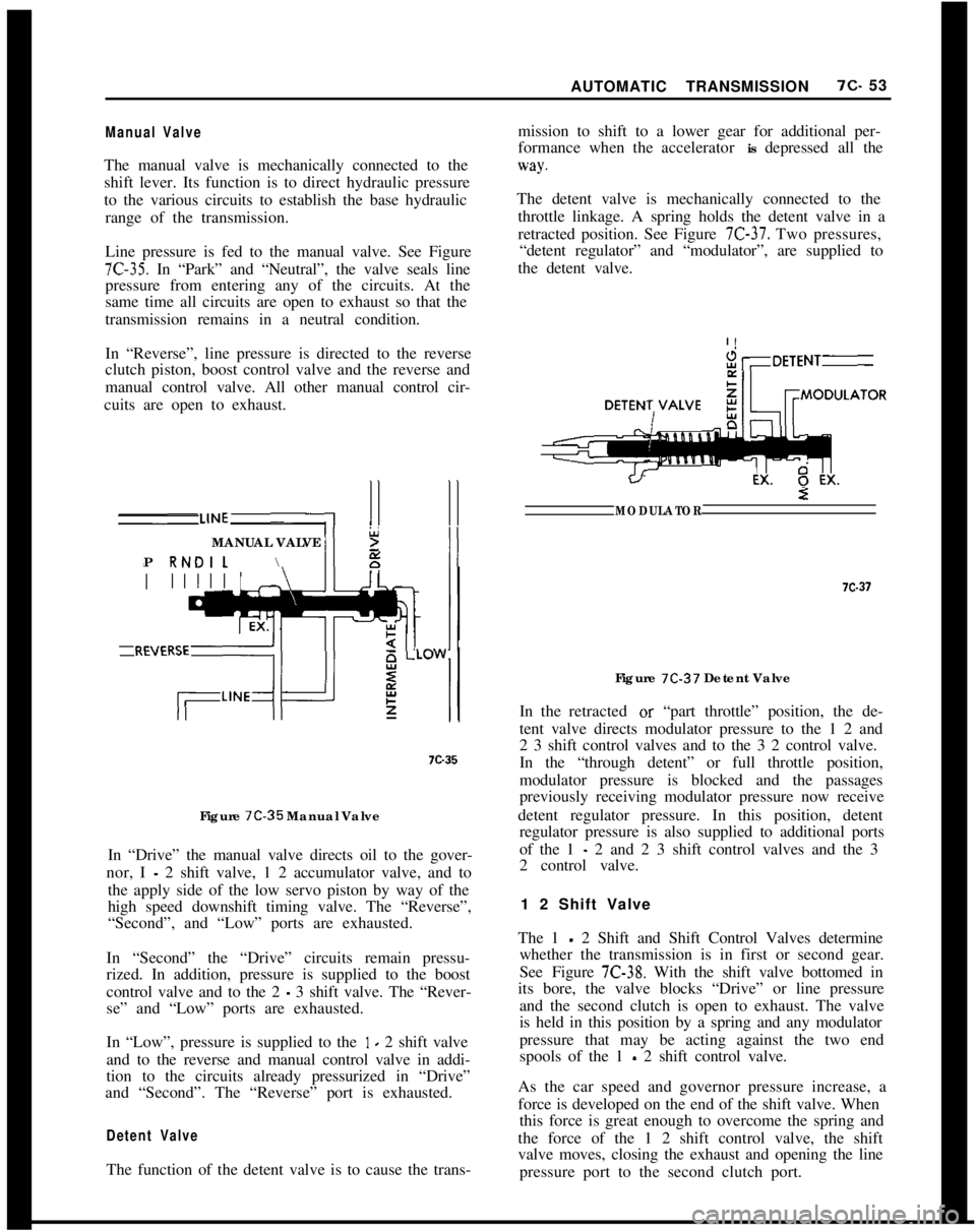
Manual ValveThe manual valve is mechanically connected to the
shift lever. Its function is to direct hydraulic pressure
to the various circuits to establish the base hydraulic
range of the transmission.
Line pressure is fed to the manual valve. See Figure
7C-35. In “Park” and “Neutral”, the valve seals line
pressure from entering any of the circuits. At the
same time all circuits are open to exhaust so that the
transmission remains in a neutral condition.
In “Reverse”, line pressure is directed to the reverse
clutch piston, boost control valve and the reverse and
manual control valve. All other manual control cir-
cuits are open to exhaust.
MANUAL VALVE
;i
\2
P RNDILII7D35
Figure
7C-35 Manual Valve
In “Drive” the manual valve directs oil to the gover-
nor, I
- 2 shift valve, 1 2 accumulator valve, and to
the apply side of the low servo piston by way of the
high speed downshift timing valve. The “Reverse”,
“Second”, and “Low” ports are exhausted.
In “Second” the “Drive” circuits remain pressu-
rized. In addition, pressure is supplied to the boost
control valve and to the 2
- 3 shift valve. The “Rever-
se” and “Low” ports are exhausted.
In “Low”, pressure is supplied to the
1 - 2 shift valve
and to the reverse and manual control valve in addi-
tion to the circuits already pressurized in “Drive”
and “Second”. The “Reverse” port is exhausted.
Detent ValveThe function of the detent valve is to cause the trans-mission to shift to a lower gear for additional per-
formance when the accelerator is depressed all the
way.The detent valve is mechanically connected to the
throttle linkage. A spring holds the detent valve in a
retracted position. See Figure
7C-37. Two pressures,
“detent regulator” and “modulator”, are supplied to
the detent valve.
iiiDETENTE2
MODULATORFigure
7C-37 Detent Valve
In the retracted or “part throttle” position, the de-
tent valve directs modulator pressure to the 1 2 and
2 3 shift control valves and to the 3 2 control valve.
In the “through detent” or full throttle position,
modulator pressure is blocked and the passages
previously receiving modulator pressure now receive
detent regulator pressure. In this position, detent
regulator pressure is also supplied to additional ports
of the 1
- 2 and 2 3 shift control valves and the 3
2 control valve.
1 2 Shift Valve
The 1
- 2 Shift and Shift Control Valves determine
whether the transmission is in first or second gear.
See Figure
7C-38. With the shift valve bottomed in
its bore, the valve blocks “Drive” or line pressure
and the second clutch is open to exhaust. The valve
is held in this position by a spring and any modulator
pressure that may be acting against the two end
spools of the 1
- 2 shift control valve.
As the car speed and governor pressure increase, a
force is developed on the end of the shift valve. When
this force is great enough to overcome the spring and
the force of the 1 2 shift control valve, the shift
valve moves, closing the exhaust and opening the line
pressure port to the second clutch port.
Page 415 of 625
7C- 541973 OPEL SERVICE MANUAL
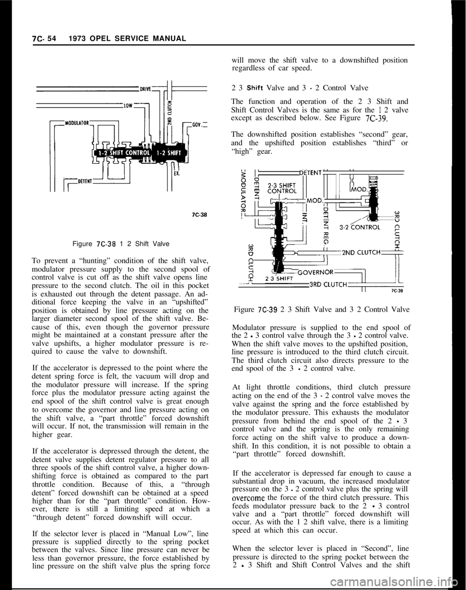
Figure 7C-38 1 2 Shift Valve
To prevent a “hunting” condition of the shift valve,
modulator pressure supply to the second spool of
control valve is cut off as the shift valve opens line
pressure to the second clutch. The oil in this pocket
is exhausted out through the detent passage. An ad-
ditional force keeping the valve in an “upshifted”
position is obtained by line pressure acting on the
larger diameter second spool of the shift valve. Be-
cause of this, even though the governor pressure
might be maintained at a constant pressure after the
valve upshifts, a higher modulator pressure is re-
quired to cause the valve to downshift.
If the accelerator is depressed to the point where the
detent spring force is felt, the vacuum will drop and
the modulator pressure will increase. If the spring
force plus the modulator pressure acting against the
end spool of the shift control valve is great enough
to overcome the governor and line pressure acting on
the shift valve, a “part throttle” forced downshift
will occur. If not, the transmission will remain in the
higher gear.
If the accelerator is depressed through the detent, the
detent valve supplies detent regulator pressure to all
three spools of the shift control valve, a higher down-
shifting force is obtained as compared to the part
throttle condition. Because of this, a “through
detent” forced downshift can be obtained at a speed
higher than for the “part throttle” condition. How-
ever, there is still a limiting speed at which a
“through detent” forced downshift will occur.
If the selector lever is placed in “Manual Low”, line
pressure is supplied directly to the spring pocket
between the valves. Since line pressure can never be
less than governor pressure, the force established by
line pressure on the shift valve plus the spring forcewill move the shift valve to a downshifted position
regardless of car speed.
2 3
,Shift Valve and 3 - 2 Control Valve
The function and operation of the 2 3 Shift and
Shift Control Valves is the same as for the
I 2 valve
except as described below. See Figure
7C-39.The downshifted position establishes “second” gear,
and the upshifted position establishes “third” or
“high” gear.
~ZND CLUTCH*
-I.Figure
7C-39 2 3 Shift Valve and 3 2 Control Valve
Modulator pressure is supplied to the end spool of
the 2
- 3 control valve through the 3 - 2 control valve.
When the shift valve moves to the upshifted position,
line pressure is introduced to the third clutch circuit.
The third clutch circuit also directs pressure to the
end spool of the 3
- 2 control valve.
At light throttle conditions, third clutch pressure
acting on the end of the 3
- 2 control valve moves the
valve against the spring and the force established by
the modulator pressure. This exhausts the modulator
pressure from behind the end spool of the 2
- 3
control valve and the spring is the only remaining
force acting on the shift valve to produce a down-
shift. In this condition, it is not possible to obtain a
“part throttle” forced downshift.
If the accelerator is depressed far enough to cause a
substantial drop in vacuum, the increased modulator
pressure on the 3
- 2 control valve plus the spring will
overc,ome the force of the third clutch pressure. This
feeds modulator pressure back to the 2
- 3 control
valve and a “part throttle” forced downshift will
occur. As with the 1 2 shift valve, there is a limiting
speed at which this can occur.
When the selector lever is placed in “Second”, line
pressure is directed to the spring pocket between the
2
- 3 Shift and Shift Control Valves and the shift
Page 416 of 625
AUTOMATIC TRANSMISSION7c- 55
valve will be held in downshifted, or second gear,
condition regardless of car speed.
Manual Low and Reverse Control Valve
As described in the text on “Mechanical Operation”,
the third clutch is applied in manual “Low” and in
“Reverse” to prevent a free wheeling condition. In
“Drive” range third gear, third clutch pressure is
also directed to the release side of the low servo (to
be covered later). This is the pressure which causes
the low band to release during a 2-3 upshift. How-
ever, in manual low, the band must remain applied
even though the third clutch is on.
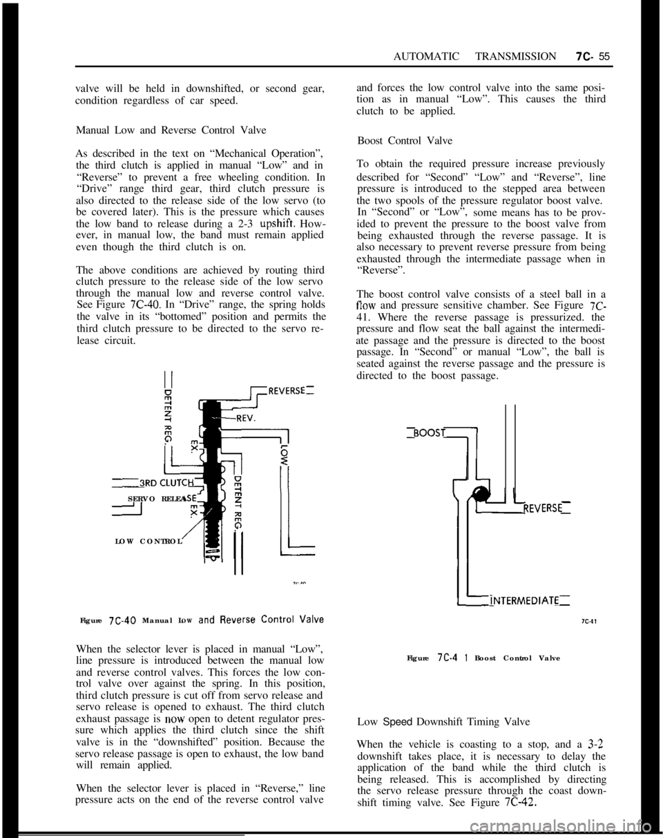
The above conditions are achieved by routing third
clutch pressure to the release side of the low servo
through the manual low and reverse control valve.
See Figure 7C-40. In “Drive” range, the spring holds
the valve in its “bottomed” position and permits the
third clutch pressure to be directed to the servo re-
lease circuit.
_~RDSERVO RELEA
ILOW CONTROL
Figure 7C-40 Manual LOW
and Ftever~e Control Valve
When the selector lever is placed in manual “Low”,
line pressure is introduced between the manual low
and reverse control valves. This forces the low con-
trol valve over against the spring. In this position,
third clutch pressure is cut off from servo release and
servo release is opened to exhaust. The third clutch
exhaust passage is now open to detent regulator pres-
sure which applies the third clutch since the shift
valve is in the “downshifted” position. Because the
servo release passage is open to exhaust, the low band
will remain applied.
When the selector lever is placed in “Reverse,” line
pressure acts on the end of the reverse control valveand forces the low control valve into the same posi-
tion as in manual “Low”. This causes the third
clutch to be applied.
Boost Control Valve
To obtain the required pressure increase previously
described for “Second” “Low” and “Reverse”, line
pressure is introduced to the stepped area between
the two spools of the pressure regulator boost valve.
In “Second” or “Low”,
some means has to be prov-
ided to prevent the pressure to the boost valve from
being exhausted through the reverse passage. It is
also necessary to prevent reverse pressure from being
exhausted through the intermediate passage when in
“Reverse”.
The boost control valve consists of a steel ball in a
flow and pressure sensitive chamber. See Figure 7C-41. Where the reverse passage is pressurized. the
pressure and flow seat the ball against the intermedi-
ate passage and the pressure is directed to the boost
passage. In “Second” or manual “Low”, the ball is
seated against the reverse passage and the pressure is
directed to the boost passage.
t-INTERMEDIATE
7c.4,
I I
REVERSE:Figure 7C-4
1 Boost Control Valve
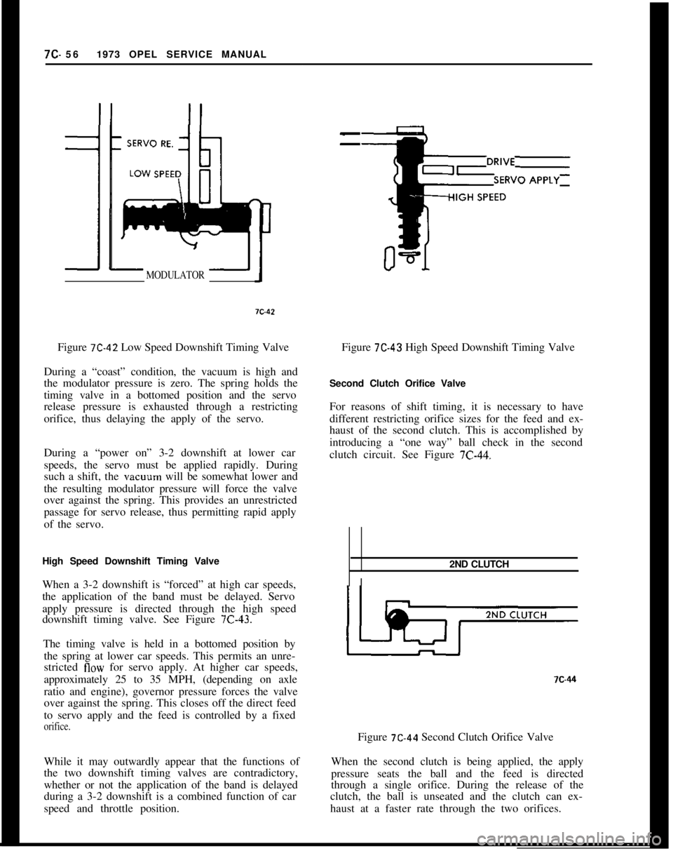
Low Speed Downshift Timing Valve
When the vehicle is coasting to a stop, and a
3-2downshift takes place, it is necessary to delay the
application of the band while the third clutch is
being released. This is accomplished by directing
the servo release pressure through the coast down-
shift timing valve. See Figure 7C-42.
Page 417 of 625
7C- 561973 OPEL SERVICE MANUALMODULATORFigure
7C-42 Low Speed Downshift Timing Valve
During a “coast” condition, the vacuum is high and
the modulator pressure is zero. The spring holds the
timing valve in a bottomed position and the servo
release pressure is exhausted through a restricting
orifice, thus delaying the apply of the servo.
During a “power on” 3-2 downshift at lower car
speeds, the servo must be applied rapidly. During
such a shift, the vacuum will be somewhat lower and
the resulting modulator pressure will force the valve
over against the spring. This provides an unrestricted
passage for servo release, thus permitting rapid apply
of the servo.
High Speed Downshift Timing Valve
When a 3-2 downshift is “forced” at high car speeds,
the application of the band must be delayed. Servo
apply pressure is directed through the high speed
downshift timing valve. See Figure
7C-43.The timing valve is held in a bottomed position by
the spring at lower car speeds. This permits an unre-
stricted
flow for servo apply. At higher car speeds,
approximately 25 to 35 MPH, (depending on axle
ratio and engine), governor pressure forces the valve
over against the spring. This closes off the direct feed
to servo apply and the feed is controlled by a fixed
orifice.While it may outwardly appear that the functions of
the two downshift timing valves are contradictory,
whether or not the application of the band is delayed
during a 3-2 downshift is a combined function of car
speed and throttle position.
--Figure
7C-43 High Speed Downshift Timing Valve
Second Clutch Orifice Valve
For reasons of shift timing, it is necessary to have
different restricting orifice sizes for the feed and ex-
haust of the second clutch. This is accomplished by
introducing a “one way” ball check in the second
clutch circuit. See Figure
7C-44.2ND CLUTCH
I?C-44
Figure
7C-44 Second Clutch Orifice Valve
When the second clutch is being applied, the apply
pressure seats the ball and the feed is directed
through a single orifice. During the release of the
clutch, the ball is unseated and the clutch can ex-
haust at a faster rate through the two orifices.
Page 418 of 625
AUTOMATIC TRANSMISSION7c-57
ACCUMULATORFigure
7C-46 1-2 Accumulator
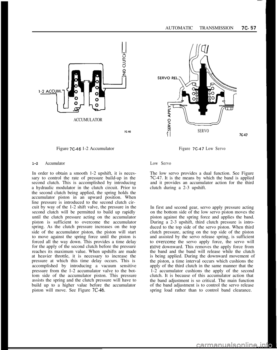
l-2 AccumulatorIn order to obtain a smooth 1-2 upshift, it is neces-
sary to control the rate of pressure build-up in the
second clutch. This is accomplished by introducing
a hydraulic modulator in the clutch circuit. Prior to
the second clutch being applied, the spring holds the
accumulator piston in an upward position. When
line pressure is introduced to the second clutch cir-
cuit by way of the 1-2 shift valve, the pressure in the
second clutch will be permitted to build up rapidly
until the clutch pressure acting on the accumulator
piston is sufficient to overcome the accumulator
spring. As the clutch pressure increases on the top
side of the accumulator piston, the piston will start
to move against the spring force until the piston is
forced all the way down. This provides a time delay
for the apply of the second clutch before the pressure
reaches its maximum value. When upshifts are made
at heavier throttle, it is necessary to increase the
pressure at which this time delay occurs. This is
accomplished by introducing a vacuum sensitive
pressure from the 1-2 accumulator valve to the bot-
tom side of the accumulator piston. This pressure
assists the spring and the clutch pressure will have to
build up to a higher value before the accumulator
piston will move. See Figure
7C-46.
SERVO7c-47
Figure 7C-47 Low Servo
Low ServoThe low servo provides a dual function. See Figure
7C-47. It is the means by which the band is applied
and it provides an accumulator action for the third
clutch during a 2-3 upshift.
In first and second gear, servo apply pressure acting
on the bottom side of the low servo piston moves the
piston against the spring force and applies the band.
During a 2-3 upshift, third clutch pressure is intro-
duced to the top side of the servo piston. When third
clutch pressure, acting on the top side of the piston
and assisted by the servo release spring, is sufficient
to overcome the servo apply force, the servo will
move downward. This removes the apply force from
the band and the band will release while the clutch
is being applied. During the downward movement of
the piston, a time interval occurs which cushions the
apply of the third clutch in the same manner that the
1-2 accumulator cushions the apply of the second
clutch. It is because of this accumulator action that
the band adjustment is so critical. The main function
of the band adjustment is to control the servo release
spring load rather than to control band clearance.
Page 419 of 625
7c. 581973 OPEL SERVICE MANUAL
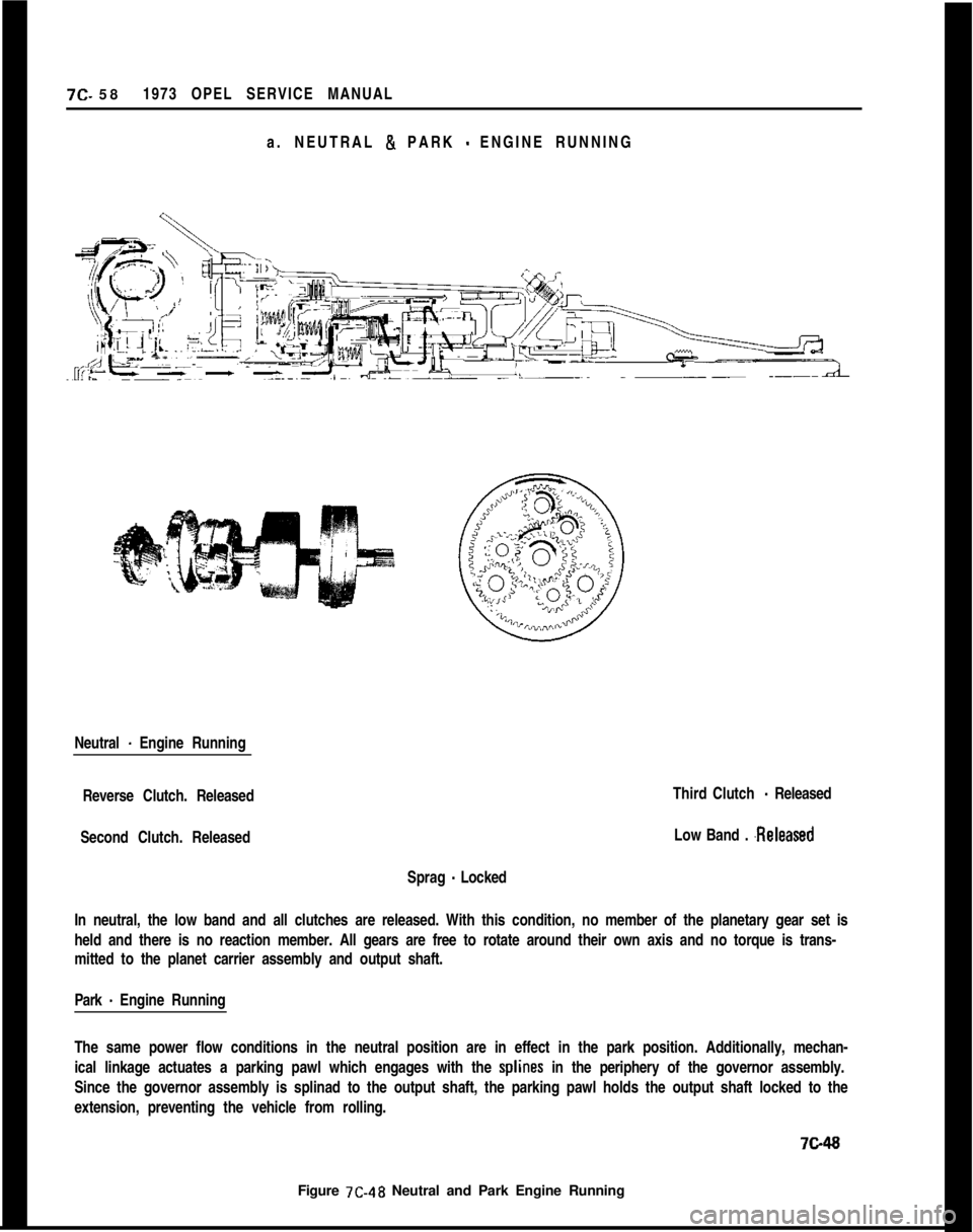
a. NEUTRAL & PARK
- ENGINE RUNNING
Neutral
- Engine Running
Reverse Clutch. Released
Second Clutch. Released
Sprag
- LockedThird Clutch
- Released
Low Band .
.ReleasedIn neutral, the low band and all clutches are released. With this condition, no member of the planetary gear set is
held and there is no reaction member. All gears are free to rotate around their own axis and no torque is trans-
mitted to the planet carrier assembly and output shaft.
Park
- Engine Running
The same power flow conditions in the neutral position are in effect in the park position. Additionally, mechan-
ical linkage actuates a parking pawl which engages with the
splines in the periphery of the governor assembly.
Since the governor assembly is splinad to the output shaft, the parking pawl holds the output shaft locked to the
extension, preventing the vehicle from rolling.7ci48
Figure 7C-48 Neutral and Park Engine Running
Page 420 of 625
AUTOMATIC TRANSMISSION7c- 59
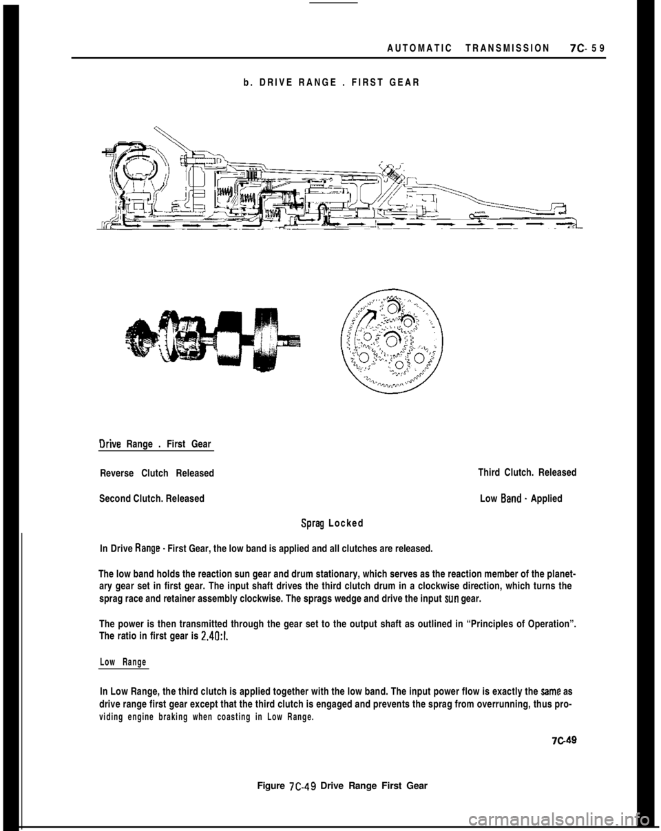
b. DRIVE RANGE . FIRST GEAROrive Range . First Gear
Reverse Clutch Released
Second Clutch. Released
Sprag Locked
In Drive Range. First Gear, the low band is applied and all clutches are released.
Figure 7C-49 Drive Range First GearThird Clutch. Released
Low Band. Applied
The low band holds the reaction sun gear and drum stationary, which serves as the reaction member of the planet-
ary gear set in first gear. The input shaft drives the third clutch drum in a clockwise direction, which turns the
sprag race and retainer assembly clockwise. The sprags wedge and drive the input
sun gear.
The power is then transmitted through the gear set to the output shaft as outlined in “Principles of Operation”.
The ratio in first gear is 2.4O:l.
Low RangeIn Low Range, the third clutch is applied together with the low band. The input power flow is exactly the
Same as
drive range first gear except that the third clutch is engaged and prevents the sprag from overrunning, thus pro-
viding engine braking when coasting in Low Range.
7c49