OPEL GT-R 1973 Service Manual
Manufacturer: OPEL, Model Year: 1973, Model line: GT-R, Model: OPEL GT-R 1973Pages: 625, PDF Size: 17.22 MB
Page 381 of 625

76.201973 OPEL SERVICE MANUAL
GEARSHIF
INTERMEDIATE SHAFT,
.SHIFT
FINGER1SELECTOR LEVER
JT “B’
78-7Figure’7B.7 Reverse Gearshift Blocker Adjustment
Figure
78-B3. Unhook tension spring of gearshift lever and, after
removal of retaining washer, push pivot pin out of
intermediate shift lever. See Figure
7B-10.1. Prior to installation, grease support and spherical
end of shift finger with protective grease.
2. Replace lever, pivot pin, retaining washer, and
tension spring. Reposition protective cap and bel-
lows and button cap from below. Replace console.
3. In
Figuie 7B-11, distance A - 8.07”.Figure 7B-10
7&l 1Figure 78.1 1
4. After installation, check as to whether pull ring
can be lifted up approximately
.04 to .08”, whereby
the stop sleeve must still rest against intermediate
shift lever. Otherwise, loosen threaded pin forBowden control wire attachment. See Figure 7B- 12.
Adjust distance B
- free travel - by lifting up pull
ring, and retighten threaded pin. See Figure 7B- 13.
REPLACING BOWDEN CONTROL WIRE IN
GEARSHIFT LEVER
1. Remove gearshift lever.
Page 382 of 625

MANUAL TRANSMISSION78.2178-12
Figure 78-l 2
Figure
78.132. Knock off gearshift lever button and loosen
threaded pin for Bowden control wire attachment.
See Figure 7B-12.
3. Drive spiral pin and clamping sleeve out of shift
finger tube and stop sleeve. See Figure 7B-14.
4. Remove shift finger and pull Bowden control wire,
together with thrust spring, out of gearshift lever.
5. Oil sliding surface of stop sleeve on shift finger
tube with clutch oil.
6. After installation of thrust spring, attach newBowden control wire first with clamping sleeve.
When doing this, the cutout of stop sleeve in installa-
tion position shows to the left. The spiral pins must
not protrude on either side.
7. Clamp tight Bowden control wire with threaded
pin. Prior to tightening, pull ring must rest on gear-
shift lever tube and clamping block on pull ring.SPIRAL PINS7B-14
Figure 71-14
8. Heat up new gearshift lever knob in boiling water
to 176 degrees F. and push it onto lever tube. Ob-
serve distance A
- .3”, see Figure 7B-15. The gear-
shift lever tube end is provided with transverse
grooves for which reason the old button can no
longer be used.7515
Figure
78-l 5
9. Attach shift finger with spiral pin and install gear-
shift lever.
REPLACING GEARSHIFT LEVER BELLOWS
1. Remove gearshift lever.
2. Knock off gearshift lever button and pull off bel-
lows over pull ring.
Page 383 of 625
78.221973 OPEL SERVICE MANUAL
3. Install new bellows. Adhere to distance A
- 8.07”.
See Figure 7B-I 1.
4. Heat up new gearshift lever knob in boiling water
to 176 degrees F. and push it onto gearshift lever
tube. Adhere to distance A .3”, see Figure
7B-15.The gearshift lever tube end is provided with trans-
verse grooves for which reason the old button cannot
be reused. Install gearshift lever.
REPLACING RUBBER DAMPENING PARTS IN
GEARSHIFT LEVER1. Remove gearshift lever.
2. Knock off gearshift lever button and loosen
threaded pin for Bowden control wire attachment.
3. Remove lower snap ring from gearshift lever tube
and pull tube off shift finger.
4. Take off and replace rubber dampening parts.
5. After installation of tube, tighten Bowden control
wire with threaded pin. Prior to tightening, pull ring
must rest on gearshift lever tube and clamping block
on pull ring. See Figure
7B-15.6. Heat up new gearshift lever knob in boiling water
to 176 degrees F. and push it onto gearshift lever
tube. Adhere to distance A
- .3”, see Figure 7B-15.The gearshift lever tube end is provided with trans-
verse grooves for which reason the old button cannot
be reused.
7. Install gearshift lever.
MAJOR REPAIR
TRANSMISSION REMOVAL1. Remove air cleaner. Remove throttle rod from
carburetor and rear support and disconnect battery.
2. Remove screws from fan shroud.
3. Remove gearshift lever (refer to paragraph on ser-
vicing gearshift lever).
4. Support car with frame or wheel stands in the
front or frame stands in the rear.
5. Loosen front exhaust pipe to manifold flange.
6. Remove clutch cable from fork by pushing fork to
disengage the clutch and unsnap cable from slot.
7. Disconnect both wires from backup lamp switch.8. Disconnect speedometer cable from transmission
case extension housing.
9. Unhook parking brake cable return spring and
remove cable adjusting nut, equalizer, and spacer.
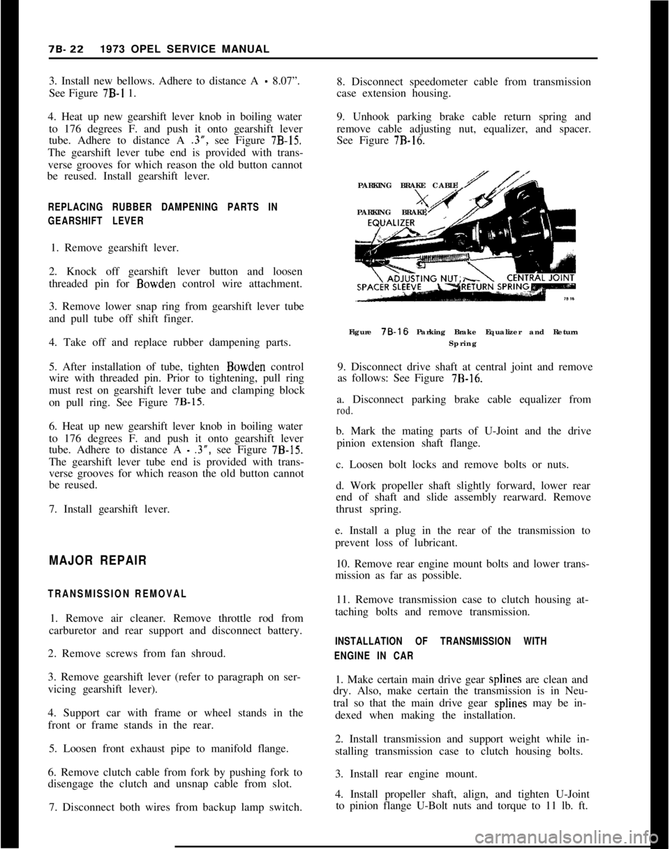
See Figure
7B-16.PARKING BRAKE CABLE
PARKING BRAKE
Figure 78-16 Parking Brake Equalizer and Return
Spring
9. Disconnect drive shaft at central joint and remove
as follows: See Figure
7B-16.a. Disconnect parking brake cable equalizer from
rod.b. Mark the mating parts of U-Joint and the drive
pinion extension shaft flange.
c. Loosen bolt locks and remove bolts or nuts.
d. Work propeller shaft slightly forward, lower rear
end of shaft and slide assembly rearward. Remove
thrust spring.
e. Install a plug in the rear of the transmission to
prevent loss of lubricant.
10. Remove rear engine mount bolts and lower trans-
mission as far as possible.
11. Remove transmission case to clutch housing at-
taching bolts and remove transmission.
INSTALLATION OF TRANSMISSION WITH
ENGINE IN CAR1. Make certain main drive gear splines are clean and
dry. Also, make certain the transmission is in Neu-
tral so that the main drive gear splines may be in-
dexed when making the installation.
2. Install transmission and support weight while in-
stalling transmission case to clutch housing bolts.
3. Install rear engine mount.
4. Install propeller shaft, align, and tighten U-Joint
to pinion flange U-Bolt nuts and torque to 11 lb. ft.
Page 384 of 625
MANUAL TRANSMISSION70.235. Attach clutch cable.
6. Perform clutch lash adjustment. See Clutch, Sec-
tions A and B for adjustment procedure.
7. After overhaul of transmission, refill with
2- l/2pints of SAE 80 or SO-90 multi-purpose gear Iubri-
cant.
REMOVING AND INSTALLING SPEED0 DRIVEN
GEAR
(WITH TRANSMISSION REMOVED)
Removing Speedo Driven Gear Assembly1. Use wrench to unscrew speed0 angular drive hold-
ing nut and remove speedo angular drive.
2. With Special Tool J-22926 and Slide Hammer
J-7004- 1, remove speedo driven gear lock pin which
retains speed0 driven gear assembly in transmission
case extension housing.
3. Using Special Tool J-22929 and Slide Hammer
J-7004- 1, remove speed0 driven gear assembly. Tool
J-2292? screws onto the speedo driven gear guide
making it possible to remove the guide and assembly
without damage to the transmission case extension
housing.
Installation of Speedo Driven Gear Assembly1. Using Special Tool J-22929 install speedo driven
gear assembly into transmission case extension hous-
ing. It may be necessary to tap lightly on tool
J-22929 when installing assembly. Be sure speedo
driven gear lock pin hole on guide lines up with hole
in transmission case extension housing. Also, rotate
mainshaft at output end when inserting speed0
driven gear assembly to insure that driven gear
meshes properly with speed0 drive gear on main-
shaft.2. Install speed0 driven gear lock pin into transmis-
sion case extension housing by tapping pin lightly.
3. Install speed0 angular drive by tightening speedo
angular drive to holding nut.
REPLACING BUSHING IN SELECTOR LEVER
(TRANSMISSION AND GEARSHIFT LINKAGE
REMOVED)
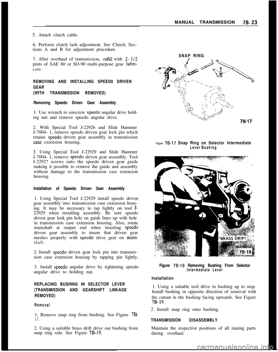
Removal1. Remove snap ring from bushing. See Figure 7B-
17.2. Using a suitable brass drift drive out bushing from
snap ring side. See Figure
7B-19.SNAP RING
Figure 78.17 Snap Ring on Selector Intermediate
Lever Bushing
Figure 78.19 Removing Bushing From SelectorIntermediate Lever
Installation1. Using a suitable tool drive in bushing up to stop.
Install bushing in opposite direction of removal with
the cutout in the bushing facing upwards. See Figure7B-
19.2. Install snap ring onto bushing.
TRANSMISSION DISASSEMBLYMaintain the respective positions of all mating parts
during overhaul.
Page 385 of 625
78.241973 OPEL SERVICE MANUAL
Removing Shifter Shaft
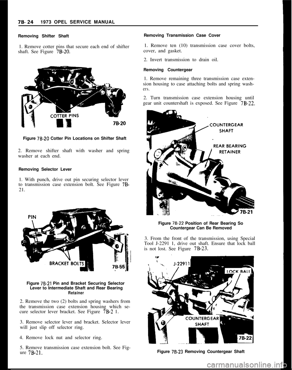
1. Remove cotter pins that secure each end of shifter
shaft. See Figure
7B-20.7&20
Figure 78.20 Cotter Pin Locations on Shifter Shaft
2. Remove shifter shaft with washer and spring
washer at each end.
Removing Selector Lever
1. With punch, drive out pin securing selector lever
to transmission case extension bolt. See Figure 7B-
21.
Figure
78-21 Pin and Bracket Securing Selector
Lever to Intermediate Shaft and Rear Bearing
Retainer2. Remove the two (2) bolts and spring washers from
the transmission case extension housing which se-
cure selector lever bracket. See Figure 7B-2 1.
3. Remove selector lever and bracket. Selector lever
will just slip off selector ring.
4. Remove lock nut and selector ring.
5. Remove transmission case extension bolt. See Fig-
ure 7B-21.Removing Transmission Case Cover
1. Remove ten (10) transmission case cover bolts,
cover, and gasket.
2. Invert transmission to drain oil.
Removing Countergear
1. Remove remaining three transmission case exten-
sion housing to case attaching bolts and spring wash-
ers.2. Turn transmission case extension housing until
gear unit countershaft is exposed. See Figure 7B-22.
Figure
78-22 Position of Rear Bearing So
Countergear Can Be Removed
3. From the front of the transmission, using Special
Tool J-2291 1, drive out shaft. Ensure that lock ball
is not lost. See Figure 7B-23.
Figure
78-23 Removing Countergear Shaft
Page 386 of 625

MANUAL TRANSMISSION78.254. With Special Tool J-2291 1 inserted, take counter-
shaft gear unit out of transmission case. Remove
both thrust washers.
Removing Selector Shaft and Intermediate Levers
1. Drive out reverse intermediate lever bedding bolt
and remove reverie speed shifter intermediate lever.
See Figure 7B-24.*EVE&E
JNTERME!Figure
78-24 Driving Out Reverse Intermediate LeverPin2. To remove all pins, use a
l/8 inch pin punch. Turn
the selector shaft so that lock pins are in vertical
position. First, drive lock pins out of third and fourth
speed intermediate lever and then out of first and
second speed intermediate lever. See Figure 7B-25.3. Push selector shaft out of case and remove inter-
mediate levers.
4. With screwdriver, pry out selector shaft oil seals
on transmission case.
Removing First and Second Gear Shifter Shaft,
Yoke, and Cam1. Pull out both lock ball plugs using Tool J- 21715
with Slide Hammer J-7004-1. Remove thrust
springs.
2. With transmission in first gear, drive lock pins out
of shifter yokes and shifter shaft cam. See Figure7B-26.
Figure
78-26 Position of Lock Pins for Shifter Forks
and Selector Dogs
3. Turn extension housing until shifter shaft is ex-
posed. From the rear of transmission, drive out first
and second speed shifter shaft. Use suitable brass
drift. See Figure 7B-27.
Figure
78-25 Removing Lock Pins from Selector Shaft
Figure 78.27 Removing Shifter Shafts
Page 387 of 625
78.261973 OPEL SERVICE MANUAL
4. Remove both first and second speed shifter yoke
and shifter shaft cam.
Removing Main Drive Gear and Mainshaft
Assembly
1. From front of transmission, pull main drive gear
and needle bearing out of transmission. (May be
necessary to rock main drive gear.)
2. From rear of transmission, pull mainshaft assem-
bly and transmission case extension housing out of
transmission. Gear shifter sleeve will be pulled off
gear shifter sleeve carrier by the third and fourth
speed shifter yoke. Remove sleeve from yoke and
keep sleeve with mainshaft assembly. (Make sure
third and fourth speed shoes are not lost.)
Removing Third and Fourth Gear Shifter Shaft.
1. With main shaft assembly out of transmission
case, drive third and fourth gear shifter shaft out
through hole in front of case with brass drift from
rear of transmission through mainshaft assembly
hole in case.
2. Remove third and fourth speed yoke.
Removing Reverse Gear Shifter Shaft and Reverse
Idler Gear
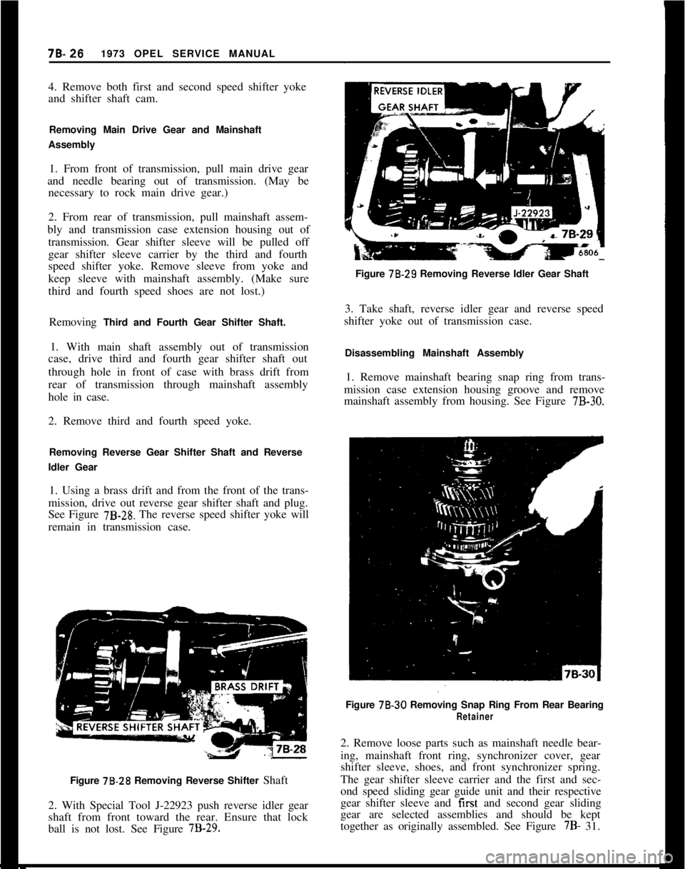
1. Using a brass drift and from the front of the trans-
mission, drive out reverse gear shifter shaft and plug.
See Figure
7B-28. The reverse speed shifter yoke will
remain in transmission case.
Figure 78.28 Removing Reverse Shifter Shaft
2. With Special Tool J-22923 push reverse idler gear
shaft from front toward the rear. Ensure that lock
ball is not lost. See Figure
7B-29.Figure 78.29 Removing Reverse Idler Gear Shaft
3. Take shaft, reverse idler gear and reverse speed
shifter yoke out of transmission case.
Disassembling Mainshaft Assembly
1. Remove mainshaft bearing snap ring from trans-
mission case extension housing groove and remove
mainshaft assembly from housing. See Figure
7B-30.Figure 78-30 Removing Snap Ring From Rear Bearing
Retainer2. Remove loose parts such as mainshaft needle bear-
ing, mainshaft front ring, synchronizer cover, gear
shifter sleeve, shoes, and front synchronizer spring.
The gear shifter sleeve carrier and the first and sec-
ond speed sliding gear guide unit and their respective
gear shifter sleeve and first and second gear sliding
gear are selected assemblies and should be kept
together as originally assembled. See Figure 7B- 31.
Page 388 of 625
MANUAL TRANSMISSION78-27
SYNCHRONIZER
SPAZER RINGf&31Figure 78.31
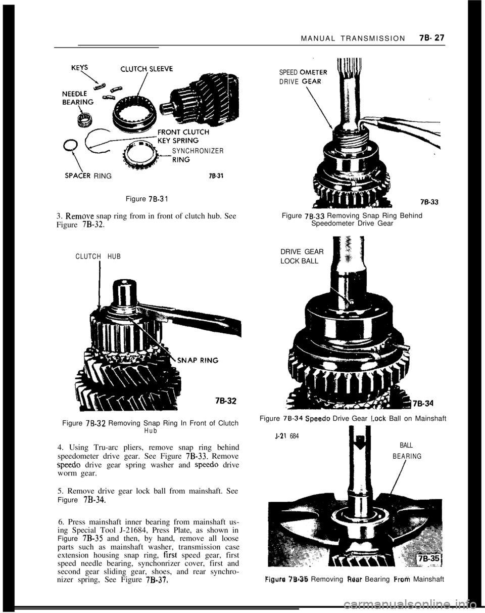
3. Remow snap ring from in front of clutch hub. See
Figure
7B-32.
SPEED
DRIVEFigure 78.33 Removing Snap Ring Behind
Speedometer Drive Gear
CLUTCH HUBFigure
7%.32 Removing Snap Ring In Front of ClutchHub4. Using Tru-arc pliers, remove snap ring behind
speedometer drive gear. See Figure
7B-33. Removespeedo drive gear spring washer and speed0 drive
worm gear.
5. Remove drive gear lock ball from mainshaft. See
Figure
7B-34.6. Press mainshaft inner bearing from mainshaft us-
ing Special Tool J-21684, Press Plate, as shown in
Figure 7B-35 and then, by hand, remove all loose
parts such as mainshaft washer, transmission case
extension housing snap ring, first speed gear, first
speed needle bearing, synchonrizer cover, first and
second gear sliding gear, shoes, and rear synchro-
nizer spring, See Figure
7B.370DRIVE GEAR
LOCK BALL
Figure 78.34
Speedo Drive Gear I.ock Ball on Mainshaft
l-21 684
BALL
BEARING
/
Figure 78.36 Removing Rest Bearing Frotii Mainshaft
Page 389 of 625

iB- 281973 OPEL SERVICE MANUAL
1 ST SPEED
GINEEDLE BEARING-/CLUTCH
SLEEc?iE,-.
SNAP RING_.. ..~~ ~-KEY SPRING,a-37Figure 70-37Figure 7B-39 Pressing Off Small Clutch Hub
7. With Special Tool J-21684, Press Plate, located
below third speed gear, press out gear shifter sleeve
carrier. See Figure
7B-38.2. Install third speed synchronizer cover onto third
speed gear cone.
J-21604
\
2ND SPEED
GE,ARFigure 78.38 Pressing Off Large Clutch Hub and
Needle Bearing Inner Sleeve8. With Special Tool J-21684, Press Plate, located
below second speed gear, press out gear shifter sleevecarrier. See Figure
7B-39.
TRANSMISSION REASSEMBLY
A. Assembling Mainshaft1. From front of the mainshaft install third speedf;cz&mto mainshaft. Gear must turn freely on main-3. Install rear synchronizer spring into rear side of
gear shifter sleeve carrier so that hooked spring end
rests in one of the slots.
4. Using Press Plate J-21684, press gear shifter sleeve
carrier onto mainshaft so that original tooth contact
is obtained. The rear side of gear shifter sleeve carrier
with installed spring should be toward third speed
gear. This rear side of carrier is recessed more than
front side to allow carrier to be pressed almost flush
with synchronizer cover. See Figure
7B-40.3rd
8 4th
Figure 78.40 Securing Third and Fourth Speed Clutch
Hub on Mainshaft With Snap Ring
Page 390 of 625

MANUAL TRANSMISSION78.29
5. Using external snap ring pliers, secure gear shifter
sleeve carrier on mainshaft with snap ring. See Fig-
ure
7B-40.6. From rear of mainshaft, slide second speed gear
onto mainshaft. Gear must turn freely on mainshaft.
See Figure
7B-41.
2ND SPEED
GEAR CONE\
3RD SPEED
GEAR
MAIN
L; SYNCHRONIZER
VER2ND SPEED
GEAR
7B.41Figure
7B-41 Second Speed Gear and Synchronizer
Ring Installed
7. Place second speed synchronizer cover onto sec-
ond speed gear cone. See Figure
7B-41.
8. Install both synchronizer springs into first and
second speed sliding gear guide unit so that hooks of
both springs rest in the same guide unit shoe slot and
the other spring ends are positioned opposite to each
other. See Figure 78-42.
9. Press first and second speed sliding gear guide unit
onto mainshaft so that the original tooth contact is
obtained.
10. Using Tool J-22913, press first speed gear needle
bearing inner sleeve onto mainshaft.
11. Using Tool J-22913, install tirst and second speed
shoes (long style) and install first and second gear
sliding gear (forked groove to rear) onto first and
second speed sliding gear guide unit.
12. Slide first speed gear needle bearing, synchro-
nizer cover, first speed gear, mainshaft washer
(chamfer toward rear), and mainshaft bearing snap
ring onto mainshaft.
13. Press on mainshaft inner bearing using Tool
J-22913. See Figure
7B-43.GUIDE UNIT
SYNCHRONWER SPRING
Figure 78.42 Both Clutch Key Springs Installed
RI
d-J-22913 MAINSHAFT
ASSEMBLY TOOL
---- .
~.
7B.uFigure 78.43 Pressing on Rear Bearing Using Tool
J-22913
14. Insert lock ball in place in mainshaft and place
speedo drive worm gear and speed0 drive gear spring
washer on mainshaft. Secure with speedo drive gear
snap ring.
15. Place mainshaft assembly into transmission case
extension housing up to its stop. Secure with main-
shaft bearing snap ring. See Figure 7%44.