PONTIAC FIERO 1988 Service Repair Manual
Manufacturer: PONTIAC, Model Year: 1988, Model line: FIERO, Model: PONTIAC FIERO 1988Pages: 1825, PDF Size: 99.44 MB
Page 151 of 1825
3A-4 WHEEL ALIGNMENT
AXLE HOUSING ALIGNMENT 2. If a tram is used for checking toe out, it will still
be necessary to perform Steps
1 and 2 in order to If rear tire wear indicates that the axle housing
check camber.
may be bent, the alignment can be checked as follows:
The necessary straightening operations may be
1. Back the car squarely onto an alignment performed using frame straightening equipment
machine, ~h~ actual toe-out will be read on the without removing the axle housing from the car. This
scale as toe-in. However, if the toe-out is checked procedure will allow checks during the straightening
with a tram gage, disregard this notice. operation
to determine when the housing is within the
prescribed limits.
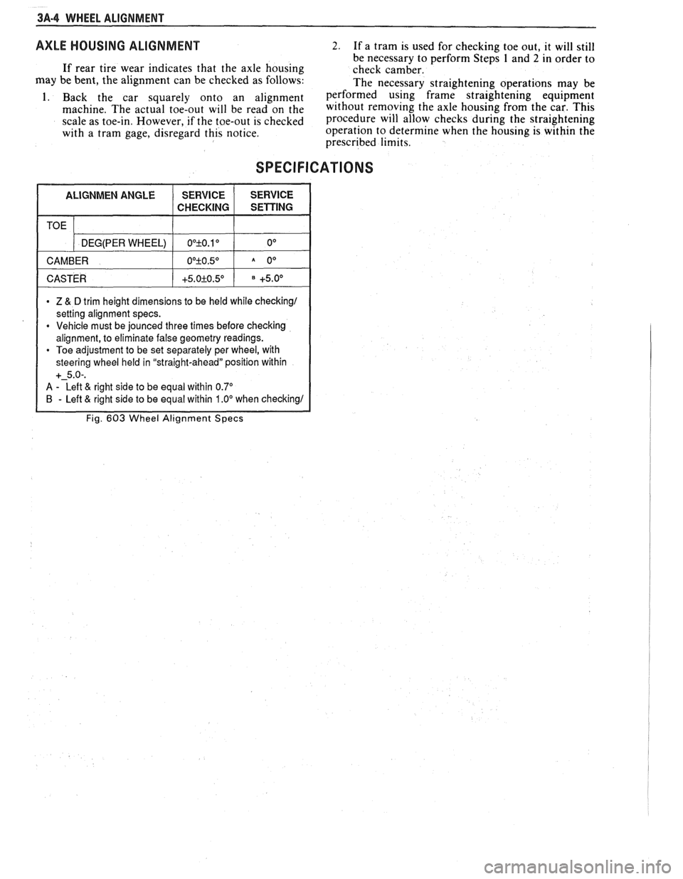
SPECIFICATIONS
1 CASTER 1 +5.0+0.5O 1 +5.0° 1
TOE
* Z & D trim height dimensions to be held while checking1
setting alignment specs.
* Vehicle must be jounced three times before checking
alignment, to eliminate false geometry readings.
Toe adjustment to be set separately per wheel, with
steering wheel held in "straight-ahead" position within
+-5.0-.
A - Left & right side to be equal within 0.7"
B - Left & right side to be equal within 1 .OO when checking1
Fig. 603 Wheel Alignment Specs
DEG(PER WHEEL)
CAMBER OO+O.10 0°
O0+O.5O A 0°
Page 152 of 1825
STEERING WHEELS AND COLUMNS 385.1
SECTION 3B5
STEER NG WHEELS AND COLUMNS
NOTICE: All steering wheel and column fasteners are important attaching parts in that they could affect
the performance of vital parts and systems, and/or could result in major repair expense. They
must be replaced
with one of the same part number or with an equivalent part if
replacement becomes necessary. Do not use a
replacement part of lesser quality or substitute design. 'Torque values must be used as specified during reassembly
to assure proper retention of all parts. There is to be no welding as
it may result in extensive damage and weakening
of the metal.
For prevailing torque
nut(s) and bolts(s), refer to the "Reuse of Prevailing Torque Nut(<) and Bolt(s) " chart
in Section OA.
CONTENTS
..................... ................................................................... GENERAL DESCRIPTION .. 3B5-1 ............................................. ........................ MAINTENANCE AND ADJUSTMENTS .. 3B5-1 ON-CAR SERVICE ........................................................................................................ 3B5-2
Steering Column ............................................................................................................ 3B5-2 ......................................................................................................... Intermediateshaft 3B5-3
Park Lock Cable .................................................................... 3B54 ......................................................................................... Checking For Accident Damage 3B5-5 ............................................................................ Unit Repair Intermediate Shaft Assembly 3B5-6
..................................................................................... Standard Column @lanual Trans) 3B5-7 ......................................................... ....................... Standard Column (Auto Trans) .. 3B5-13 Tilt Column (Manual Trans) ............................................................................................. 3B5-19
Tilt Column (Auto Trans). ................................................................................................ 3B5-27
................ .................... TORQUE SPECIFICATIONS .. .. 3B5-35
SPECIAL TOOLS .......................................................................................................... 3B5-35
GENERAL DESCRIPTION
STEERING COLUMN
The function locking energy absorbing steering
column includes three important features in addition
to the steering function:
1. 'The column is energy absorbing, designed to
compress in a front-end collision to minimize the
possibility of an injury to the driver of the car.
2. The ignition switch and lock are mounted
conveniently on this column.
3. With the column mounted lock, the ignition and
steering operations can be locked to inhibit theft
of the car.
The turn signal lever provides for control of
headlight beams, windshield washer and wipers.
The column may be easily
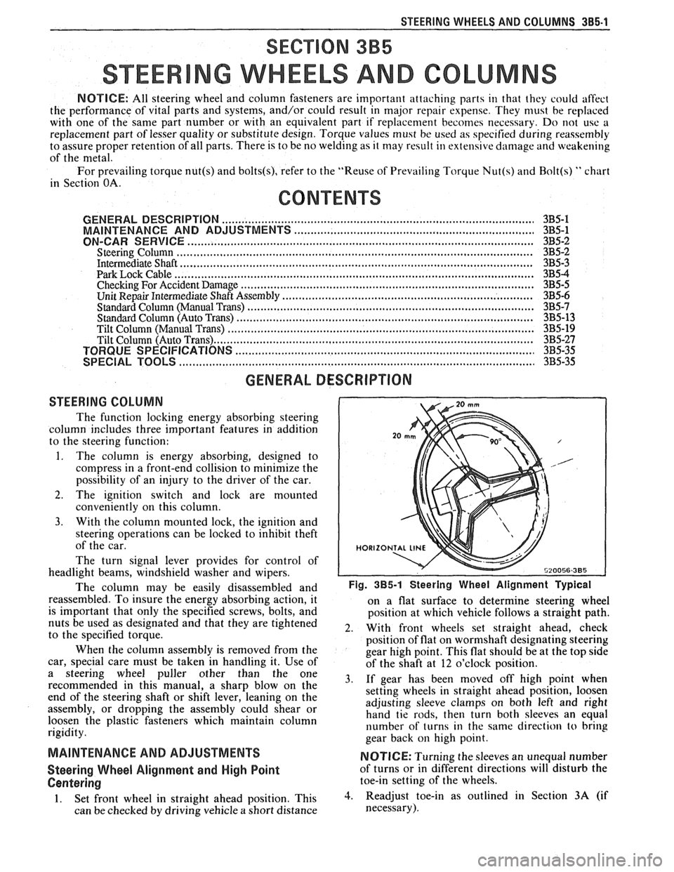
disassembled and Fig. 385-1 Steering Wheel Alignment ~ypical
reassembled. To insure the energy absorbing action, it
on a flat surface to determine steering wheel
is important that only the specified screws, bolts, and
position at which vehicle follows a straight path.
nuts be used as designated and that they are tightened
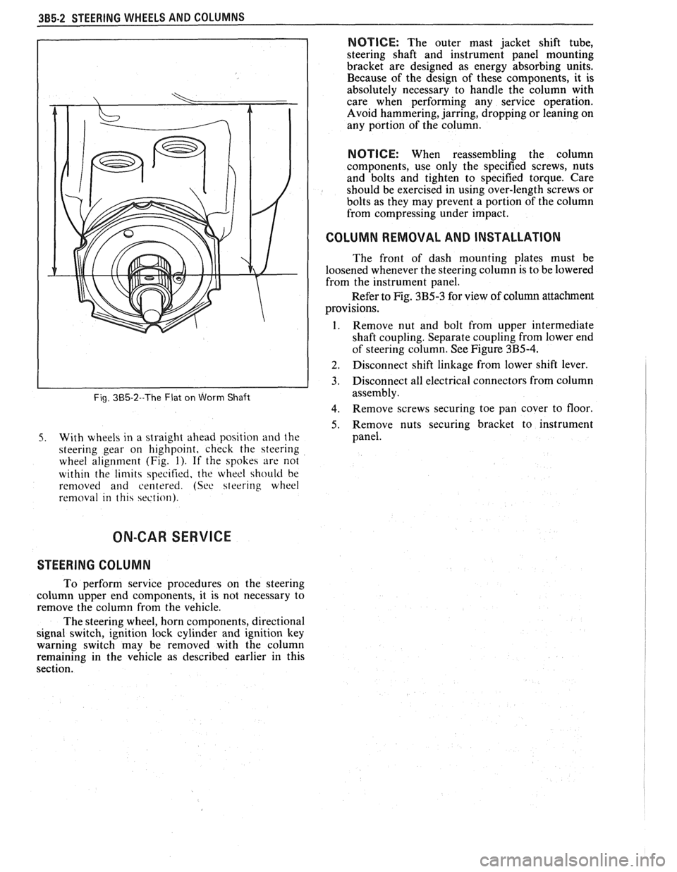
2. With front wheels set straight ahead, check to the specified torque.
position of flat on wormshaft designating steering
When the column assembly is removed from the
gear high point. This flat should be at the top side
car, special care must be taken in handling it. Use of
of the shaft at 12 o'clock position.
a steering puller other than the One 3, if gear has been moved off high when recommended in this manual, a sharp blow on the
setting wheels in straight ahead position, loosen
end of the steering shaft or shift lever, leaning on the
assembly, or dropping the assembly could shear or adjusting
sleeve clamps on both left and right
hand tie rods, then turn both sleeves an equal
loosen the plastic fasteners which maintain column
rigidity. number
of turns in the same direction
to bring
gear back
on high point.
MAINTENANCE AND ADJUSTMENTS NOTICE: Turning the sleeves an unequal number
Steering Wheel Alignment and High Point of turns or in different directions will disturb the
Centering toe-in setting of the wheels.
1. Set front wheel in straight ahead position, This 3. Readjust toe-in as outlined in Section 3A (if
can be checked by driving vehicle
a short distance necessary).
Page 153 of 1825
385-2 STEERING WHEELS AND COLUMNS
Fig. 385-2--The Flat on Worm Shaft
5. With wheels in a straight ahead position and the
steering gear on highpoint, check the steering
wheel alignment (Fig.
1). If the spokes are not
within the
limits specified, the wheel should be
removed
and centered. (See steering wheel
removal in this section).
NOTICE: The outer mast jacket shift tube,
steering shaft and instrument panel mounting
bracket are designed as energy absorbing units.
Because of the design of these components, it is
absolutely necessary to handle the column with
care when performing any service operation.
Avoid hammering, jarring, dropping or leaning on
any portion of the column.
NOTICE: When reassembling the column
components, use only the specified screws, nuts
and bolts and tighten to specified torque. Care
should be exercised in using over-length screws or
bolts as they may prevent a portion of the column
from compressing under impact.
I COLUMN REMOVAL AND INSTALLATION
The front of dash mounting plates must be
loosened whenever the steering column is to be lowered
from the instrument panel.
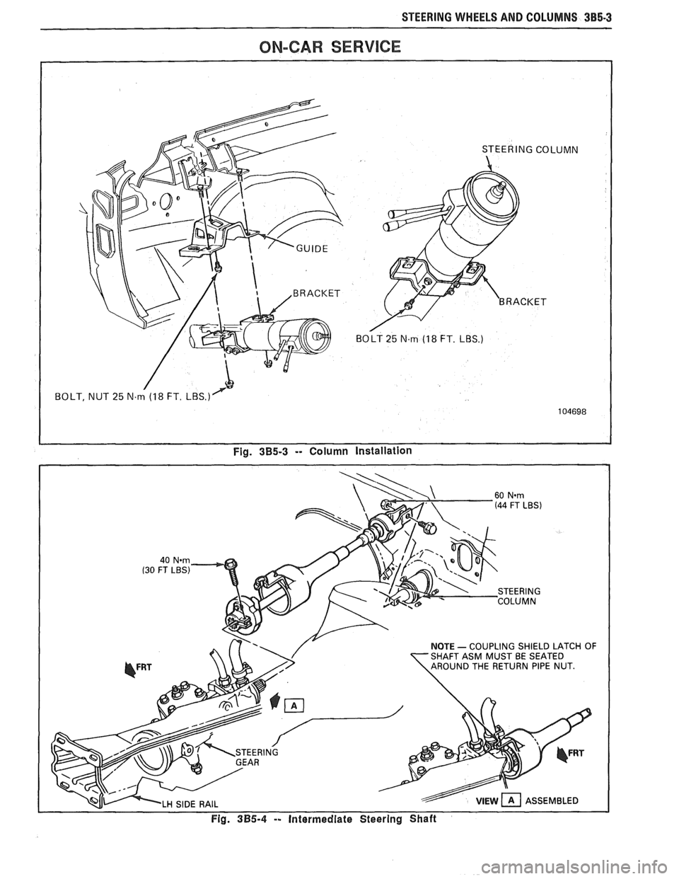
Refer to Fig. 3B5-3 for view of column attachment
provisions.
1. Remove nut and bolt from upper intermediate
shaft coupling. Separate coupling from lower end
of steering column. See Figure
3B5-4.
] 2. Disconnect shift linkage from lower shift lever.
3. Disconnect all electrical connectors from column
assembly.
4. Remove screws securing toe pan cover to floor
5. Remove nuts securing bracket to instrument
panel.
ON-CAR SERVICE
STEERING COLUMN
To perform service procedures on the steering
column upper end components, it is not necessary to
remove the column from the vehicle.
The steering wheel, horn components, directional
signal switch, ignition lock cylinder and ignition key
warning switch may be removed with the column
remaining in the vehicle as described earlier in this
section.
Page 154 of 1825
STEERING WHEELS AND COLUMNS 385-3
ON-CAR SERVICE
NOTE - COUPLING SHIELD LATCH OF
Fig. 3B5-4 -- Intermediate Steering Shaft
Page 155 of 1825
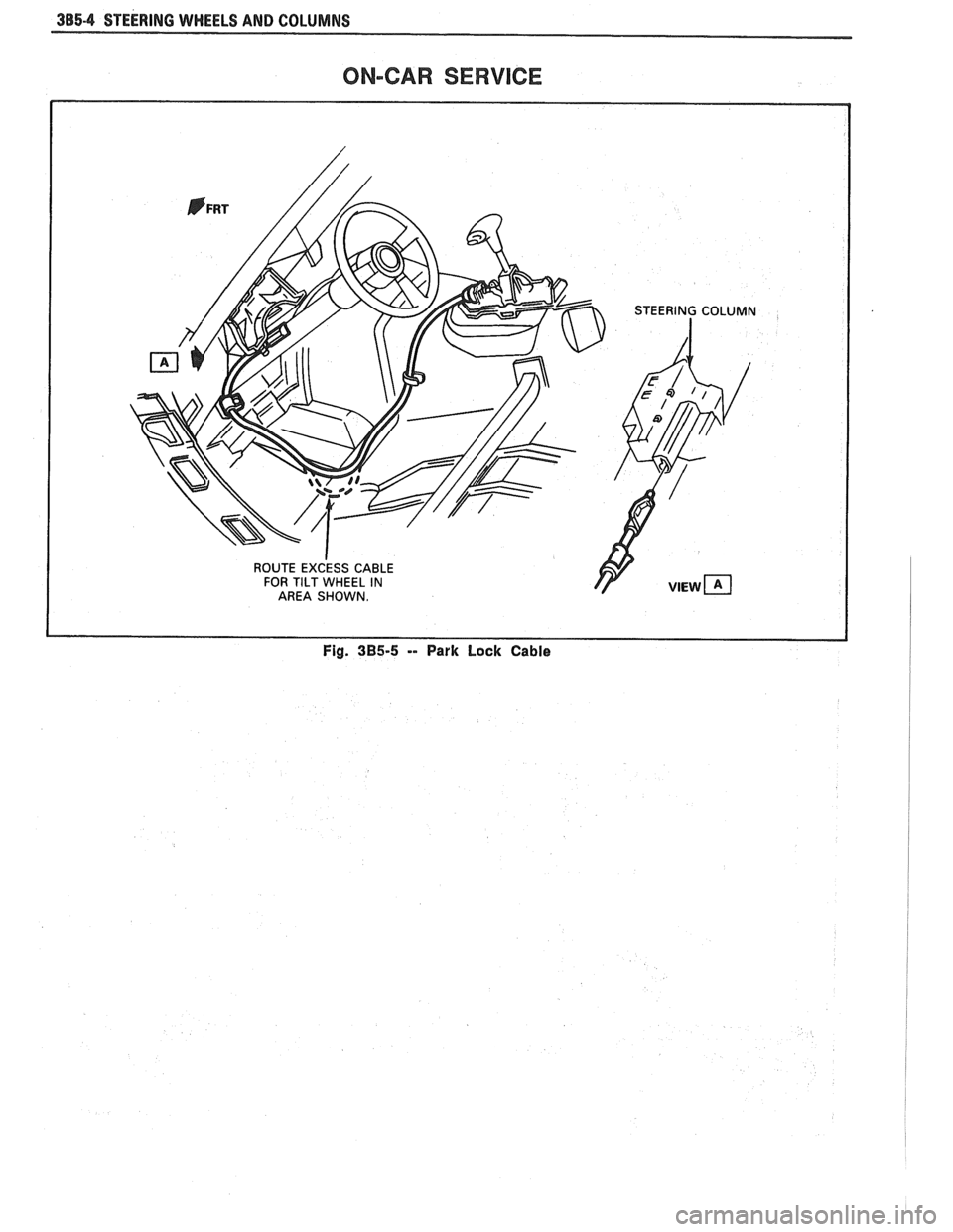
385-4 STEERING WHEELS AND COLUMNS
ON-CAR SERVICE
Fig. 3B5-5 -- Park Lock Cable
Page 156 of 1825
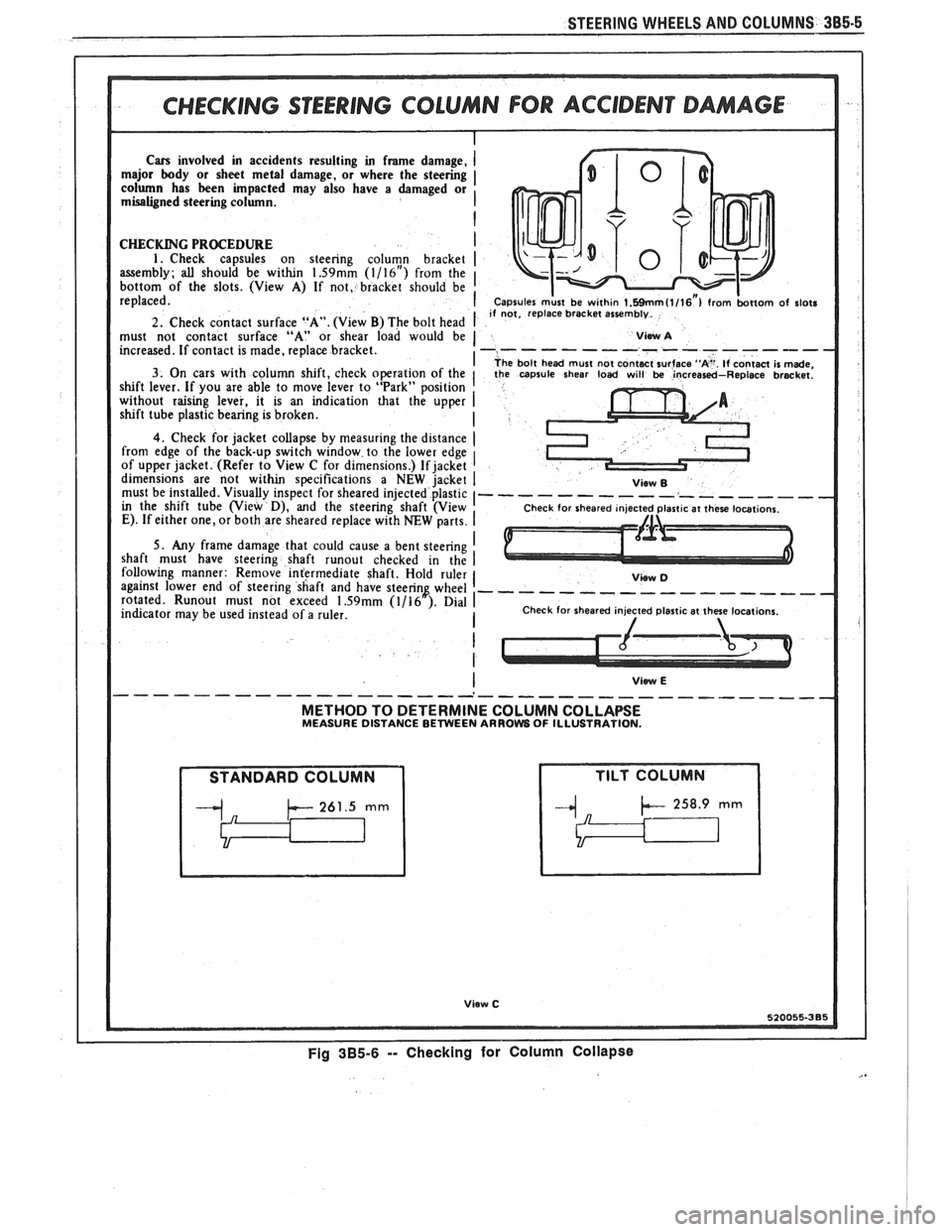
STEERING WHEELS AND COLUMNS 385-6
Cars involved in accidents resulting in frame damage,
major body or sheet metal damage, or where the steering
column has
been impacted may also have a damaged or
misaligned steering column.
2. Check contact surface "A". (View B) The bolt head I must not contact surface "A" or shear load would be 1 Visw A
increased. If contact is made, replace bracket. -----------------
I ;he bolt head must not contect surface "A". If contact is made, 3. On cars with column shift, check operation of the I the capsule sheer load w~ll be increased-Replace brecket. shift lever. If you are able to move lever to "Park" posltion without raising lever, it IS an indication that the upper I shift tube plastic bearing is broken.
4. Check for jacket collapse by measuring the dlstance ( from edge of the back-up switch wlndow to the lower edge
of upper jacket. (Refer to View C for dimenslons.) If jacket dimenslons are not within specificat~ons a NEW jacket I must be instatled. Visually inspect for sheared injected plastlc I------- in the shift tube (V~ew D), and the steering shaft (View E). If either one, or both are sheared replace w~th NEW parts. I
MEASURE DISTANCE BETWEEN ARROW OF ILLUSTRATION.
Viaw C
~ig 3~5-6 -- Checking for Column Collapse
Page 157 of 1825
385.8 STEERING WHEELS AND COLUMNS
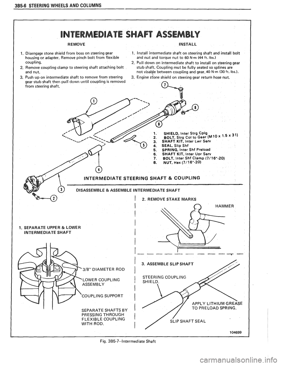
INTERMEDIATE SHAFT ASSEMBLY
REMOVE
1. Disengage stone shield from boss on steering gear
housing or adapter. Remove pinch bolt from flexible
coupling.
2. Remove coupling clamp to steering shaft attaching bolt
and nut.
3. Push up
on intermediate shaft to remove from steering
gear stub shaft then pull down until coupling is removed
from steering shaft. INSTALL
1. Install
intermediate shaft on steering shaft and install bolt
and nut and torque nut to 60 N.m (44 ft. Ibs.)
2. Pull down on intermediate shaft to install on steering gear
stub shaft. Coupling mut be fully seated so splines are
not visa
le between coupling and gear. 40 N.m (30ft. Ibs.).
3. Engine 4 one shield on steering gear return hose nut.
1. SHIELD, lnter Strg Cplg 2. BOLT, Str~ Col to Gear (MI0 31) 3. SHAFT KIT, lnter Lwr Sew 4. SEAL, Sl~p Shf 5. SPRING, lnter Shf Preload 6. SHAFT KIT, lnter UD~ Sew 7. BOLT, lnter Shf Clamp (7/16"-20) 8. NUT, Hex (7/16"-20)
1 2. REMOVE STAKE MARKS
1. SEPARATE UPPER & LOWER
INTERMEDIATE SHAFT
3/8" DIAMETER ROD
LOWER COUPLING
ASSEMBLY
COUPLING SUPPORT
SEPARATE SHAFTS BY
PRESSING THROUGH
FLEXIBLE COUPLING
WITH ROD. HAMMER
3. ASSEMBLE SLIP SHAFT /
STEERING COUPLING
SHIELD.
APPLY LITHIUM GREASE / // TO PRELOAD SPRING.
/ SLlP SHAFT SEAL
Fig. 385-7--Intermediate Shaft
Page 158 of 1825
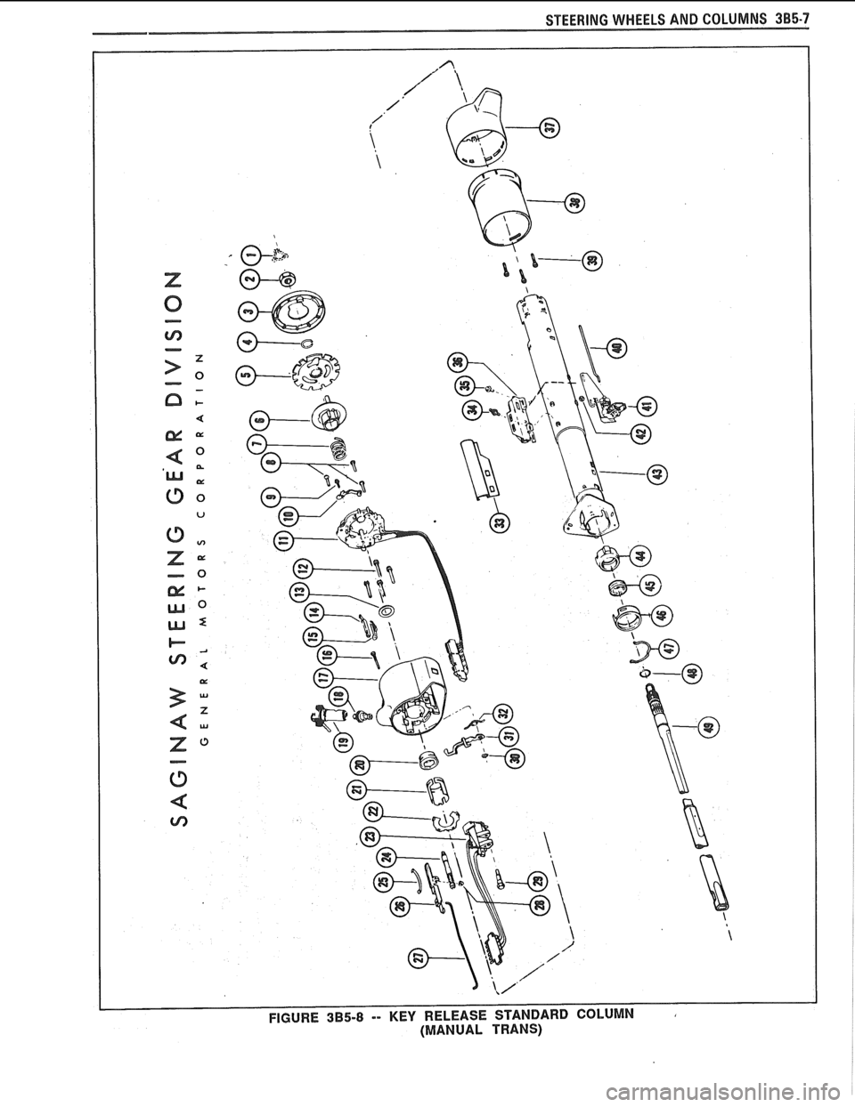
STEERING WHEELS AND COLUMNS 385-7
Page 159 of 1825
V)V) V,
5; E ;;I: -4-4 w my, 00 4 s- s zg By, " e, Om- B 4a 2 Oy, cs a gg o, ?gxcpB
0 -4:zz =A L ZR
5; "5 -4 Zi X(P, -4 50 -
oz
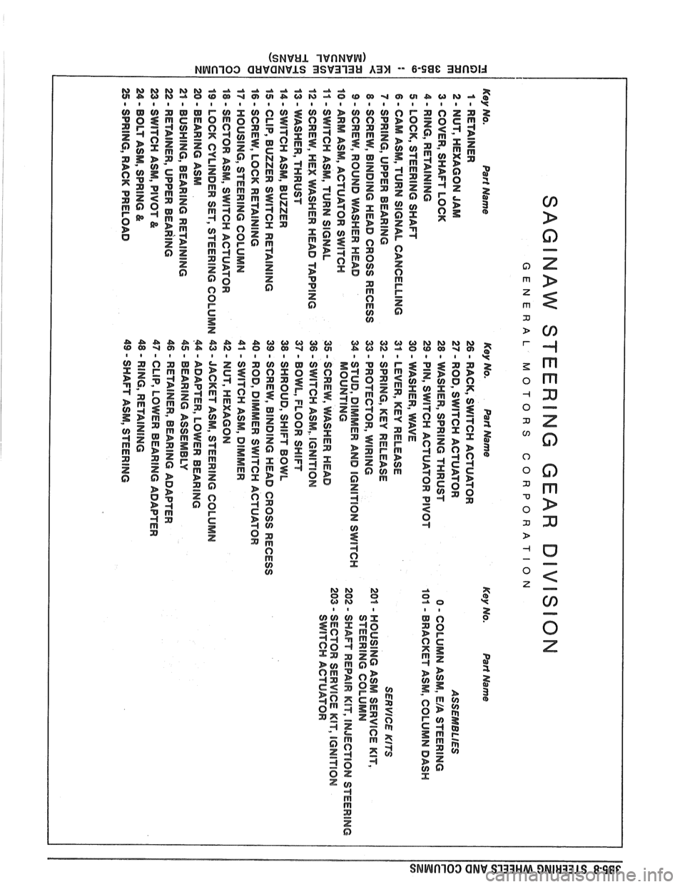
SNUUn183 QNV S133HM 9Nlt1331S %98€
Page 160 of 1825
STEERING WHEELS AND COLUMNS 385-9
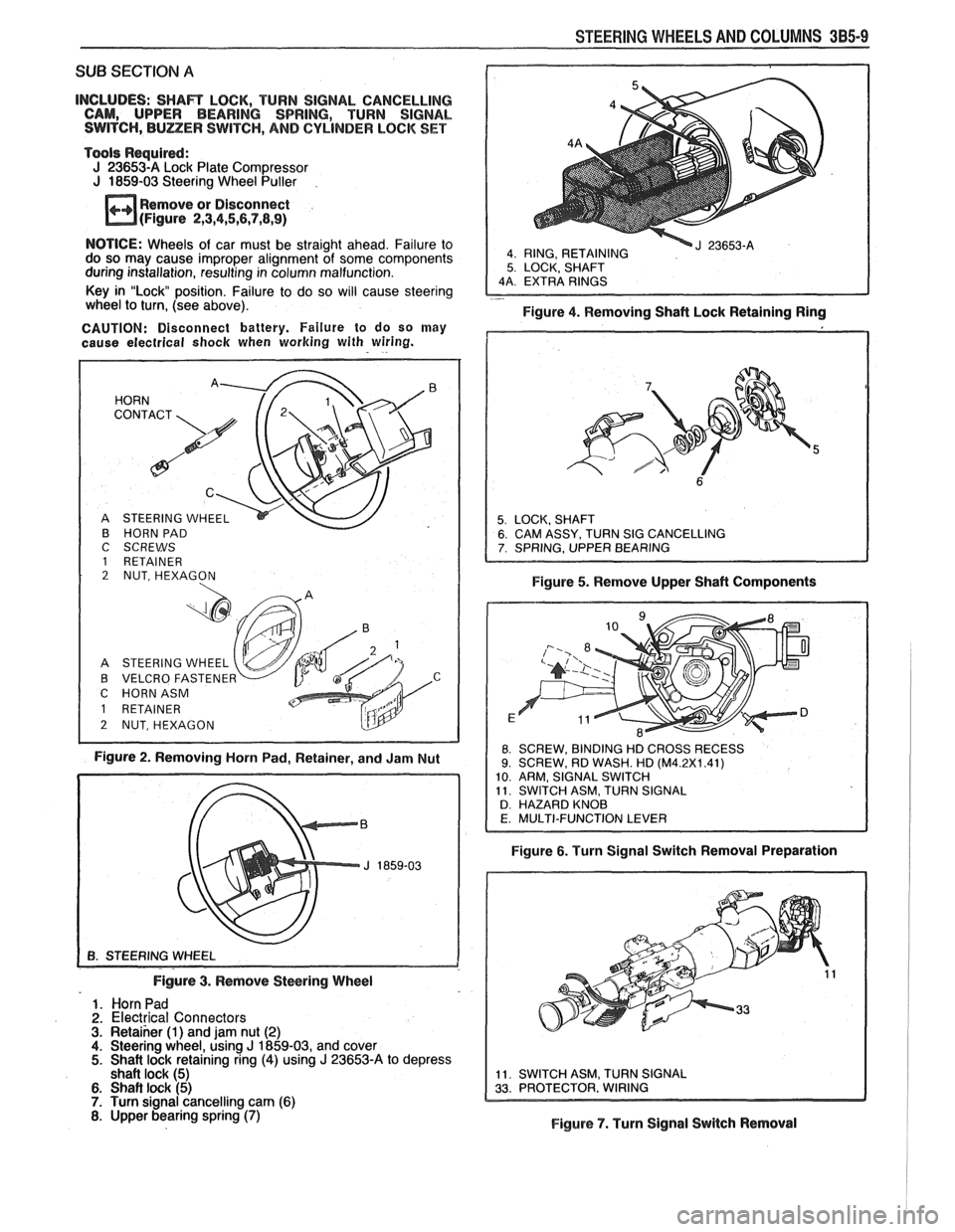
SUB SECTION A
INCLUDES: SHAR LOCK, TURN SIGNAL CANCELLING
CAM, UPPER BEARING SPRING, TURN SIGNAL
SWITCH,
BULZER SWITCH, AND CYLINDER LOCK SET
Tools Required:
J 23653-A Lock Plate Compressor
J 1859-03 Steering Wheel Puller
Remove or Disconnect
(Figure
2,3,4,5,6,7,8,9)
4 RING, RETAINING 5 LOCK, SHAFT
NOTICE: Wheels of car must be straight ahead. Failure to
do so may cause improper alignment of some components
during installation, resulting in column malfunction.
Key in "Lock position. Failure to do so will cause steering
- wheel to turn, (see above).
Figure 4. Removing Shaft Lock Retaining Ring
CAUTION: Disconnect battery. Failure to do so may
cause electrical
shock when working with wiring.
B HORN PAD
C SCREWS
1 RETAINER 2 NUT, HEXAGON
A STEERING WHEEL
B VELCRO FASTENE
C HORNASM
Figure 2. Removing Horn Pad, Retainer, and Jam Nut Figure
5. Remove Upper Shaft Components
8 SCREW,
BINDING HD CROSS RECESS 9. SCREW, RD WASH. HD (M4.2X1.41)
10 ARM, SIGNAL SWITCH
11 SWITCH ASM, TURN SIGNAL
D HAZARD KNOB
Figure 6. Turn Signal Switch Removal Preparation
Figure
3. Remove Steering Wheel
1. Horn Pad
2. Electrical Connectors 3. Retaiher (1) and jam nut (2) 4. Steering wheel, using J 1859-03, and cover 5. Shait lock retaining ring (4) using J 23653-A to depress
shaft lock (5)
6. Shaft lock (5) 7. Turn signal cancelling cam (6) 8. Upper bearing spring (7) Figure 7. Turn Signal Switch Removal