PONTIAC FIERO 1988 Service Repair Manual
Manufacturer: PONTIAC, Model Year: 1988, Model line: FIERO, Model: PONTIAC FIERO 1988Pages: 1825, PDF Size: 99.44 MB
Page 1641 of 1825
8E -14 WINDSHIELD WIPER SYSTEMS - F CARLINE
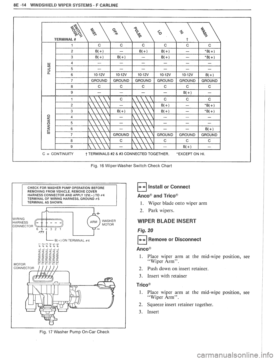
Fig. 16 Wiper-Washer Switch Check Chart
CHECK FOR WASHER PUMP OPERATION BEFORE
REMOVING FROM VEHICLE. REMOVE COVER
HARNESS CONNECTOR AND APPLY
12V(+) TO #4 TERMINAL OF WIRING HARNESS, GROUND #5 TERMINAL AS SHOWN.
WIRING HARNESS
CONNECTOR WASHER
MOTOR
B(+) ON TERMINAL #4 -~mwli)w **st***
Fig. 17 Washer Pump On-Car Check
Install or Connect
AncoB and Tricoa
1. Wiper blade onto wiper arm
2. Park wipers.
WIPER BLADE INSERT
Fig. 20
Remove or Disconnect
Ancoa
1. Place wiper arm at the mid-wipe position, see
"Wiper Arm".
2. Push down on insert retainer.
3. Insert with retainer
TricoB
I. Place wiper arm at the mid-wipe position, see
"Wiper Arm".
2. Squeeze insert retainer together.
3. Insert
Page 1642 of 1825
WINDSHIELD WIPER SYSTEMS F CARLlNE BE -15
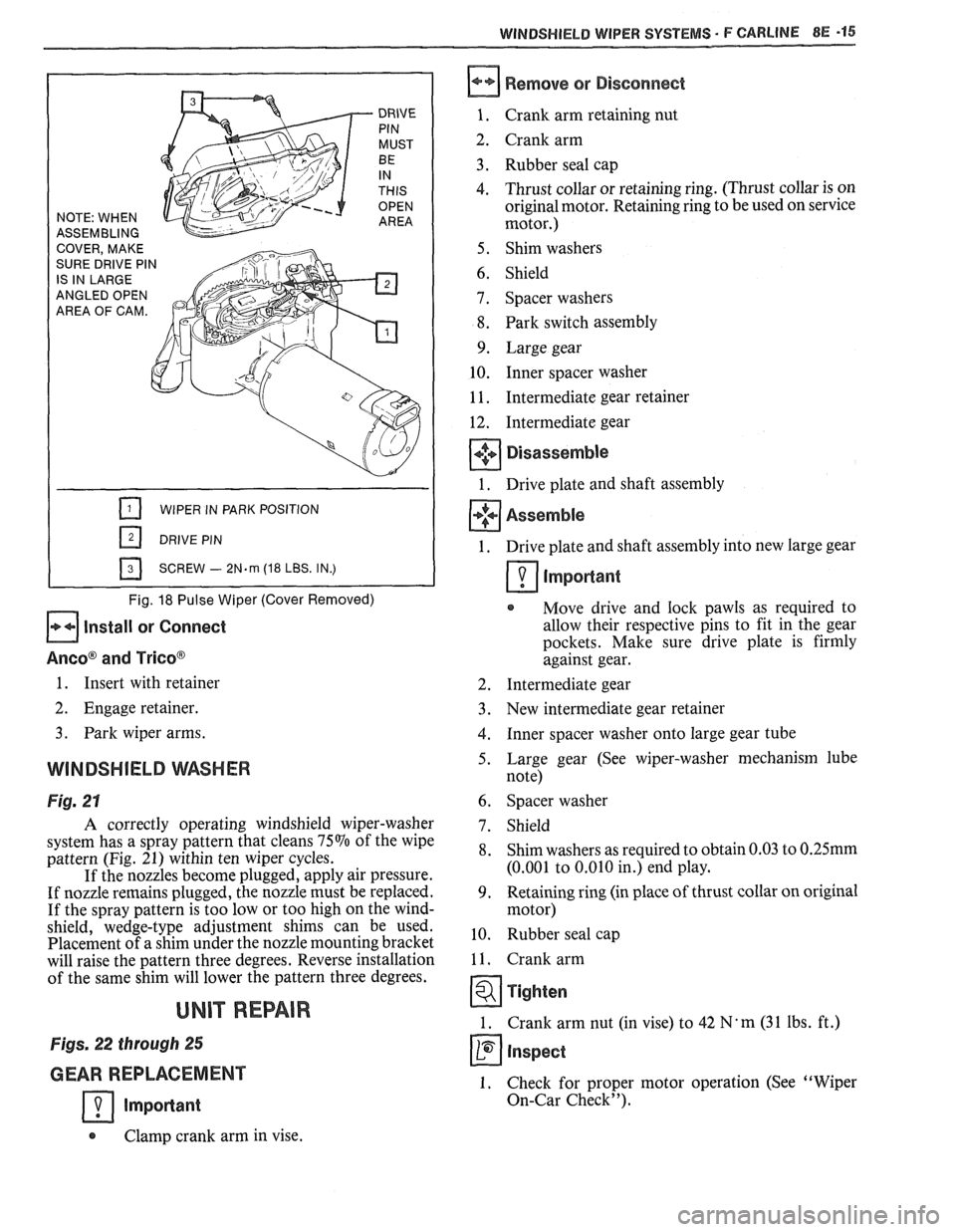
ASSEMBLING
ANGLED OPEN
AREA OF CAM.
WIPER IN PARK POSITION
SCREW
- 2N.m (18 LBS. IN.)
Fig. 18 Pulse Wiper (Cover Removed)
Install or Connect
Aneo@ and Trico@
Remove or Disconnect
Crank arm retaining nut
Crank arm
Rubber seal cap
Thrust collar or retaining ring. (Thrust collar is on
original motor. Retaining ring to be used on service
motor.)
Shim washers
Shield
Spacer washers
Park switch assembly
Large gear Inner spacer washer
Intermediate gear retainer
Intermediate gear
Disassemble
Drive plate and shaft assembly
Assemble
1. Drive plate and shaft assembly into new large gear
Important
Move drive and lock pawls as required to
allow their respective pins to fit in the gear
pockets. Make sure drive plate is firmly
against gear.
1. Insert with retainer 2. Intermediate gear
2. Engage retainer. 3. New intermediate gear retainer
3. Park wiper arms. 4. Inner spacer washer onto large gear tube
WINDSHIELD WASHER 5. Large gear (See wiper-washer mechanism lube
note)
Fig. 21 6. Spacer washer
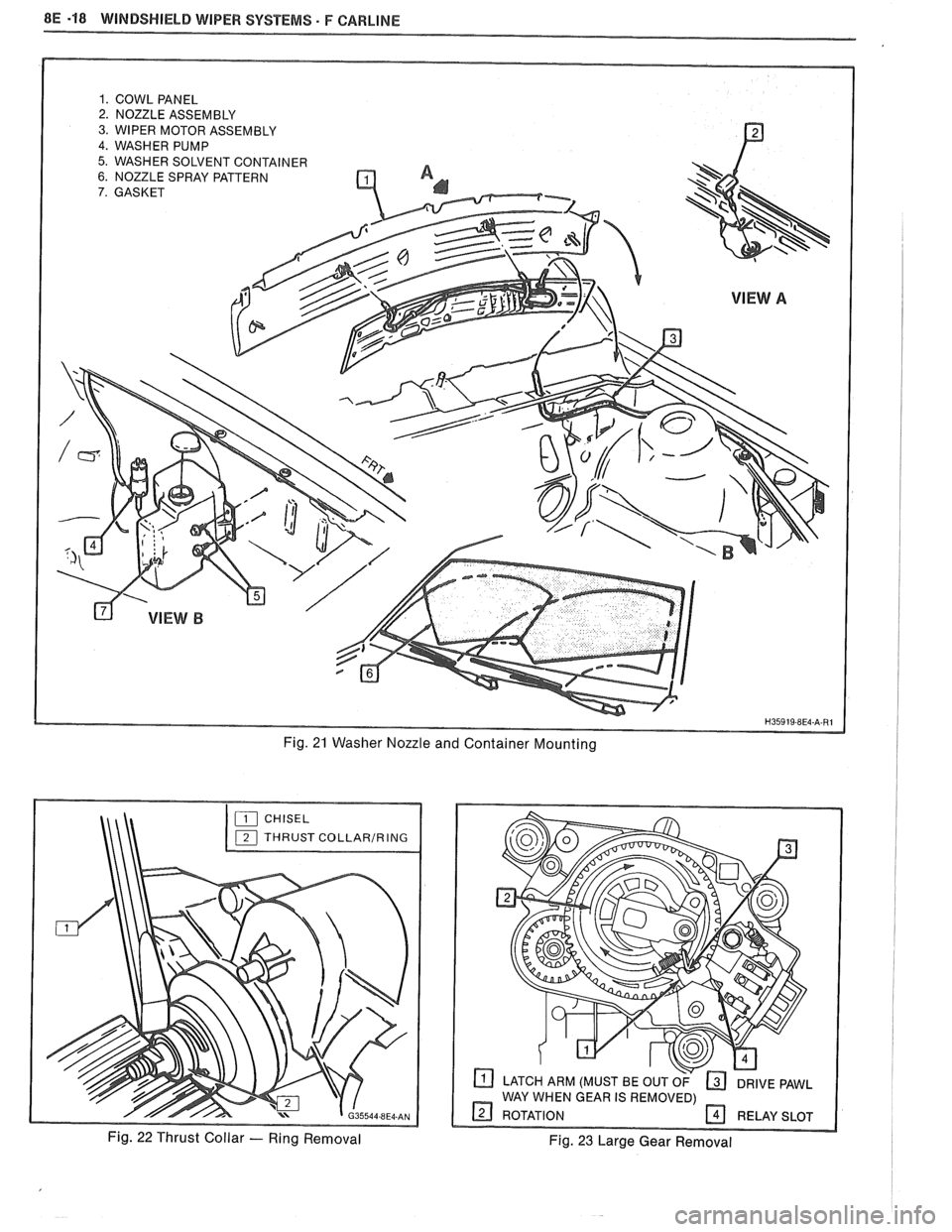
A correctly operating windshield wiper-washer
system has a spray pattern that cleans
75% of the wipe
pattern (Fig. 21) within ten wiper cycles.
If the nozzles become plugged, apply air pressure.
If nozzle remains plugged, the nozzle must be replaced.
If the spray pattern is too low or too high on the wind-
shield, wedge-type adjustment shims can be used.
Placement of a shim under the nozzle mounting bracket
will raise the pattern three degrees. Reverse installation
of the same shim will lower the pattern three degrees.
UNIT REPAIR
Figs. 22 through 25
GEAR REPLACEMENT
Important
7. Shield
8. Shim washers as required to obtain 0.03 to 0.25mm
(0.001 to 0.010 in.) end play.
9. Retaining ring (in place of thrust collar on original
motor)
10. Rubber seal cap
11. Crank arm
Tighten
1. Crank arm nut (in vise) to 42 N' m (3 1 Ibs. ft.)
Inspect
1. Check for proper motor operation (See "Wiper
On-Car Check").
Clamp crank arm in vise.
Page 1643 of 1825
8E -16 WINDSHIELD WIPER SYSTEMS - F CARLINE
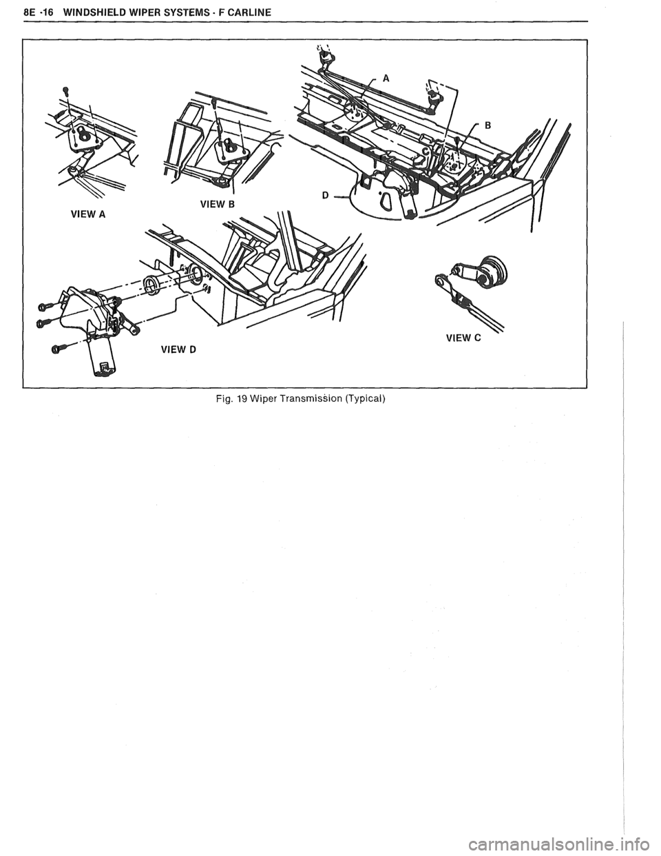
Fig. 19 Wiper Transmission (Typical)
Page 1644 of 1825
WiNDSWlEbB WIPER SYSTEMS - F CARLINE 8E -47
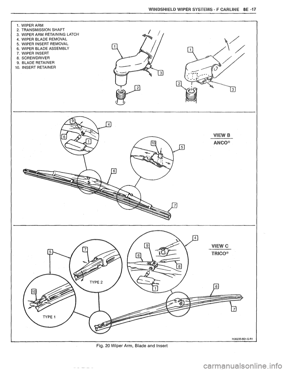
1. WlPER ARM
2. TRANSMISSION SHAFT
3. WIPER ARM RETAINING LATCH 4. WlPER BLADE REMOVAL
5. WlPER INSERT REMOVAL
6. WlPER BLADE ASSEMBLY 7. WlPER INSERT
8. SCREWDRIVER
9. BLADE RETAINER
10. INSERT RETAINER
Fig. 20 Wiper Arm, Blade and Insert
Page 1645 of 1825
8E -18 WINDSHIELD WIPER SYSTEMS. F CAWLINE
1. COWL PANEL 2. NOZZLE ASSEMBLY
3. WIPER MOTOR ASSEMBLY
4. WASHER PUMP
5. WASHER SOLVENT CONTAINER 6. NOZZLE SPRAY PATTERN
7. GASKET
Fig. 21 Washer Nozzle and Container Mounting
CHISEL
THRUST
COLLARIRING
Fig. 22 Thrust Collar - Ring Removal
LATCH ARM (MUST BE OUT OF DRIVE PAWL
WAY WHEN GEAR IS REMOVED)
9 ROTATION RELAY SLOT
Fig. 23 Large Gear Removal
Page 1646 of 1825
WINDSHIELD WIPER SYSTEMS - F CARLINE BE -19
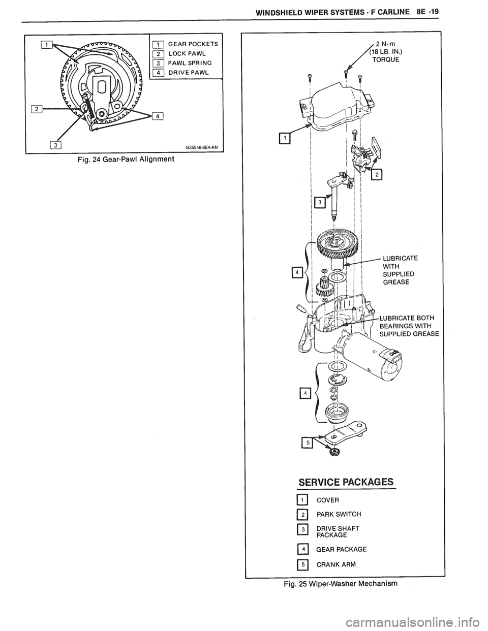
LOCK PAWL
Fig. 24 Gear-Pawl Alignment
LUBRICATE BOTH
BEARINGS WITH
SERVICE PACKAGES
COVER
DRIVESHAFT PACKAGE
GEAR PACKAGE
CRANK ARM
Fig. 25 Wiper-Washer Mechanism
Page 1647 of 1825

Page 1648 of 1825
F CARLINE ACCESSORIES 9-1
SECTION 9
ACCESSOR
CONTENTS
0 & ANTENNAS 9A
SE CONTROL 9B
SCELLANEOUS ACCESSOR ES 9G
Page 1649 of 1825

Page 1650 of 1825
RADIO SYSTEMS AND ANTENNAS 9A-1
SECTION 9A
0 SYSTEMS AND ANTENNAS
CONTENTS
............................................. General Description .................................... 9A-1 Radio Operation 9A-4
Radio
............................................................ 9A-1 ETR AM/FM Stereo (UM-7) ....................... 9A-4
Antennas
........................................................ 9A- 1 ETR Stereo Cassette (UM-6) ......................... 9A-5
Fixed Antenna
.......................................... 9A- 1 ETR Stereo/Cassette/Eaualizer
Diagnosis ........................................................
Radio ....................... .. ................................
Static and Noise .................................... .....
........................................ Popping Noise
Preliminary Diagnostics
.............................
Antenna ................................. .. ................
Tape Player .................. .... .......................
Service Procedures ....................................
Radio and Speakers ........................... .............
Radio Noise Suppression Equipment ............
Stereo Cassette Tape Player ..........................
Tape & Tape Player Care ........................
(UX-1) ..................................................... 9A-6
Advanced ETR
Stereo/Cassette/Equalizer Touch
Control
.................................... ... .............. 9A-7
On-Car Service .............................................. 9A-9
Radio Receiver
............................................ 9A-9
Radio Steering Wheel Controls
..................... 9A-9
Audio Amplifier
........................................... 9A-9
Radio Suppression
..................................... 9A-9
Front Speaker
................................................. 9A-9
............... Rear Speaker; Sub Woofer Speaker
9A-9
Antenna
..................... .. ............................. 9A- 10
GENERAL DESCRIPUION
RADIO ANTENNAS
For radios and radio use see the "Radio Fixed Antenna
Operation" section. ETR means 'Electronically Tuned The
fixed antenna on the right front fender
Receiver'. cannot be adjusted up or down. It may provide
improved reception in rural areas.
- The fixed antenna is designed to withstand most
car washes without damage. If the antenna becomes
slightly bent, you can straighten it by hand. The
antenna can be replaced if severely bent (by vandalism,
etc.). Antennas must be kept clean for good
performance.
RADIO
Because radio problems are normally repaired at
authorized warranty repair stations, the tendency is to
remove the set when a problem is reported, without any
preliminary diagnosis. This results in a large number
of radios being "No Trouble Found" units when
received by the warranty repair stations. Often the
trouble can be corrected without radio removal. wire.
If equipped with
A/C, the blower motor has a
built-in capacitor. Extra electrical equipment added to
the static if not properly grounded or wiring was
improperly routed.
Weak
FM station reception will be affected by
nearby buildings, car speed and direction. These
"flutter" and "fading" conditions are characteristic of
weak FM signals.
ETR radios require clock and button reset if the
battery is disconnected.
Popping Noise
Static and Noise Operating devices such as turn signals, pushing in
cigarette lighter, operating stop lights, etc., may cause
Ground strap connections must be clean and
a popping noise on distant (weak) AM signals.
tight, spark plug cables must be TVRS type and in
good condition and resistance-type spark plugs used.
Preliminary Diagnostics
Capacitors are used in the generator, heating/air
conditioning system, and fuse panel to reduce noise
The inconvenience of driving without a radio
entering the radio through the feed wires. If the car has
while the set is being serviced can often be avoided if
a heater only, the capacitor is in the blower motor feed
the following quick checks are used to eliminate