PONTIAC FIERO 1988 Service Repair Manual
Manufacturer: PONTIAC, Model Year: 1988, Model line: FIERO, Model: PONTIAC FIERO 1988Pages: 1825, PDF Size: 99.44 MB
Page 1681 of 1825

Page 1682 of 1825
GENERAL INFORMATION - F STYLE 1 H-1
SECTION IH
GENERAL NFORMAT
NOTICE: The anti-theft label found on some major sheet metal, engines, and transmissions must be masked
prior to painting, rustproofing, undercoating, etc. The mask
must be removed following the above operations.
Failure to keep the label clean and readable may result in liability for violation of Federal Vehicle Theft Prevention
Standard, and subject the vehicle owner to possible suspicion that the part was stolen.
Lock Cylinder Coding
..................................... I H-1 Chip Resistant Plastisol Material .................... 1 H-8
...................................................... Lubrication 1 H-2 Flexible Exterior Plastic Parts ......................... 1H-9
Adhesive Body Side Moldings ......................... 1H-3 Metal Replacement Parts Finishing ................ lH-13
Waterleak Diagnosis and Repair ..................... 1H-3 Interior Plastic Trim Parts Finishing .............. 1H-13
.................................................... Anticorrosion Treatment ................................ IH-4 Special Tools I H- 14
LOCK CYL!NDER CODING o Check key operation in the lock cylinder.
KEY IDENTIFICATION AND USAGE
REPLACEMENT LOCK CYLINDERS
The lock cylinder keyway is designed so that
other model keys will not enter a current model lock
cylinder. Two noninterchangeable keys are used.
CB Square headed key is used in the ignition lock
cylinder.
o Oval headed key is used in all other lock
cylinders.
Key identification is obtained from the four
character key code stamped on the knockout portion
of the key head and an identification letter stamped on
the key shank. After the code number has been
recorded by the owner, the plugs should be knocked
out of the key head. From these numbers, the lock
combination can be determined by use of a code list
(available to owners of key cutting equipment from
equipment suppliers). If key code numbers are not
available from records or from the knockout plug, the
lock combination (tumbler numbers and position) can
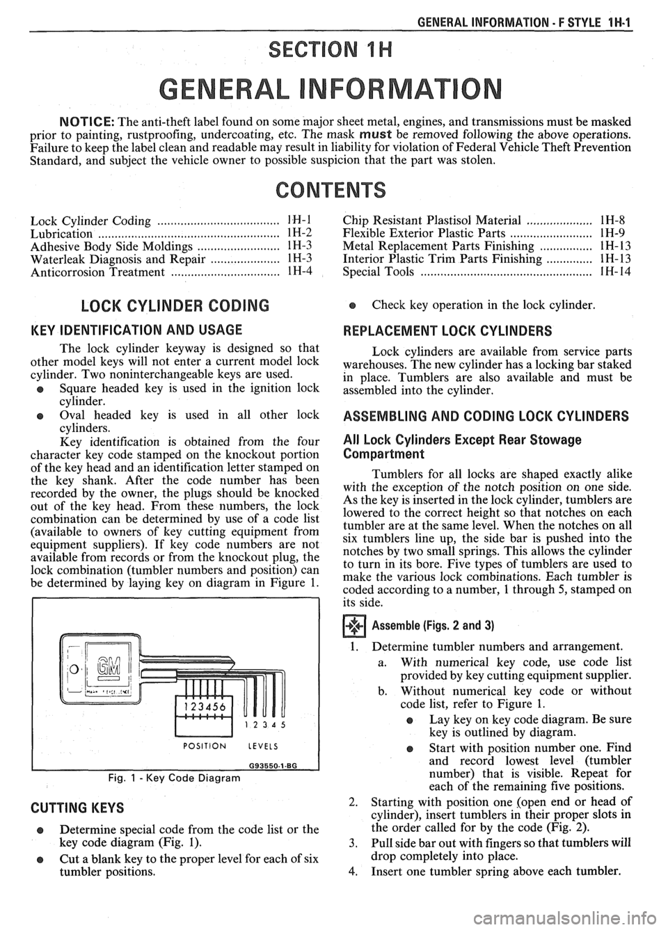
be determined by laying key on diagram in Figure
1.
I POSITION LEVELS I
Fig. 1 - Key Code Diagram
CUTTING KEYS
Lock cylinders are available from service parts
warehouses. The new cylinder has a locking bar staked
in place. Tumblers are also available and must be
assembled into the cylinder.
ASSEMBLING AND CODING LOCK CYLINDERS
All Lock Cylinders Except Rear Stowage
Compartment
Tumblers for all locks are shaped exactly alike
with the exception of the notch position on one side.
As the key is inserted in the lock cylinder, tumblers are
lowered to the correct height so that notches on each
tumbler are at the same level. When the notches on all
six tumblers line up, the side bar is pushed into the
notches by two small springs. This allows the cylinder
to turn in its bore. Five types of tumblers are used to
make the various lock combinations. Each tumbler is
coded according to a number,
1 through 5, stamped on
its side.
Assemble (Figs. 2 and 3)
1. Determine tumbler numbers and arrangement.
a. With numerical
key code, use code list
provided by key cutting equipment supplier.
b. Without numerical
key code or without
code list, refer to Figure
1.
o Lay key on key code diagram. Be sure
key is outlined by diagram.
Determine special code from the code list or the
key code diagram (Fig.
1). 3.
o Cut a blank key to the proper level for each of six
tumbler positions.
4.
Start with position number one. Find
and record lowest level (tumbler
number) that is visible. Repeat for
each of the remaining five positions.
Starting with position one [open end or head of
cylinder), insert tumblers in their proper slots in
the order called for by the code (Fig.
2).
Pull side bar out with fingers so that tumblers will
drop completely into place.
Insert one tumbler spring above each tumbler.
Page 1683 of 1825
1 H-2 GENERAL INFORMATION - F STYLE
5. Insert spring retainer so that end prongs slide into
upon cylinder type. Therefore only the last 4 or 5
the slots at each end of cylinder. Press retainer
tumbler combinations are required.
down.
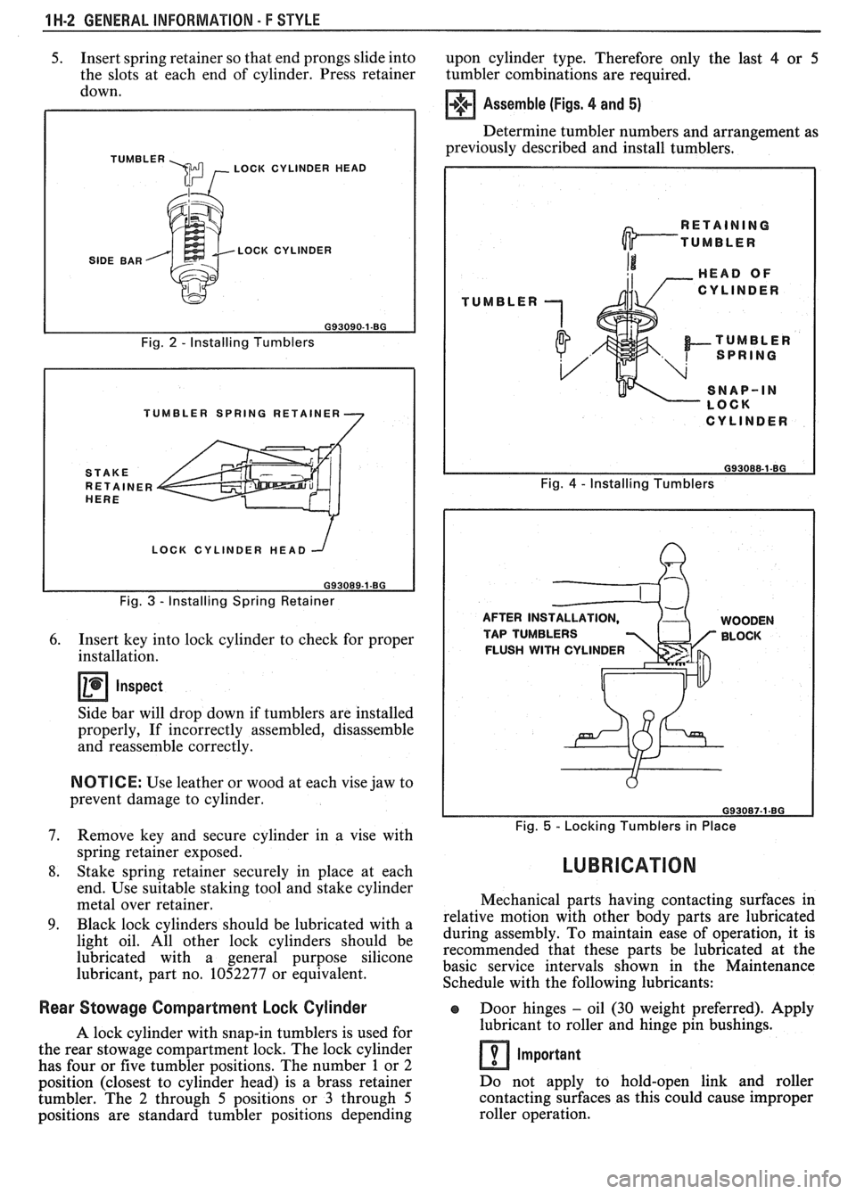
TUMBLER \m , LOCK CYLINDER HEAD
SIDE BAR LOCK CYLINDER
Fig.
2 - Installing Tumblers
TUMBLER SPRING RETAINER
LOCK CYLINDER HEAD
Fig.
3 - Installing Spring Retainer
6. Insert key into lock cylinder to check for proper
installation.
Inspect
Side bar will drop down if tumblers are installed
properly, If incorrectly assembled, disassemble
and reassemble correctly.
NOTICE: Use leather or wood at each vise jaw to
prevent damage to cylinder.
7. Remove key and secure cylinder in a vise with
spring retainer exposed.
8. Stake spring retainer securely in place at each
end. Use suitable staking tool and stake cylinder
metal over retainer.
9. Black lock cylinders should be lubricated with a
light oil. All other lock cylinders should be
lubricated with a general purpose silicone
lubricant, part no. 1052277 or equivalent.
Assemble (Figs. 4 and 5)
Determine tumbler numbers and arrangement as
previously described and install tumblers,
TUMBLER
I CYLINDER I
Fig. 4 - Installing Tumblers
AFTER INS WOODEN
TAP TUMBLERS BLOCK
FLUSH
WITH CYLINDER
Fig. 5 - Locking Tumblers in Place
LUBRICATION
Mechanical parts having contacting surfaces in
relative motion with other body parts are lubricated
during assembly. To maintain ease of operation, it is
recommended that these parts be lubricated at the
basic service intervals shown in the Maintenance
Schedule with the following lubricants:
Rear Stowage Compartment Lock Cylinder Door hinges - oil (30 weight preferred). Apply
A lock cylinder with snap-in tumblers is used for lubricant
to roller and hinge pin bushings.
the rear stowage compartment lock. The lock cylinder
Important has four or five tumbler positions. The number 1 or 2
position (closest to cylinder head) is a brass retainer Do
not apply to hold-open link and roller
tumbler. The
2 through 5 positions or 3 through 5 contacting
surfaces as this could cause improper
positions are standard tumbler positions depending roller operation.
Page 1684 of 1825
GENERAL INFORMAVlOM - F STYLE "1-3
Compartment lid hinges - part no. 1052196,
Lubriplate Auto Lube A; part no.
1052349,
Lubriplate Spray Lube A, part no. 8915,
3M
Lithium Spray Lube or equivalent.
Black lock cylinders
- light oil.
e All other lock cylinders - a general purpose
silicone lubricant, part no. 1052277 or equivalent.
e Seat mechanism and door hardware are covered
in the specific body area sections in this manual.
All weatherstrips should be periodically
lubricated with a silicone paste lubricant, part no.
1052363, or equivalent. A thin film of lubricant
should be applied using a clean cloth.
ADHESIVE BODY SlBE MOLDING
The body side moldings are attached to the body
panels with adhesive tape. To insure a good molding
replacement (new or old moldings), the panel surface
should be warm (21°C to 32°C or 70°F to
90°F), clean
and free of any wax or oily film. Two methods are listed
to attach loose molding ends and completely removed
m~ldings.
Molding End Loose
1. Wash affected area with soap and water and wipe
dry. Wipe panel and adhesive side of molding
with a clean rag using oil-free naphtha or alcohol.
If molding has pulled loose from adhesive
backing (tape remains on body panel), do not
remove tape from body. Clean back of molding
and tape on body with oil-free naphtha or alcohol
and proceed with step 3.
2. If needed, apply a length of masking tape as a
molding guide.
A straightedge may also be used
in most cases.
3. Apply adhesive to back of molding and press in
place. If Loctite
414 adhesive (part no. 1052283)
or equivalent is used, apply constant pressure to
molding for 30 seconds or until a firm bond has
been made.
Molding Completely Removed
1.
Wash affected panel area with soap and water
and wipe dry. Remove all traces of adhesive from
body panel and back of molding using oil-free
naphtha or alcohol.
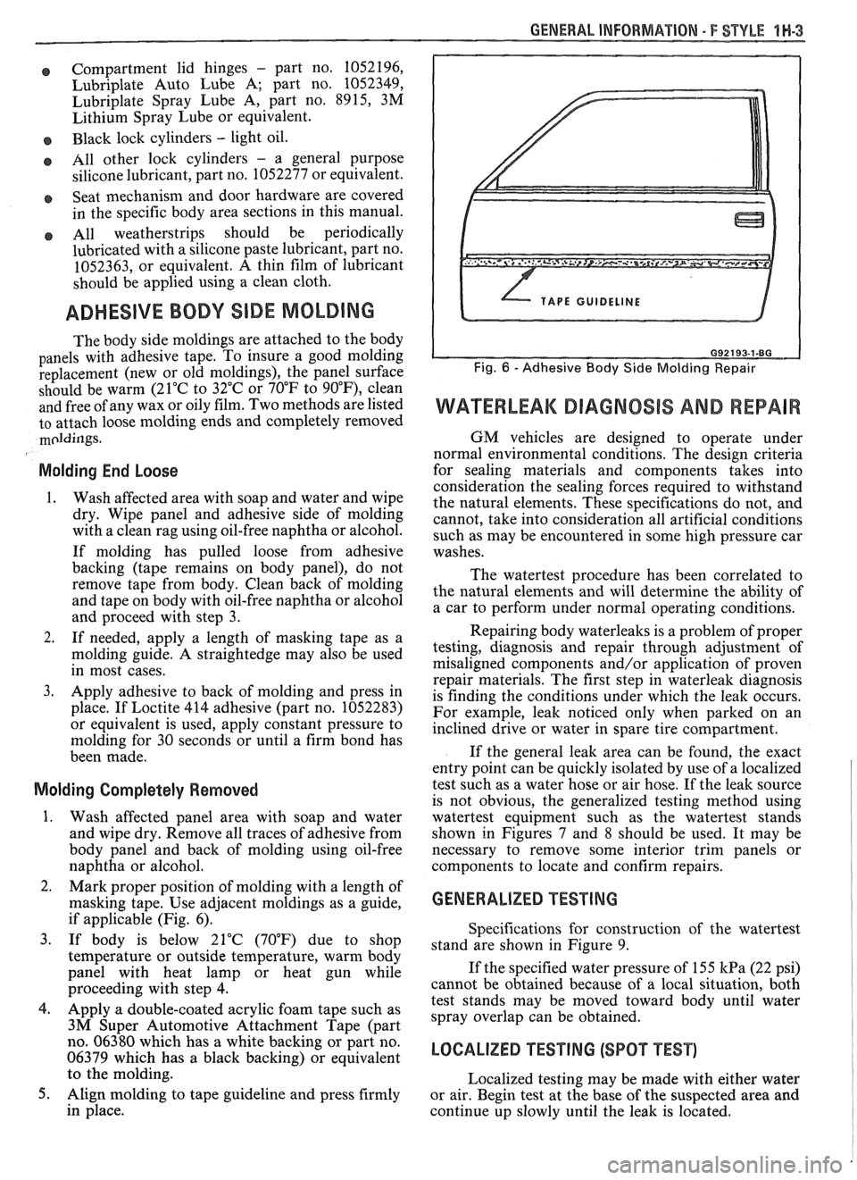
2. Mark proper position of molding with a length of
masking tape. Use adjacent moldings as a guide,
if applicable (Fig. 6).
3. If body is below 21°C (70°F) due to shop
temperature or outside temperature, warm body
panel with heat lamp or heat gun while
proceeding with step
4.
4. Apply a double-coated acrylic foam tape such as
3M Super Automotive Attachment Tape (part
no. 06380 which has a white backing or part no.
06379 which has a black backing) or equivalent
to the molding.
5. Align molding to tape guideline and press firmly
in place.
WATERLEAK DIAGNOSIS AND REPAIR
GM vehicles are designed to operate under
normal environmental conditions. The design criteria
for sealing materials and components takes into
consideration the sealing forces required to withstand
the natural elements. These specifications do not, and
cannot, take into consideration all artificial conditions
such as may be encountered in some high pressure car
washes.
The watertest procedure has been correlated to
the natural elements and will determine the ability of
a car to perform under normal operating conditions.
Repairing body waterleaks is a problem of proper
testing, diagnosis and repair through adjustment of
misaligned components and/or application of proven
repair materials. The first step in waterleak diagnosis
is finding the conditions under which the leak occurs.
For example, leak noticed only when parked on an
inclined drive or water in spare tire compartment.
If the general leak area can be found, the exact
entry point can be quickly isolated by use of a localized
test such as a water hose or air hose. If the leak source
is not obvious, the generalized testing method using
watertest equipment such as the watertest stands
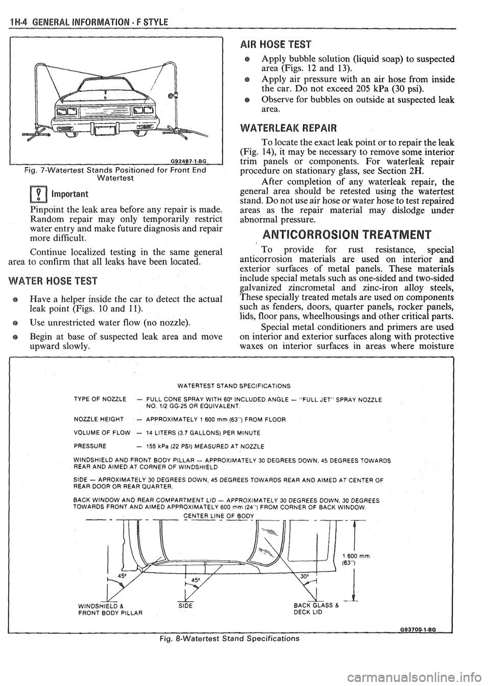
shown in Figures
7 and 8 should be used. It may be
necessary to remove some interior trim panels or
components to locate and confirm repairs.
GENERALIZED TESTING
Specifications for construction of the watertest
stand are shown in Figure 9.
If the specified water pressure of 155
kPa (22 psi)
cannot be obtained because of a local situation, both
test stands may be moved toward body until water
spray overlap can be obtained.
LOCALIZED TEST lNG (SPOT TEST)
Localized testing may be made with either water
or air. Begin test at the base of the suspected area and
continue up slowly until the leak is located.
Page 1685 of 1825
1H-4 GENERAL INFORMATION - F STYLE
Fig. 7-Watertest Stands Positioned for Front End
Watertest
Important
Pinpoint the leak area before any repair is made.
Random repair may only temporarily restrict
water entry and make future diagnosis and repair
more difficult.
Continue localized testing in the same general
area to confirm that all leaks have been located.
WATER HOSE TEST
e Have a helper inside the car to detect the actual
leak point (Figs. 10 and 11).
Use unrestricted water flow (no nozzle).
Begin at base of suspected leak area and move
upward slowly.
AIR HOSE TEST
Apply bubble solution (liquid soap) to suspected
area (Figs. 12 and 13).
Apply air pressure with an air hose from inside
the car. Do not exceed 205
kPa (30 psi).
Observe for bubbles on outside at suspected leak
area.
WATERLEAK REPAIR
To locate the exact leak point or to repair the leak
(Fig.
14), it may be necessary to remove some interior
trim panels or components. For waterleak repair
procedure on stationary glass, see Section
2H.
After completion of any waterleak repair, the
general area should be retested using the watertest
stand. Do not use air hose or water hose to test repaired
areas as the repair material may dislodge under
abnormal pressure.
ANTICORROSION TREATMENT 1 To provide for rust resistance, special
anticorrosion materials are
used on interior and
exterior surfaces of metal panels. These materials
include special metals such as one-sided and two-sided
galvanized zincrometal and zinc-iron alloy steels,
These specially treated metals are used on components
such as fenders, doors, quarter panels, rocker panels,
lids, floor pans, wheelhousings and other critical parts.
Special metal conditioners and primers are used
on interior and exterior surfaces along with protective
waxes on interior surfaces in areas where moisture
WATERTEST STAND SPECIFICATIONS
TYPE OF NOULE
- FULL CONE SPRAY WITH 60' INCLUDED ANGLE - "FULL JET" SPRAY NOZZLE
NO. 112 GG-25 OR EQUIVALENT
NOULE HEIGHT - APPROXIMATELY 1 600 mrn (63") FROM FLOOR
VOLUME OF FLOW
- 14 LITERS (3.7 GALLONS) PER MINUTE
PRESSURE
- 755 kPa (22 PSI) MEASURED AT NOZZLE
WINDSHIELD AND FRONT BODY PILLAR
- APPROXIMATELY 30 DEGREES DOWN, 45 DEGREES TOWARDS
REAR AND AIMED AT CORNER OF WINDSHIELD
StDE - APROXIMATELY 30 DEGREES DOWN, 45 DEGREES TOWARDS REAR AND AIMED AT CENTER OF
REAR DOOR OR REAR QUARTER
BACK WINDOW AND REAR COMPARTMENT LID
- APPROXIMATELY 30 DEGREES DOWN. 30 DEGREES
TOWARDS FRONT AND AIMED APPROXIMATELY 600 rnm (24") FROM CORNER OF BACK WINDOW
CENTER
LINJ OF BODY - --
WINDSHIELD 8. SIDE BACK GLASS & FRONT BODY PILLAR DECK
LID
Fig. &Watertest Stand Specifications
Page 1686 of 1825
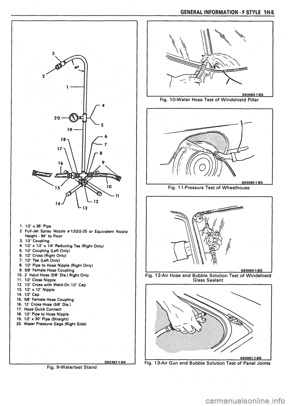
1. 112" x 36" Pipe
2. Full-Jet Spray Nozzle # 112GG-25 or Equivalent Noule Height - 64" to Floor
3. 112" Coupling
4. 112"
x 112" x 114" Reducing Tee (Right Only)
5. 112 Coupling (Left Only)
6. 112" Cross (Right Only)
7. 112" Tee (Left Only)
8. 112" Pipe to Hose Nipple (Right Only)
9. 518" Female Hose Coupling
10. 2'
Input Hose (518" Die.) Right Only
11. 112" Close Nipple
12. 112" Cross with Weld-On 112 Cap
13. 112"
x 12" Nipple
14. 112" Cap
15. 518" Female Hose Coupling
16. 12' Cross Hose
(518" Dia.) 17. Hose Quick Connect
18. 112" Pipe to Hose Nipple
19. 112"
x 30 Pipe (Straight)
20. Water Pressure Gage (Right Side)
Fig. 9-Watertest Stand
GENERAL INFORMATION - F STYLE 1 W-5
Fig. 10-Water Hose Test of Windshield Pillar
Fig.
1 1-Pressure Test of Wheelhouse
Fig. 12-Air Hose and Bubble Solution Test of Windshield
Glass Sealant
093081-1-80
Fig. 13-Air Gun and Bubble Solution Test of Panel Joints
Page 1687 of 1825
1H-6 GENERAL INFOWMATION - F STYLE
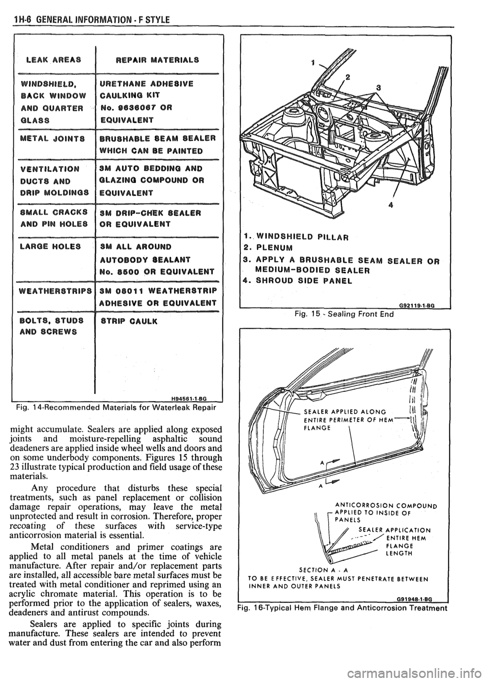
LEAK AREAS I REPAIR MATERIALS
DUCTS AND OLAZlNQ COMPOUND OR
AUTOBODY BEALANT
ADHESIVE OR EQUIVALENT
Fig. 14-Recommended Materials for Waterleak Repair
might accumulate. Sealers are applied along exposed
joints and moisture-repelling asphaltic sound
deadeners are applied inside wheel wells and doors and
on some underbody components. Figures
15 through
23 illustrate typical production and field usage of these
materials.
Any procedure that disturbs these special
treatments, such as panel replacement or collision
damage repair operations, may leave the metal
unprotected and result in corrosion. Therefore, proper
recoating of these surfaces with service-type
anticorrosion material is essential.
Metal conditioners and primer coatings are
applied to all metal panels at the time of vehicle
manufacture. After repair and/or replacement parts
are installed, all accessible bare metal surfaces must be
treated with metal conditioner and
reprimed using an
acrylic chromate material. This operation is to be
performed prior to the application of sealers, waxes,
deadeners and antirust compounds.
1. WINDSHIELD PILLAR
2. PLENUM
3. APPLY A BRUSHABLE SEAM SEALER OR
MEDIUM-BODIED SEALER
4. SHROUD SIDE PANEL
Fig. 15 - Sealing Front End
SEALER APPLIED
ENTIRE PERIMETER OF
FLANGE
ANTICORROSION COMPOUND
APPLIED TO INSIDE OF
SEALER APPLICATION
SECTION A
- A
TO BE EFFECTIVE, SEALER MUST PENETRATE BETWEEN
INNER AND OUTER PANELS
Fig. 16-Typical Hem Flange and Anticorrosion Treatment
Sealers are applied to specific joints during
manufacture. These sealers are intended to prevent
water and dust from entering the car and also perform
Page 1688 of 1825
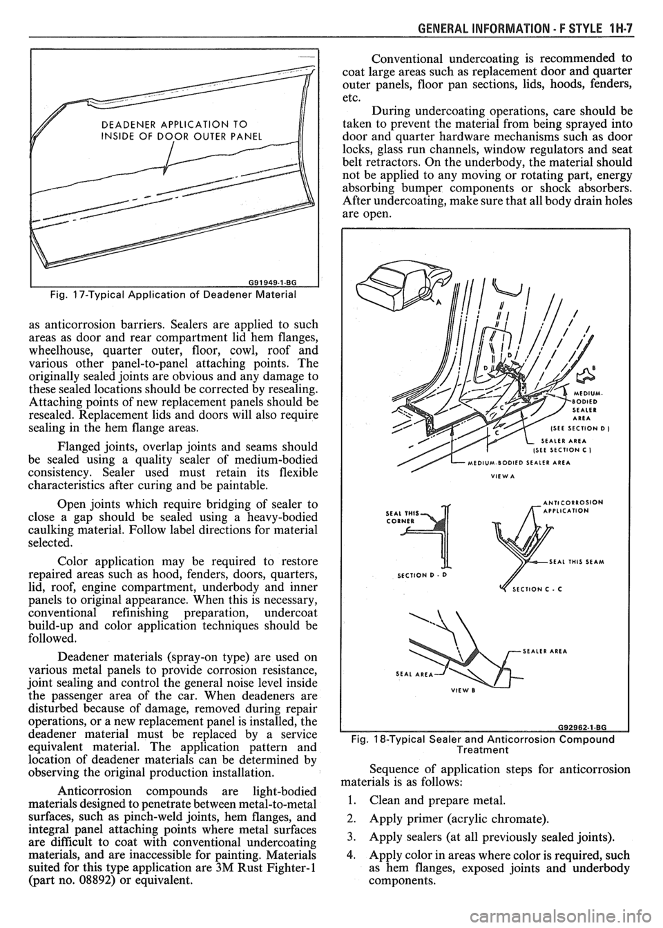
GENERAL INFORMATION - F STYLE IN-7
DEADENER APPLICATION TO
INSIDE OF DOOR OUTER PANEL
I I
Fig. 17-Typical Application of Deadener Material
as anticorrosion barriers. Sealers are applied to such
areas as door and rear compartment lid hem flanges,
wheelhouse, quarter outer, floor, cowl, roof and
various other panel-to-panel attaching points. The
originally sealed joints are obvious and any damage to
these sealed locations should be corrected by resealing.
Attaching points of new replacement panels should be
resealed. Replacement lids and doors will also require
sealing in the hem flange areas.
Flanged joints, overlap joints and seams should
be sealed using a quality sealer of medium-bodied
consistency. Sealer used must retain its flexible
characteristics after curing and be paintable.
Open joints which require bridging of sealer to
close a gap should be sealed using a heavy-bodied
caulking material. Follow label directions for material
selected.
Color application may be required to restore
repaired areas such as hood, fenders, doors, quarters,
lid, roof, engine compartment, underbody and inner
panels to original appearance. When this is necessary,
conventional refinishing preparation, undercoat
build-up and color application techniques should be
followed.
Deadener materials (spray-on type) are used on
various metal panels to provide corrosion resistance,
joint sealing and control the general noise level inside
the passenger area of the car. When deadeners are
disturbed because of damage, removed during repair
operations, or a new replacement panel is installed, the
deadener material must be replaced by a service
equivalent material. The application pattern and
location of deadener materials can be determined by
observing the original production installation.
Anticorrosion compounds are light-bodied
materials designed to penetrate between metal-to-metal
surfaces, such as pinch-weld joints, hem flanges, and
integral panel attaching points where metal surfaces
are difficult to coat with conventional undercoating
materials, and are inaccessible for painting. Materials
suited for this type application are
3M Rust Fighter-1
(part no. 08892) or equivalent. Conventional
undercoating is recommended to
coat large areas such as replacement door and quarter
outer panels, floor pan sections, lids, hoods, fenders,
etc.
During undercoating operations, care should be
taken to prevent the material from being sprayed into
door and quarter hardware mechanisms such as door
locks, glass run channels, window regulators and seat
belt retractors. On the underbody, the material should
not be applied to any moving or rotating part, energy
absorbing bumper components or shock absorbers.
After undercoating, make sure that all body drain holes
are open.
SEAL THIS SEAM
SECTION
D - 0
ECTlON C . C
SEALER AREA
Fig. 18-Typical Sealer and Anticorrosion Compound
Treatment
Sequence of application steps for anticorrosion
materials is as follows:
1. Clean and prepare metal.
2. Apply primer (acrylic chromate).
3. Apply sealers (at all previously sealed joints).
4. Apply color in areas where color is required, such
as hem flanges, exposed joints and underbody
components.
Page 1689 of 1825
1 ti-8 GENERAL INFORMATION - F STYLE
5. Apply deadeners (as indicated by original
application pattern).
6. Apply anticorrosion compounds.
9. Apply underbody rustproofing material.
Cleaning of interior and underbody panel
surfaces is necessary when original galvanized or other
anticorrosion materials have been burned off during
welding or heating operations. Removal of the residue
left from burning will require additional care in such
areas as interior surfaces of box-type construction and
when configurations of the metal panels limit access to
interior surfaces. One or more of the following methods
will remove the residue.
CAUTION: Standard shop practices,
particularly eye protection, should be
followed during these operations to
avoid personal injury.
Where access is possible, scraping can be used. If
a standard putty knife or scraper will not fit into
the affected area, consider fabricating a small,
flexible scraper from a narrow piece of sheet
metal.
e A jet of compressed air will remove most residue
and could be most effective in limited-access
areas. Eye protection is absolutely necessary in an
operation of this type.
e Sandblasting is most effective and should be used
when the equipment is available and access to the
area is good. Sandblasting is an excellent method
for cleanup and preparation of open joints,
underbody components and hem flange areas.
e Wire brushing (power and by hand).
e When access is good, sandpaper and steel wool
can be used.
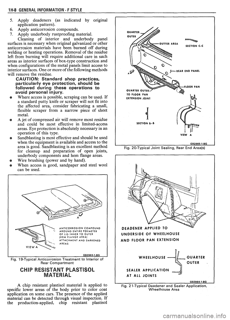
ANTICORROSION COMPOUND AROUND ENTIRE PERIMETER OF LID INNER TO OUTER (HEM FLANGE AREA) ' ATTACHMENT AND DARKENED AREAS
Fig. IS-Typical Anticorrosion Treatment to Interior of Rear Compartment
CHIP RESISTANT PLASTISOL
MATERIAL
A chip resistant plastisol material is applied to
specific lower areas of the body prior to color coat
application on some cars. The presence of the applied
material can be detected through visual inspection. If
the production-applied, chip resistant plastisol
*REAR END PANEL A"'
10 FLOOR PAN
Fig. 20-Typical Joint Sealing, Rear End Area(s)
UNDERSIDE OF WHEELHOUSE
AND FLOOR PAN EXTENSION
WHEELHOUSE QUARTER
OUTER
.
SEALER APPLICATION
AT ALL JOINTS
692964-1.80
Fig. 2 1-Typical Deadener and Sealer Application,
Wheelhouse Area
Page 1690 of 1825
GENERAL INFORMATION - F STYLE 1 H-9
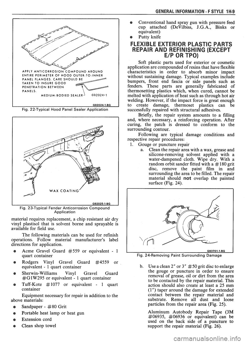
ENTIRE PERIMETER OF HOOD OUTER-TO-INNER
PANEL FLANGES. CARE SHOULD BE TAKEN TO INSURE GOOD
PENETRATION BETWEEN
PANELS.
MEDIUM-BODIED SEALER
Fig. 22-Typical Hood Panel Sealer Application
Fig. 23-Typical Fender Anticorrosion Compound
Application
material requires replacement, a chip resistant air dry
vinyl plastisol that is solvent borne and sprayable is
available for field use.
The following materials can be used for refinish
operations. Follow material manufacturer's label
directions for application.
s Acme Gravel Guard #559 or equivalent - 1
quart container
@ Rodgers Vinyl Gravel Guard #4559 or
equivalent
- 1 quart container
@ Sherwin-Williams Vinyl Gravel Guard
#GlW295 or equivalent - 1 quart container
e Tuff-Kote #I077 or equivalent - 1 quart
container
Equipment necessary for repair in addition to the
above materials:
Sandpaper
- #80 Grit
Portable heat lamp or heat gun
e Extension cord
e Clean shop towel
e Conventional hand spray gun with pressure feed
cup attached
(DeVilbiss, J.G.A., Binks or
equivalent)
s Putty knife
FLEXIBLE EXTERIOR PLASTIC PARTS
REPAIR AND
REFlNlSHlNG (EXCEPT
E/P OR TPO)
Soft plastic parts used for exterior or cosmetic
application are compounded of resins that have flexible
characteristics in order to absorb minor impact
without sustaining damage. Typical examples include
bumpers, front end fascia or side panels such as
fenders. These parts are generally fabricated of
thermosetting plastics which, when cured, cannot be
melted with application of heat such as through hot air
welding. However, if the impact force is great enough
to create damage, thermoset plastics can be
successfully repaired with structural adhesives.
Briefly, the repair system amounts to a filling
and, where necessary, a reinforcing operation. After
curing, the patch is dressed to conform to the
surrounding contour.
Following are typical damage conditions and
respective repair procedures:
1. Gouge or puncture repair
a. Clean the repair area with a wax, grease and
silicone-removing solvent applied with a
water-dampened cloth. Wipe dry. With a
random orbit sander fitted with a
# 180 grit
disc, remove the paint film in and
surrounding the area to be filled. The repair
material should
not overlap the painted
surface (Fig. 24).
Fig. 24-Removing Paint Surrounding Damage
b. Use a clean 2" or 3" # 50 grit disc to enlarge
the gouge or puncture in order to ensure
removal of grease, oil or dirt from the area
to be contacted by the repair material. This
action should also create at least a 25 mm
(1
") taper around the damage for extended
contact between the repair material and
substrate. Remove all dust and loose
particles from the repair area (Fig. 25).
Aluminum
Autobody Repair Tape (3M
#06935, &to6936 or equivalent) can be
used on the back side of a puncture
to
support the repair material (Fig. 26).