PONTIAC FIERO 1988 Service Repair Manual
Manufacturer: PONTIAC, Model Year: 1988, Model line: FIERO, Model: PONTIAC FIERO 1988Pages: 1825, PDF Size: 99.44 MB
Page 1621 of 1825
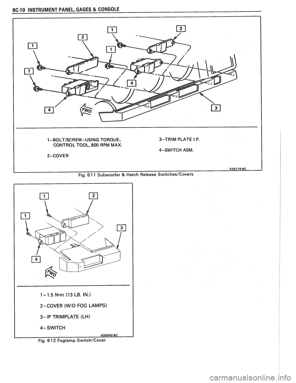
1 -BOLT/SCREW-USING TORQUE, 3-TRIM
PLATE I.P.
CONTROL TOOL, 800 RPM MAX.
4-SWITCI-I ASM.
2-COVER
1 - 1.5 N*m (13 LB. IN.)
I
2- COVER (WIO FOG LAMPS)
I 4- SWITCH I
Fig. 6 1 2 Foglamp Switch/Cover
Page 1622 of 1825
INSTRUMENT PANEL. GAGES & CONSOLE 8C-11
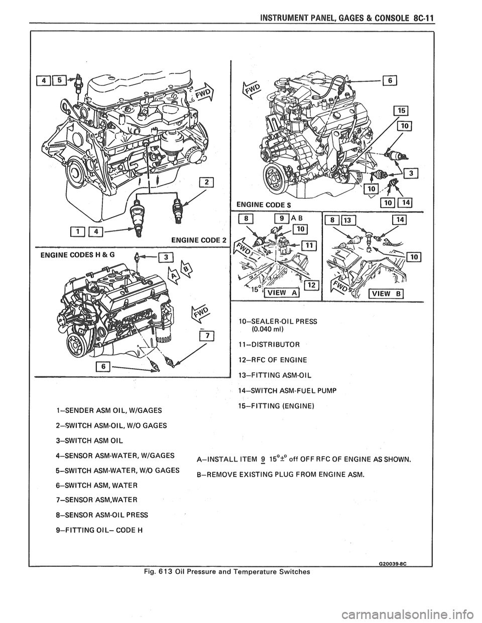
ENGINE CODE 2
ENGINE CODES H & G
10-SEALER-OI L PRESS
(0.040 ml)
12-RFC OF ENGINE
13-FITTING ASM-OIL
14-SWITCH ASM-FUEL PUMP
I
1-SENDER ASM OIL, WIGAGES 15-FITTING (ENGINE)
I
2-SWITCH ASM-OI L, WIO GAGES
3-SWITCH ASM OIL
4-SENS0R ASM-WATER' A-INSTALL ITEM g 15'9 off OFF RFC OF ENGINE AS SHOWN.
ASM-WATER' W1O GAGES B-REMOVE EXISTING PLUG FROM ENGINE ASM.
6-SWITCH ASM, WATER
8-SENSOR ASM-OI L
PR ESS
I 9-FITTING OIL- CODE H
Fig.
6 13 Oil Pressure and Temperature Switches
Page 1623 of 1825
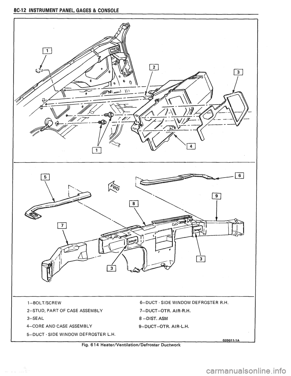
2-STUD, PART OF CASE ASSEMBLY
3-SEAL 7-DUCT-OTR.
AIR-R.H.
8 -DIST. ASM
4-CORE AND CASE ASSEMBLY
9-DUCT-OTR. AI R-L.H.
5-DUCT - SIDE WINDOW DEFROSTER L.H. I
Fig. 6 14 Heater/Ventilation/Defroster Ductwork
Page 1624 of 1825
INSTRUMENT PANEL, GAGES & CONSOLE 8C-13
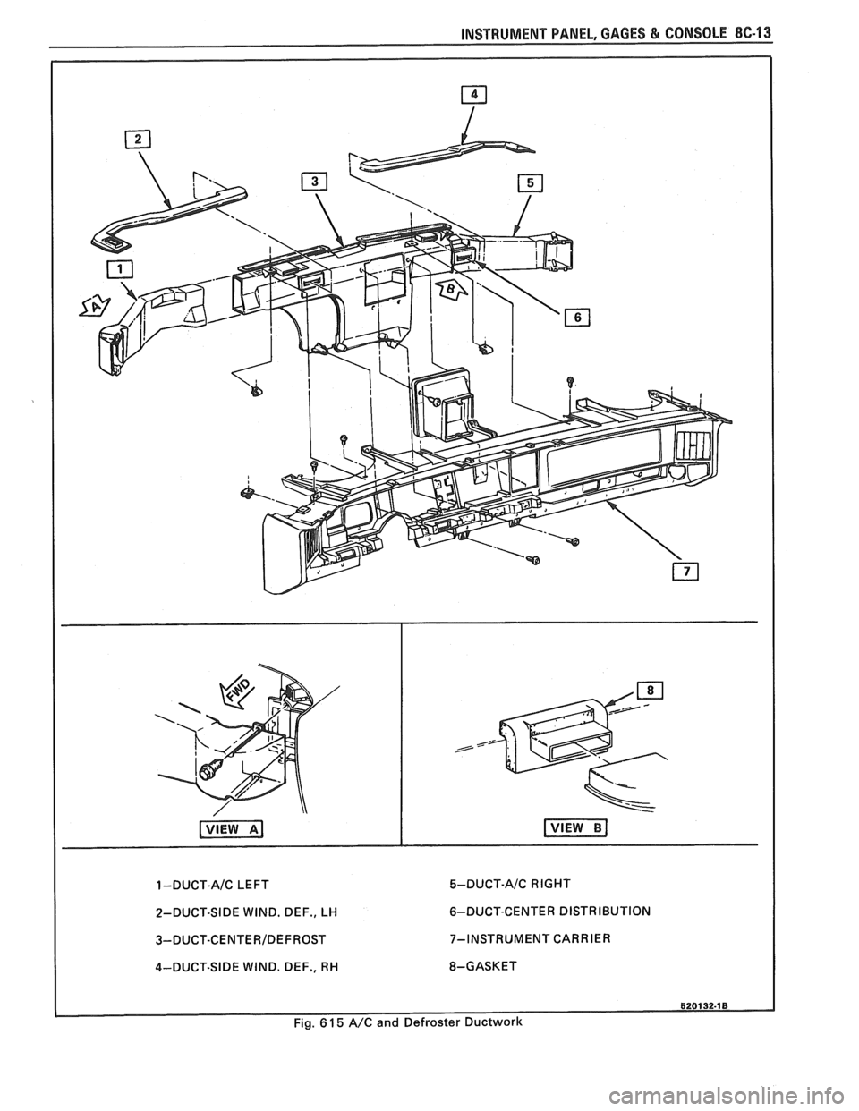
1 -DUCT-A/C LEFT
2-DUCT-SIDE WIND. DEF., LH
3-DUCT-CENTERIDEF ROST
4-DUCT-SIDE WIND. DEF., RH
5-DUCT-A/C RIGHT
6-DUCT-CENTER DISTRIBUTION
7-INSTRUMENT CARRIER
8-GASKET
Page 1625 of 1825
8C14 INSTRUMENT PANEL, GAGES & CONSOLE
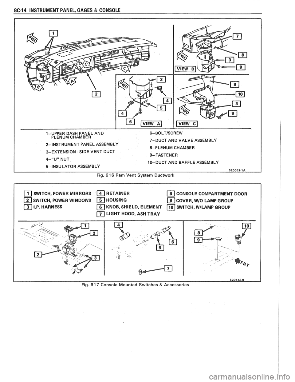
1-UPPER DASH PANEL AND 6-BOLTISCREW
PLENUM CHAMBER
7-DUCT AND VALVE ASSEMBLY
2-INSTRUMENT PANEL ASSEMBLY
8-PLENUM CHAMBER
3-EXTENSION
- SIDE VENT DUCT
4-"U" NUT
10-DUCT AND BAFFLE ASSEMBLY
Fig.
6 16 Ram Vent System Ductwork
SWITCH, POWER MIRRORS RETAINER a CONSOLE COMPARTMENT DOOR
SWITCH, POWER WINDOWS HOUSING
COVER, W/O LAMP GROUP
I.P. HARNESS
KNOB, SHIELD, ELEMENT SWITCH, \MILAMP GROUP
LIGHT HOOD, ASH TRAY
Fig. 6 17 Console Mounted Switches & Accessories
Page 1626 of 1825
INSTRUMENT PANEL, GAGES & CONSOLE 8C-15
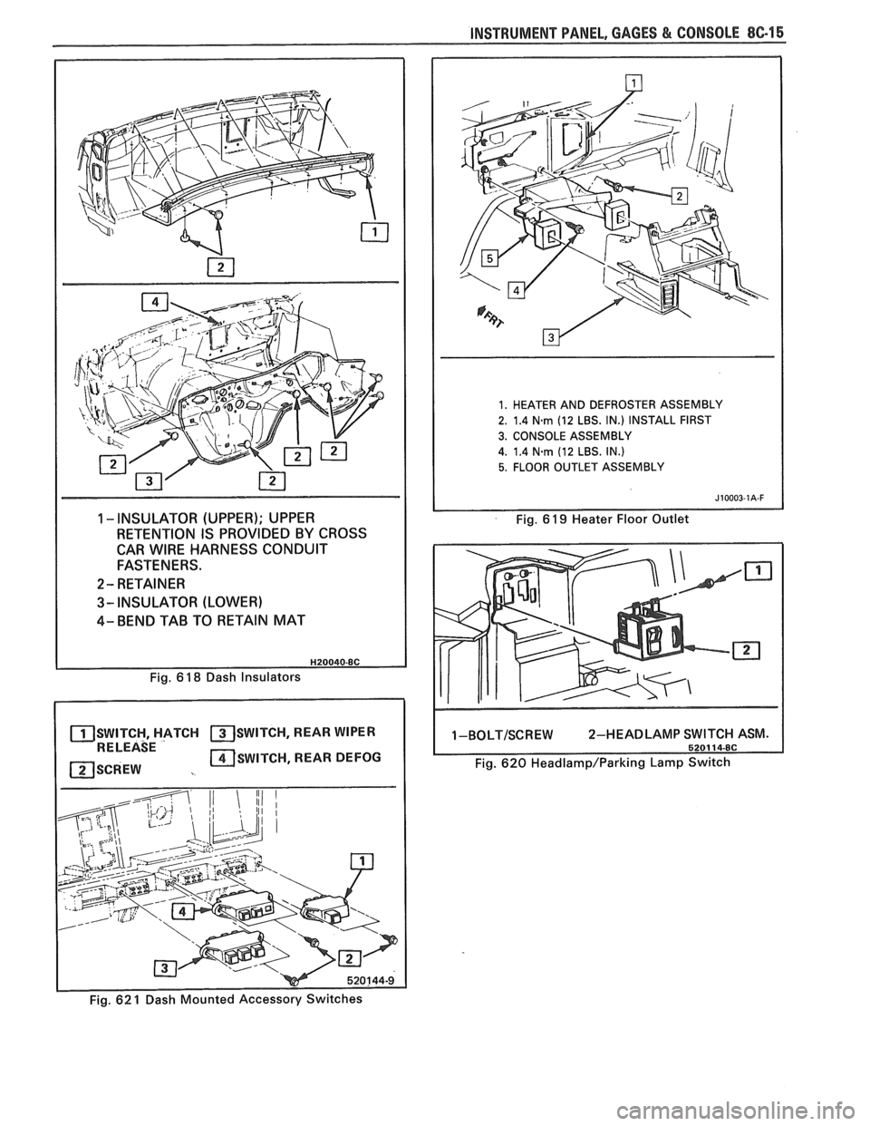
1 -INSULATOR (UPPER); UPPER
RETENTION IS PROVIDED BY CROSS
CAR
WIRE HARNESS CONDUIT
FASTENERS.
2- RETAINER
3- INSULATOR (LOWER)
4- BEND TAB TO RETAIN MAT
1. HEATER AND DEFROSTER ASSEMBLY
2. 1.4
N-rn (12 LBS. IN.) INSTALL FIRST
3. CONSOLE ASSEMBLY
4. 1.4
Narn (12 LBS. IN.)
5. FLOOR OUTLET ASSEMBLY
Fig. 6 19 Heater Floor Outlet
Fig. 6
18 Dash Insulators
SWITCH, HATCH SWITCH, REAR WIPER RELEASE
SCREW SWITCH, REAR DEFOG
1-BOLT/SCREW 2-HEADLAMP
Fig. 620 Headlamp/Parking Lamp Switch
- Fig. 62 1 Dash Mounted Accessory Switches
Page 1627 of 1825

Page 1628 of 1825
WINDSI4IELD WIPER SYSTEMS - F CARLINE 8E -1
SECTION 8E
F CARL
ELD W PER-WASHER SYSTEM
PULSE & STANDARD
CONTENTS
General Description ....................... 8E -1 Park Switch Replacement ............... .8E -3
Wiper and Washer Operation
............ 8E -1
Wiper Motor Replacement .............. 8E -1 1
Pulse Windshield Wiper System
........... 8E -1
Wiper Transmission .................... 8E -1 1
Diagnosis Wiper Arm
........................... 8E -12
Diagnostic Procedures
................... 8E -2 Wiper Blade ........................... 8E -13
Wiper Motor
........................... 8E -2 Wiper Blade Insert ..................... 8E -14
Washer Pump
.......................... 8E -2 Windshield Washer ..................... 8E -15
........................ Diagnostic Chart 8E -3 Unit Repair
On-Car Service Gear Replacement
..................... 8E - 15
Washer Pump Replacement .............. 8E -3 Wiper-Washer Nozzle and Container
Wiper Cover Replacement
............... 8E -3 Mounting ........................... 8E -1 8
GENERAL DESCRIPTION
Figs. hand 2
The Permanent Magnet (PM) Depressed Park
windshield
(w/s) wiper with remote washer pump sys-
tem consists of a depressed park wiper motor and a
remote washer pump mounted on the washer fluid
container.
Based on the type of control switch used and
whether an optional electronic printed circuit board is
attached in the wiper cover, the system can serve as
either a pulse type wiper-washer system or a standard
type windshield wiper. Pulse timing and "demand"
wash functions are controlled electronically on pulse
windshield wipers.
WIPER AND WSHER OPERAflON
Pulse Windshield Wiper System Fig. 1 Wiper Motor
Electronic logic circuits on a pulse wiper system's
printed circuit board establish all timing and washer
commands. When the WASH switch is pressed, the
washer sprays only during the wiper arm
outwipe and
pulsates operation for 2-1/2 seconds. Then the wiper
dry wipes for nearly
6 seconds before shutting off. See
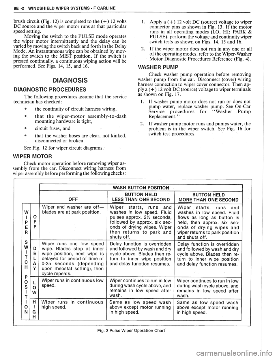
Pulse Wiper Operation Chart, Fig.
3, for a brief de-
scription of pulse wiper system operation.
If the WASH switch is pressed for more than one
second, a (demand) wash is performed for as long as
the switch is depressed. This wash action is followed by
6 seconds of dry wipes before shut-off. With the control
switch in the
LO or HI speed position, the respective
Fig. 2 Wiper-Washer Control Switch
Page 1629 of 1825
8E -2 WINDSHIELD WIPER SYSTEMS F CARLINE
brush circuit (Fig. 12) is completed to the (+) 12 volts
DC source and the wiper motor runs at that particular
speed setting.
Moving the switch to the PULSE mode operates
the wiper motor intermittently and the delay can be
varied by moving the switch back and forth in the Delay
Mode. An instantaneous wipe can be obtained by mov-
ing the switch to the MIST position. If the switch is
pressed continually, a continuous wiping action will be
performed. See Figs. 14,
15, and 16.
DIAGNOSVC PROCEDURES
The following procedures assume that the service
technician has checked:
@ the continuity of circuit harness wiring,
@ that the wiper-motor assembly-to-dash
mounting hardware is tight,
circuit fuses, and
@ that the washer hoses are clear, not kinked,
disconnected or broken.
1. Apply a (+) 12 volt DC (source) voltage to wiper
connector pins as shown in Fig. 13. If the motor
runs in all operating modes
(LO, HI; PARK &
PULSE), perform the voltage and continuity wiper
switch tests as shown on Figs. 14, 15 and 16.
2. If the wiper motor does not run in any one or all
of the operating modes, refer to the Wiper-Washer
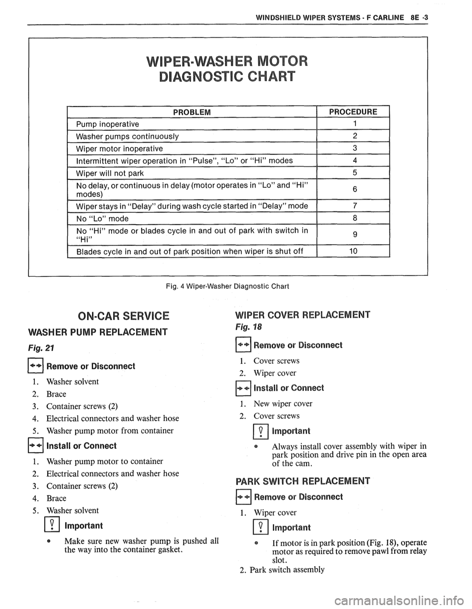
Motor Diagnostic Procedures Reference (Fig.
4).
WASHER PUMP
Check washer pump operation before removing
washer pump from the car. Disconnect (cover) wiring
harness connection to wiper cover connector. Then ap-
ply a
(+) 12 volt DC (source) voltage to wiper terminals
as shown on Fig. 17.
1. If washer pump motor does not run or does not
pump water, replace washer pump, See On-Car
Service procedures for "Washer Pump
Replacement.
' '
2. If washer pump motor runs and pumps water, the
problem is in the wiper switch. See Fig. 16 for
switch test procedures.
See Fig. 12 for wiper circuit diagrams.
WIPER MOTOR
Check motor operation before removing wiper as-
sembly from the car. Disconnect wiring harness from
wiper assembly before performing the following checks:
Fig. 3 Pulse Wiper Operation Chart
Page 1630 of 1825
WINDSHIELD WIPER SYSTEMS - F CARLINE 8E -3
WIPER-WASHER MOTOR
DIAGNOSTIC CHART
Fig. 4 Wiper-Washer Diagnostic Chart
ON-CAR SERVICE WIPER COVER REPLACEMENT
VVASHER PUMP REPLACEMENT Fig. 18
Fig. 21 Remove or Disconnect
Remove or Disconnect
1. Washer solvent
2. Brace
1. Cover screws
2. Wiper cover
Install sr Connect
3. Container screws (2) 1. New wiper cover
4. Electrical connectors and washer hose 2.
Cover screws
5. Washer pump motor from container Important
Install or Connect Always install cover assembly with wiper in
park position and drive pin in the open area
1. Washer pump motor to container of the cam.
2. Electrical connectors and washer hose
3. Container screws (2)
4. Brace
PARK SWITCH REPLACEMENT
Remove or Disconnect
Washer solvent 1. Wiper cover
Impo~ant important
@ Make sure new washer pump is pushed all
If motor is in park position (Fig. 18), operate
the way into the container gasket.
rnotor as required to remove pawl from relay
slot.
2. Park switch assembly