PONTIAC FIERO 1988 Service Repair Manual
Manufacturer: PONTIAC, Model Year: 1988, Model line: FIERO, Model: PONTIAC FIERO 1988Pages: 1825, PDF Size: 99.44 MB
Page 1671 of 1825
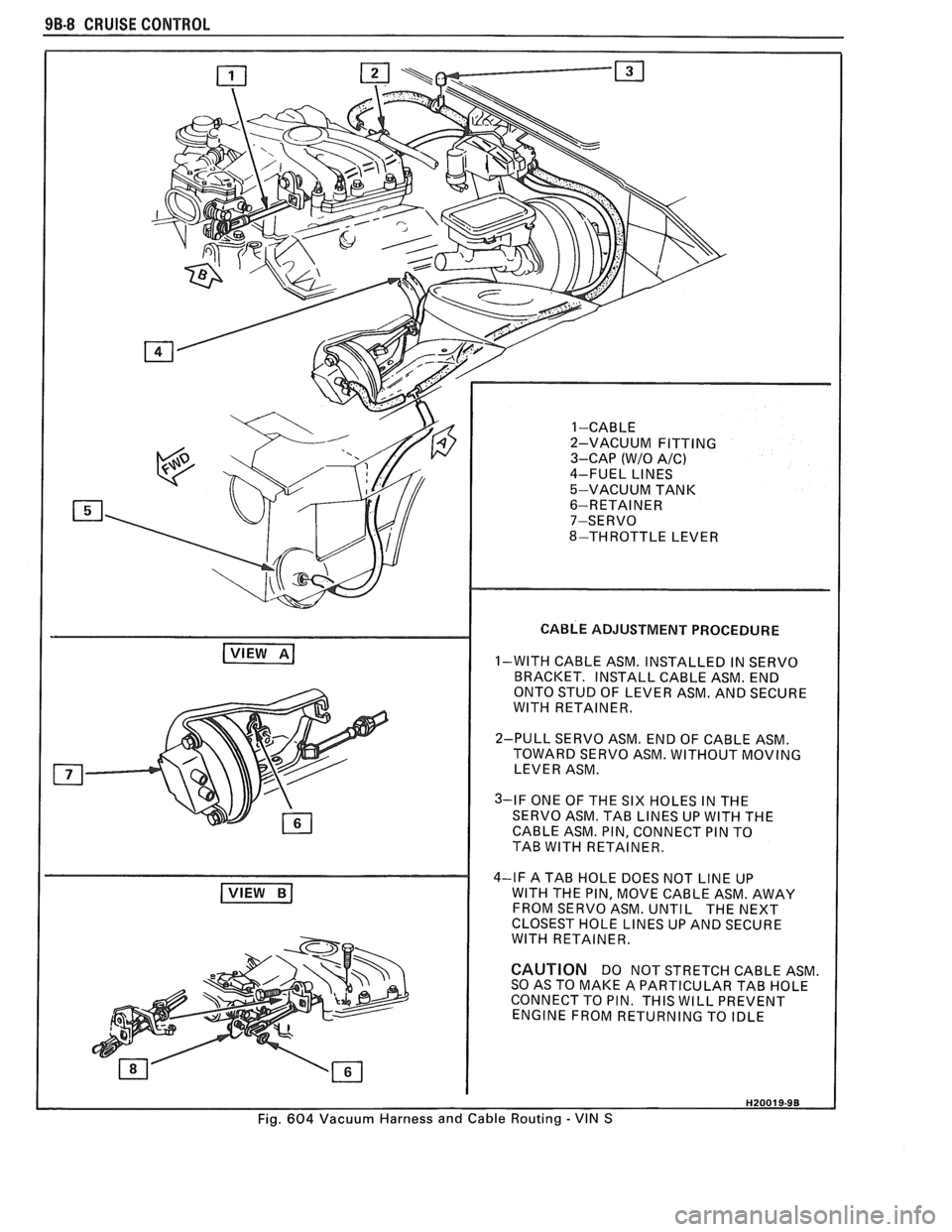
9B-8 CRUISE CONTROL
( VIEW BI
CABLE ADJUSTMENT PROCEDURE
1-WITH CABLE ASM. INSTALLED IN SERVO
BRACKET. INSTALL CABLE ASM. END
ONTO STUD OF LEVER ASM. AND SECURE
WlTH RETAINER.
2-PULL SERVO ASM. END OF CABLE ASM.
TOWARD SERVO ASM. WITHOUT MOVING
LEVER ASM.
3-IF ONE OF THE SIX HOLES IN THE
SERVO ASM. TAB LINES UP WlTH THE
CABLE ASM. PIN, CONNECT PIN TO
TAB WlTH RETAINER.
4-IF A TAB HOLE DOES NOT LINE UP
WlTH THE PIN, MOVE CABLE ASM. AWAY
FROM SERVO ASM. UNTIL THE NEXT
CLOSEST HOLE LINES UP AND SECURE
WlTH RETAINER.
CAUTION DO NOT STRETCH CABLE ASM
SO AS TO MAKE A PARTICULAR TAB HOLE
CONNECT TO PIN. THIS WILL PREVENT
ENGINE FROM RETURNING TO IDLE
Fig. 604 Vacuum Harness and Cable Routing - VIN S
Page 1672 of 1825
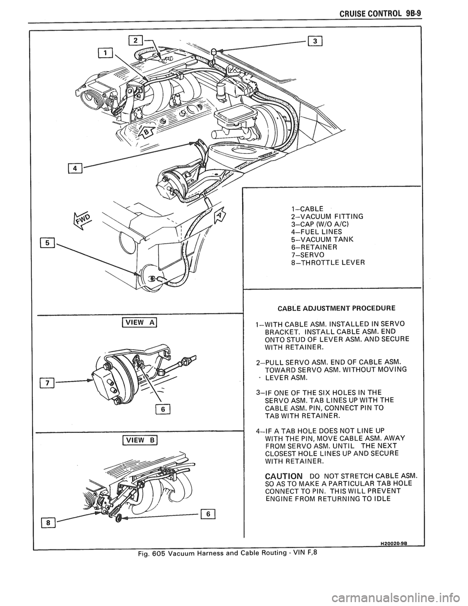
CABLE ADJUSTMENT PROCEDURE
1-WITH CABLE ASM. INSTALLED IN SERVO
BRACKET. INSTALL CABLE ASM. END
ONTO STUD OF LEVER ASM. AND SECURE
WlTH RETAINER.
2-PULL SERVO ASM. END OF CABLE ASM.
TOWARD SERVO ASM. WITHOUT MOVING
LEVER ASM.
3-IF ONE OF THE SIX HOLES IN THE
SERVO ASM. TAB LINES UP WlTH THE
CABLE ASM. PIN, CONNECT PIN TO
TAB WITH RETAINER.
4-IF A TAB HOLE DOES NOT
LINE UP
WITH THE PIN, MOVE CABLE ASM. AWAY
FROM SERVO ASM.
UNTl L THE NEXT
CLOSEST HOLE LINES UP AND SECURE
WlTH RETAINER.
CAUTION DO NOT STRETCH CABLE ASM.
SO AS TO MAKE A PARTICULAR TAB HOLE
CONNECT TO PIN. THIS WILL PREVENT
ENGINE FROM RETURNING TO IDLE
Page 1673 of 1825
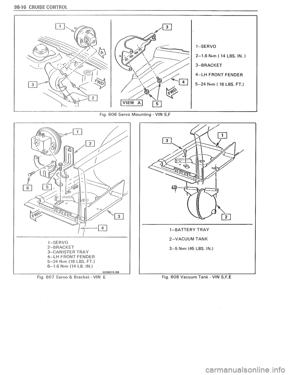
9B-10 CRUISE CONTROL
1-SERVO
2-1.6
Nem ( 14 LBS. IN. )
3-BRACKET
4-LH FRONT FENDER
5-24
Nom ( 18 LBS. FT.)
Fig. 606 Servo Mounting - VlN S,F
I -SE RVO 2-BRACI
4-LH FRONT FENDER
5-24 Nom (18 LBS. FT.)
6-1.6 Nm (14 LB. IN.)
Fig. 607 Servo &I Bracket - VIN E
1 -BATTERY TRAY
2-VACUUM TANK
I 3-5 Nem (45 LBS. IN.)
Fig. 608 Vacuum Tank - VIN S,F,E
Page 1674 of 1825
MISCELLANEOUS ACCESSORIES 96-4
SCELLANEOUS ACCESSOR
General Description ................................. 9G-1
Rally Gages .................................................. 9G- 1
Tachometer ................................................. 9G- 1
Trip Odometer
............................................. 9G- 1
Electric Rear Window Defogger ................. 9G-2
Power Remote Control Rearview
Mirror ........................................................ 9G-2
Diagnosis .................................................... 9G-2
Rally Gages ............................................... 9G-2
Tachometer .................................... .... .... 9G-2
Electric Rear Window Defogger ................. 9G-2
Power Remote Control Rearview
Mirror ........................................................ 96-2
Dash and Console Mounted
Accessory Switches
................................. 9G-4
General Description .................................. 9G-4
Electronic Glare Control Mirror ................. 9G-4
On-Car Service ............................................. 9G-4
Rally Gages, Tach ....................................... 96-4.
Rear Window Defogger ............................ 96-4.
Power Remote Control Mirror .................... 9G-4
GENERAL BESCRIP"T0N
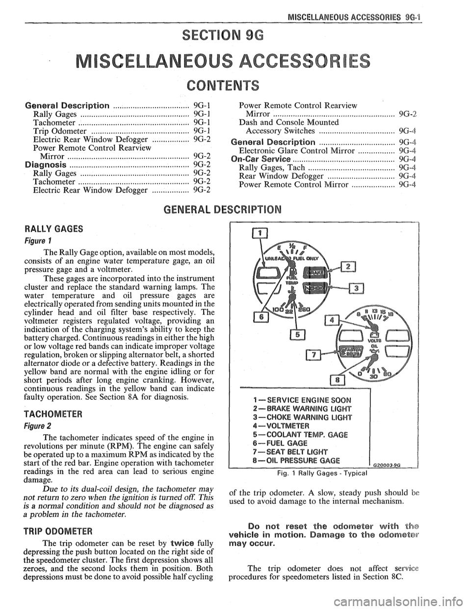
RALLY GAGES
Figure I
The Rally Gage option, available on most models,
consists of an engine water temperature gage, an oil
pressure gage and a voltmeter.
These gages are incorporated into the instrument
cluster and replace the standard warning lamps. The
water temperature and oil pressure gages are
electrically operated from sending units mounted in the
cylinder head and oil filter base respectively. The
voltmeter registers regulated voltage, providing an
indication of the charging system's ability to keep the
battery charged. Continuous readings in either the high
or low voltage red bands can indicate improper voltage
regulation, broken or slipping alternator belt,
a shorted
alternator diode
or a defective battery. Readings in the
yellow band are normal with the engine idling or for
short periods after long engine cranking. However,
continuous readings in the yellow band can indicate
faulty operation. See Section
8A for diagnosis.
TACHOMETER
Figure 2
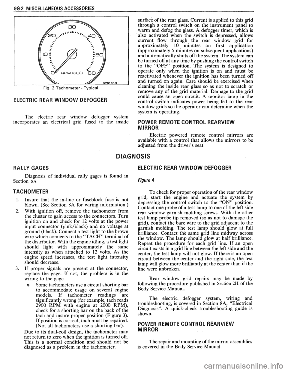
The tachometer indicates speed of the engine in
revolutions per minute (RPM). The engine can safely
be operated up to a maximum RPM as indicated by the
start of the red bar. Engine operation with tachometer
readings in the red area can lead to serious engine
damage.
Due to its dual-coil design, the tachometer may
not return to zero when the ignition
is turned oft: This
is
a normal condition and should not be diagnosed as
a problem in the tachometer.
TRIP ODOMETER
The trip odometer can be reset by twice fully
depressing the push button located on the right side of
the speedometer cluster. The first depression shows all
zeroes, and the second locks them in position. Both
depressions must be done to avoid possible half cycling
I -SERVICE ENGINE SOON
2-BRAKE WARNING LIGHT
3-CHOKE WARNING LIGHT
4-VOLTMETER
5-COOUNT TEMP. GAGE
6-FUEL GAGE
7-SEAT BELT LIGHT
8-OIL PRESSURE GAGE G20003 9G
Fig. 1 Rally Gages - Typical
of the trip odometer. A slow, steady push should be
used to avoid damage to the internal mechanism.
Do not reset the odometer with the
vehicle in motion. Damage to the odometer
may occur.
The trip odometer does not affect service
procedures for speedometers listed in Section
8C.
Page 1675 of 1825
9G-2 MISCELLANEOUS ACCESSORIES
Fig. 2 Tachometer - Typical
RPMX I00 €31-
ELECTRIC REAR WINDOW DEFOGGER
surface of the rear glass. Current is applied to this grid
through a control switch on the instrument panel to
warm and defog the glass. A defogger timer, which is
also activated when the switch is depressed, allows
current flow through the rear window grid
for
approximately 10 minutes on first application
(approximately
5 minutes on subsequent applications)
and automatically shuts off the system. The system can
be turned off at any time by pushing the control switch
to the "OFF" position. The system is designed to
operate only when the ignition is on and must be
reactivated whenever the ignition has been turned off
and turned on again. Care should be exercised when
cleaning the inside rear glass so as not to scratch or
remove any of the grid material. Damage to the grid
could cause an open circuit. A monitor lamp in-the
control switch indicates power being fed to the rear
window grids so the operator can determine when the
system is operating.
The electric rear window defogger system
incorporates an electrical grid fused to the inside
POWER REMOTE CONTROL REARVIEW
MIRROR
Electric powered remote control mirrors are
available with a control that allows the mirrors to be
adjusted from the driver's seat.
RALLY GAGES ELECTRIC REAR WINDOW DEFOGGER
Diagnosis of individual rally gages is found in
Section
8A Figure 4
TACHOMETER To check for moper o~eration of the rear window
1. Insure that the in-line or fuseblock fuse is not
blown. (See Section 8A for wiring information.)
2. With ignition off, remove the tachometer from
the cluster to gain access to the connectors. Turn
ignition on and check for
12 volts at the power
input connector
(pink/black) and no voltage at
ground (black). Connect a test light to the brown
wire which connects to the "TACH" terminal of
the distributor. With the engine idling, a test light
should light with approximately the same
intensity as when attached to
12 volts. As the
engine speed increases, the test light intensity
should decrease.
3. If proper signals are present at the connector,
replace the gage. If not, the problem is in the
wiring to the gage.
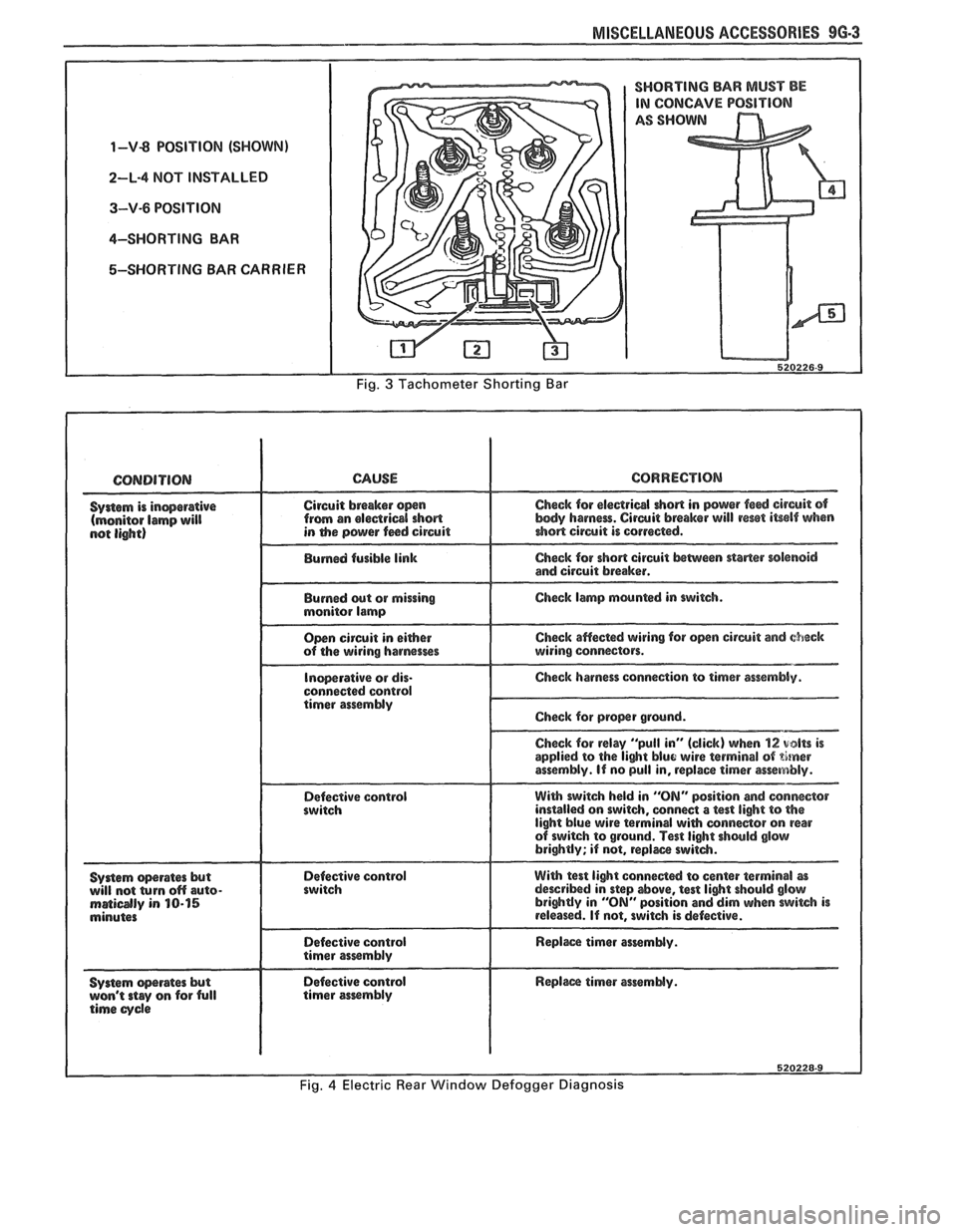
Some tachometers use a circuit shorting bar
to accommodate usage on several engine
models. If tachometer readings are
significantly wrong (for example, tach reads
2900 RPM with engine at 2000 RPM),
check for a shorting bar on the back of the
tach and insure proper position (Figure
3).
If position is correct, tach must be repaired.
(Not all tachometers use a shorting bar).
Due to its dual-coil design, the tachometer
may
- grid, start the engine a& actuate the system by
depressing the control switch to the
"ON" position.
Contact one probe of a test lamp to one of the left side
rear window garnish molding screws. With the other
test lamp probe tip removed (so as not to damage the
grid), contact the bare wire to the grid adjacent to the
garnish molding. The test lamp should glow at full
brilliance. Contact the same grid line midway across
the window. The lamp should glow at half brilliance.
Repeat the procedure for each grid line. If an open
circuit exists in a grid line between the left side and the
center, the test lamp will not glow. If there is an open
circuit between the center and the right side, the test
lamp will glow more brilliantly at the center than if the
line were unbroken.
Rear window grid repairs may be made by
following the procedure published in
Section 2H of the
Body Service Manual.
The electric defogger system, wiring and
troubleshooting, is covered in Section
8A, "Electrical
Diagnosis". A quick-check troubleshooting guide is
shown.
POWER REMOTE CONTROL REARVIEW
MIRROR
not return to zero when tvhe ignition is turned off'.
This is a normal condition and should not be The
repair and mounting of the mirror assemblies
diagnosed as a problem in the tachometer. is
covered in the Body Service Manual.
Page 1676 of 1825
MISCELLANEOUS ACCESSORIES 96-3
1-V-8 POSITION (SHOWN)
2-L-4 NOT INSTALLED
3-V-6 POSITION
4-SHORTING BAR
5-SHORTING BAR CARRIER
I SHORTING BAR MUST BE
CONCAVE POSITION
SHO
520226-9
Fig. 3 Tachometer Shorting Bar
Syrlem operates but Defective control will not (urn off auto- maidly in 10-15 minutes
System
-rates but Defective control Replm timer essemMy. won't stay on for full timer assmbly time cycle
Page 1677 of 1825
96.4 MISCELLANEOUS ACCESSORIES
DASH AND CONSOLE MOUNTED ACCESSORY
SWITCHES
Installation for various dash and console
mounted accessory switches is shown in Section
8C.
GENERAL DESCRIPIIOM
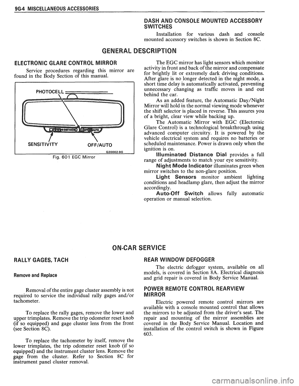
ELECTRONIC GLARE CONTROL MIRROR
Service procedures regarding this mirror are
found in the Body Section of this manual.
Fig. 601 EGC Mirror
The EGC mirror has light sensors which monitor
activity in front and back of the mirror and compensate
for brightly lit or extremely dark driving conditions.
After glare is no longer detected in the night mode, a
short time delay is automatically activated, preventing
unnecessary changing as traffic moves in and out
behind the car.
As an added feature, the Automatic
Day/Night
Mirror will hold in the normal viewing mode whenever
the shift selector is placed in reverse. This assures you
of a bright, clear view while backing up.
The Automatic Mirror with EGC (Electornic
Glare Control) is a technological breakthrough using
advanced computer circuitry. It is powered by the
vehicle electrical system and requires no batteries or
scheduled maintenance. Power is drawn only when the
ignition is on.
Illuminated Distance Dial provides a full
range of adjustments to match your eye sensitivity.
Night Mode Indicator illuminates green when
mirror switches to the non-glare position.
Light Sensors monitor ambient lighting
conditions and
headlamp glare, then adjust the mirror
accordingly.
Auto-Off Switch allows fully automatic
operation or manual selection.
ON-CAR SERVICE
RALLY GAGES, TACH REAR WINDOW DEFOGGER
Remove
and Replace
The electric defogger system, available on all
models, is covered in Section
8A. Electrical diagnosis
and grid repair is covered in Body Service Manual.
Removal of the entire gage cluster assembly is not
POWER RmOTE CONTROL REARVIEW
required to service the individual rally gages and/or MIRROR
tachometer.
Electric powered remote control mirrors are
available with a console mounted control that allows
To replace the rally gages, remove the lower and the
mirrors to be adjusted from the driver's seat. The
upper trimplates. Remove the trip odometer reset knob repair
and mounting of the mirror assemblies are
(if so equipped) and gage cluster lens from the front covered in
the Body Service Manual. Location and
(see Section
8C). installation of the control switch is shown in Figure
603.
To replace the tachometer by itself, remove the
lower trimplates, the trip odometer reset knob (if so
equipped) and the instrument cluster lens. Remove the
gage from the cluster. Refer to Section
8C for
hstrument panel cluster removal.
Page 1678 of 1825
MISCELLANEOUS ACCESSORIES 9G-5
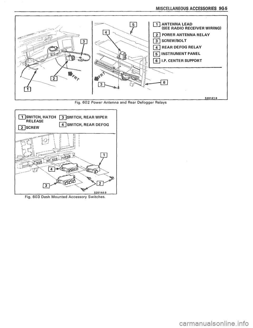
ANTENNA LEAD
(SEE RADIO RECEIVER WIRING)
POWER ANTENNA RELAY
SCREWIBOLT
REARD DEFOG RELAY
INSTRUMENT PANEL
11 I.P. CENTER SUPPORT XJ I
Fig. 602 Powe: Antenna and Rear Defogger Relays
SWITCH, HATCH SWITCH, REAR WIPER 1 RELEASE - I ~SWITCW, REAR BEFOG
I
1 520144-9
Fig. 603 Dash Mounted Accessory Switches.
Page 1679 of 1825

Page 1680 of 1825
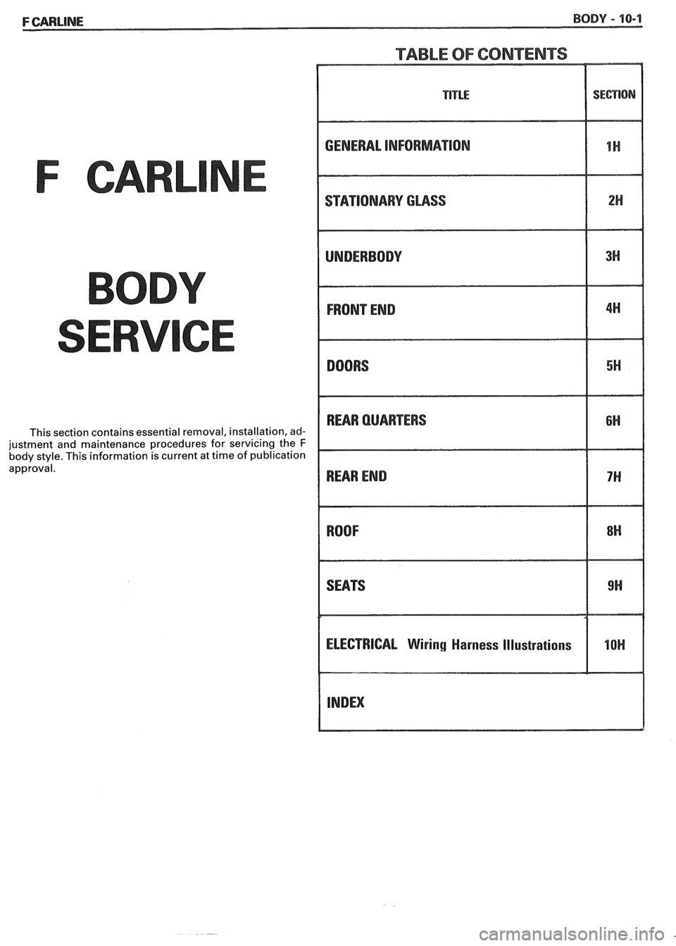
TABLE OF CONTENTS
F CARL
This section contains essential removal, installation, ad-
justment and maintenance procedures for servicing the
F body style. This information is current at time of publication
approval.
GENERAL INFORMATION
STATlONARV GLASS
REAR QUARTERS
ELECTRICAL
Wiring Harness Illustrations
I -IoH I