PONTIAC FIERO 1988 Service Repair Manual
Manufacturer: PONTIAC, Model Year: 1988, Model line: FIERO, Model: PONTIAC FIERO 1988Pages: 1825, PDF Size: 99.44 MB
Page 1661 of 1825
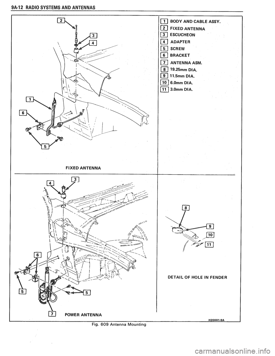
9A-12 RADIO SYSTEMS AND ANENNAS
FIXED ANTENNA
POWER ANTENNA DETAIL OF
HOLE IN FENDER
Fig. 609 Antenna Mounting
Page 1662 of 1825
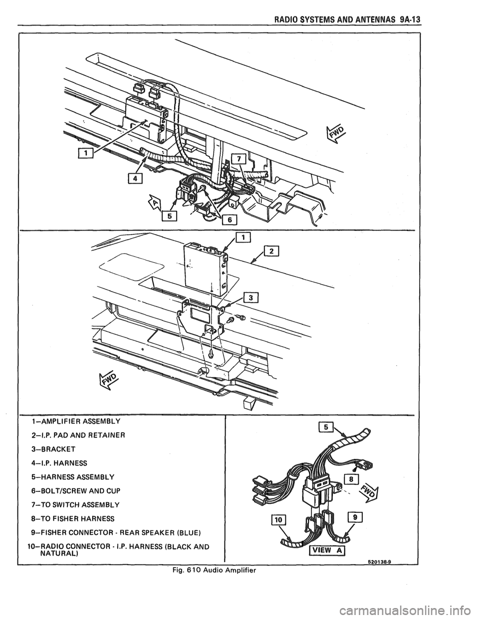
RADIO SYSTEMS AND ANTENNAS 9A.13
1-AMPLIFIER ASSEMBLY
2-I.P. PAD AND RETAINER
3-BRACKET
4-I.P. HARNESS 5-HARNESS ASSEMBLY
6-BOLTISCREW AND CUP
7-TO SWITCH ASSEMBLY
8-TO FISHER HARNESS
9-FISHER CONNECTOR
- REAR SPEAKER (BLUE)
10-RADIO CONNECTOR
- I.P. HARNESS (BLACK AND
NATURAL)
Fig.
6 10 Audio Amplifier
Page 1663 of 1825
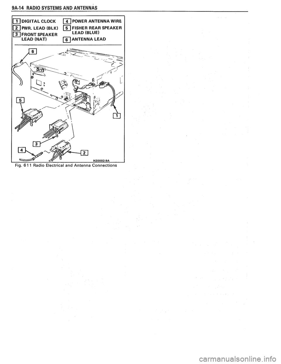
9A-14 RADIO SYSTEMS AND ANTENNAS
DIGITAL CLOCK POWER ANTENNA WIRE
PWR. LEAD (BLK) FISHER REAR SPEAKER
FRONT SPEAKER LEAD (BLUE)
LEAD
(NAT) ANTENNA LEAD
Page 1664 of 1825
CRUISE CONTROL 9B-1
SECTION 9B
SE CONTROL
CONTENTS
General Description ................................... 9B-1
Off/On/Resume/Accel Switch
Operation
................................................ 9B- 1
Set/Coast Button Switch .............................. 9B- 1
Electronic Controller (Module) .................... 9B-2
Servo Unit ..................................................... 9B-2
Speed Sensors ............................................. 9B-3
VSS Buffer Amplifier ................................ 9B-3
PM Generator Speed Signal ..................... 9B-3
Vacuum Supply ............................................. 9B -4
Electrical and Vacuum Release
Switches
..................................................... 9B-4
Electrical Harness ...................................... 9B-4
Diagnosis .................................................. 9B-4
Cruise System Surges .................................... 9B-4
Cruise Set Speed High or Low ..................... 9B-4
Excessive Cruise Speed Loss on Hills .......... 9B-4
Cruise Tap-Up and Tap-Down .................... 9B-4
On-Gar Service (Illustrated) ..................... 9B-6
Cruise Release Switches ............................... 9B-6
............................. Cruise Processor Module 9B-6
Vacuum Harness and Cable Routing -
VIN E ..................................................... 9B-7
Vacuum Harness and Cable Routing -
VIN S ......................................................... 9B-8
Vacuum Harness and Cable Routing -
VIN F,8 ..................................................... 9B-9
Servo Mounting - VIN S,F .......................... 9B-10
....................... Servo and Bracket - VIN E 9B-10
Vacuum Tank - VIN S,F,E ....................... 9B-10
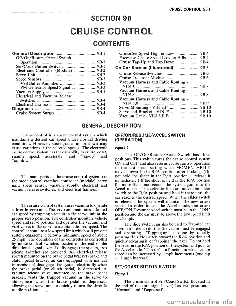
GENERAL DESCRIPTION
Cruise control is a speed control system which
maintains a desired car speed under normal driving
conditions. However, steep grades up or down may
cause variations in the selected speeds. The electronic
cruise control system has the capability to cruise, coast,
resume speed, accelerate, and "tap-up" and
" tap-down" .
The main parts of the cruise control system are
the mode control switches, controller (module), servo
unit, speed sensor, vacuum supply, electrical and
vacuum release switches, and electrical harness.
The cruise control system uses vacuum to operate
a throttle servo unit. The servo unit maintains a desired
car speed by trapping vacuum in the servo unit at the
proper servo position. The controller monitors vehicle
speed and servo position and operates the vacuum and
vent valves in the servo to maintain desired speed. The
controller contains a low speed limit which will prevent
system engagement below a minimum speed of about
25 mph. The operation of the controller is controlled
by mode control switches located in the end of the
directional signal lever. To disengage the system, two
release switches are provided. An electrical release
switch mounted on the brake pedal bracket (brake and
clutch pedal bracket on cars equipped with manual
transmission) disengages the system electrically when
the brake pedal (or clutch pedal) is depressed. A
vacuum release valve, mounted on the brake pedal
bracket, vents the trapped vacuum in the servo to
atmosphere when the brake pedal is depressed,
allowing the servo unit to quickly return the throttle
to idle position.
.
OFF/ON/RESUME/ACCEL SWITCH
(OPERATION)
Figure 1
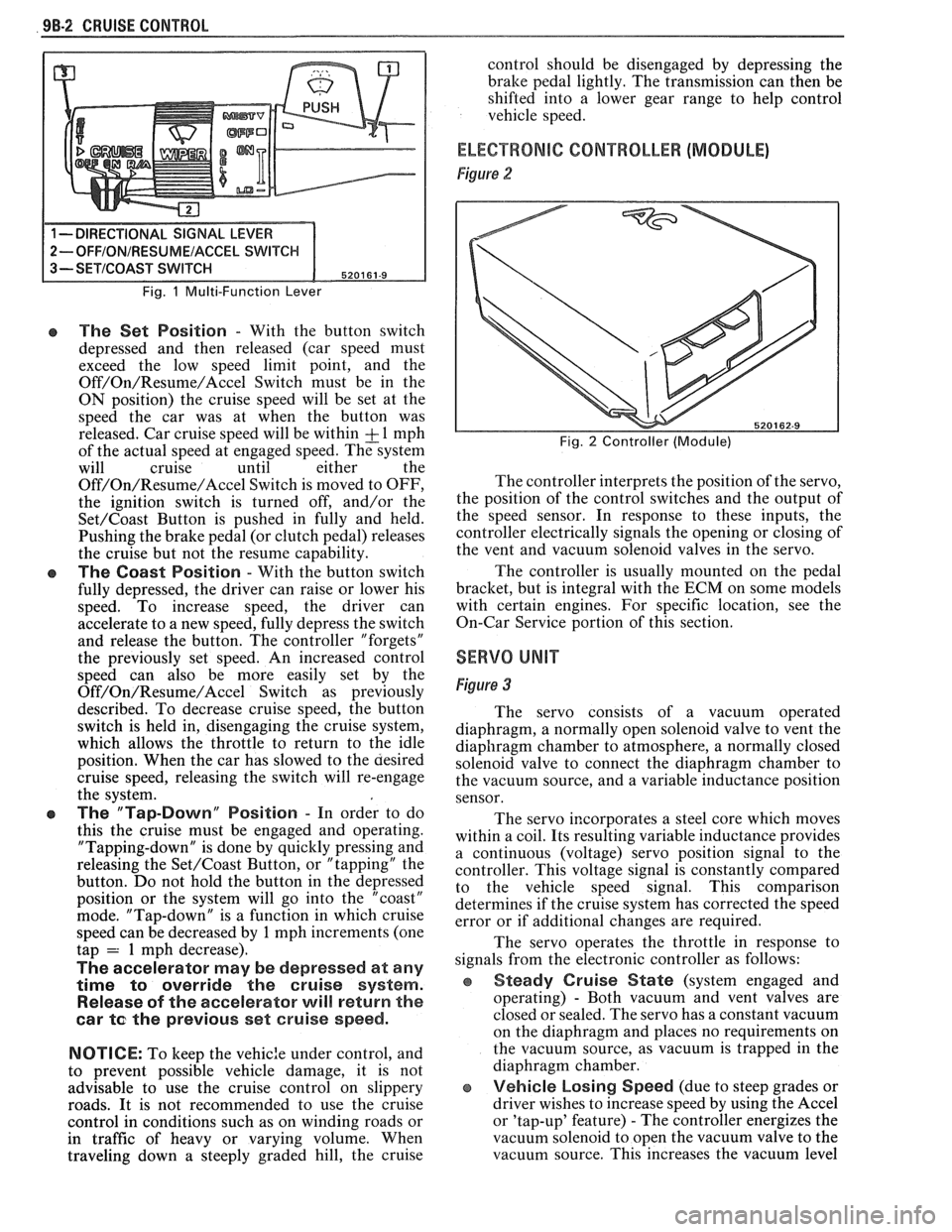
The Off/On/Resume/Accel Switch has three
positions. This switch turns the cruise control system
ON and OFF and also returns cruise control operation
to the last speed setting when MOMENTARILY
moved towards the R/A position after braking. (Do
not hold the slider in the R/A position
... release it
immediately.) If the slider is held in the R/A position
for more than one second, the system goes into the
Accel mode. To accelerate the car, move the slider
switch to the R/A position and hold it there until the
car reaches the desired speed. When the slider switch
is released, the system will maintain the new cruise
speed. In order to use the Accel mode, the cruise
OFF/ON/Resume/Accel switch must be in the "ON"
position and the car must be above the low speed limit
of
25 mph.
The slide switch can also be used to "tap-up" car
speed. In order to do this the cruise must be engaged
and operating. "Tapping-up" is done by quickly
pressing the slide switch toward the R/A position and
quickly releasing it, or "tapping" the lever. Do not hold
the lever in the R/A position or the system will go into
the Accel mode. "Tap-up" is a function in which cruise
speed can be increased by
1 mph increments (one tap
= 1 mph increase).
SET/COAST BUTTON SWITCH
Figure 1
The cruise control Set/Coast Switch (located in
the end of the turn signal lever) has two positions
-
"Normal" and "Depressed".
Page 1665 of 1825
98-2 CRUISE CONTROL
Fig. 1 Multi-Function Lever
e The Set Position - With the button switch
depressed and then released (car speed must
exceed the low speed limit point, and the
Off/On/Resume/Accel Switch must be in the
ON position) the cruise speed will be set at the
speed the car was at when the button was
released. Car cruise speed will be within
& 1 mph
of the actual speed at engaged speed. The system
will cruise until either the
Off/On/Resume/Accel Switch is moved to OFF,
the ignition switch is turned off, and/or the
Set/Coast Button is pushed in fully and held.
Pushing the brake pedal (or clutch pedal) releases
the cruise but not the resume capability.
The Coast Position - With the button switch
fully depressed, the driver can raise or lower his
speed. To increase speed, the driver can
accelerate to a new speed, fully depress the switch
and release the button. The controller "forgets"
the previously set speed. An increased control
speed can also be more easily set by the
Off/On/Resume/Accel Switch as previously
described. To decrease cruise speed, the button
switch is held in, disengaging the cruise system,
which allows the throttle to return to the idle
position. When the car has slowed to the aesired
cruise speed, releasing the switch will re-engage
the system.
e The "Tap-Down" Position - In order to do
this the cruise must be engaged and operating.
"Tapping-down" is done by quickly pressing and
releasing the
Set/Coast Button, or "tapping" the
button. Do not hold the button in the depressed
position or the system will go into the "coast"
mode. "Tap-down" is a function in which cruise
speed can be decreased by
1 mph increments (one
tap = 1 mph decrease).
The accelerator may be depressed at any
time
to override the cruise system.
Release of the accelerator will return the
car
te the previous set cruise speed.
NOTICE:
To keep the vehic:e under control, and
to prevent possible vehicle damage, it is not
advisable to use the cruise control on slippery
roads. It is not recommended to use the cruise
control in conditions such as on winding roads or
in traffic of heavy or varying volume. When
traveling down
a steeply graded hill, the cruise control
should be disengaged by depressing the
bralte pedal lightly. The transmission can then be
shifted into a lower gear range to help control
vehicle speed.
ELECTRONIC CONTROLLER (MODULE)
Figure 2
Fig. 2 Controller (Module)
The controller interprets the position of the servo,
the position of the control switches and the output of
the speed sensor. In response to these inputs, the
controller electrically signals the opening or closing of
the vent and vacuum solenoid valves in the servo.
The controller is usually mounted on the pedal
bracket, but is integral with the ECM on some models
with certain engines. For specific location, see the
On-Car Service portion of this section.
SERVO UNIT
Figure 3
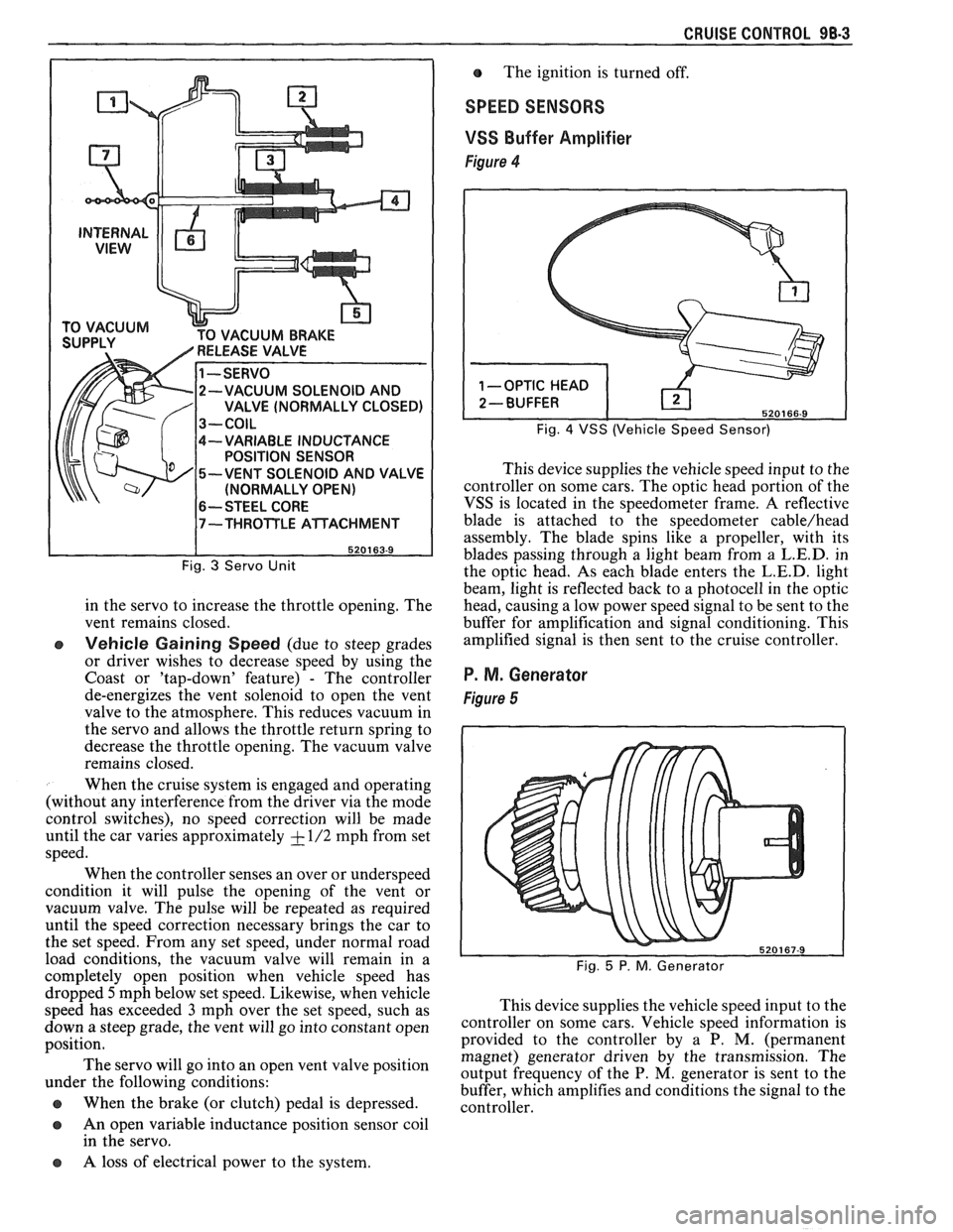
The servo consists of a vacuum operated
diaphragm, a normally open solenoid valve to vent the
diaphragm chamber to atmosphere, a normally closed
solenoid valve to connect the diaphragm chamber to
the vacuum source, and a variable inductance position
sensor.
The servo incorporates a steel core which moves
within a coil. Its resulting variable inductance provides
a continuous (voltage) servo position signal to the
controller. This voltage signal is constantly compared
to the vehicle speed signal. This comparison
determines if the cruise system has corrected the speed
error or if additional changes are required.
The servo operates the throttle in response to
signals from the electronic controller as follows:
Steady Cruise State (system engaged and
operating)
- Both vacuum and vent valves are
closed or sealed. The servo has a constant vacuum
on the diaphragm and places no requirements on
the vacuum source, as vacuum is trapped in the
diaphragm chamber.
e Vehicle Losing Speed (due to steep grades or
driver wishes to increase speed by using the Accel
or 'tap-up' feature)
- The controller energizes the
vacuum solenoid to open the vacuum valve to the
vacuum source. This increases the vacuum level
Page 1666 of 1825
CRUISE CONTROL 98-3
CUUM BRAKE
-VARIABLE INDUCTANCE
POSITION SENSOR
-VENT SOLENOID AND VALVE
(NORMALLY OPEN)
6-- STEEL CORE
Fig. 3 Servo Unit
in the servo to increase the throttle opening. The
vent remains closed.
e Vehicle Gaining Speed (due to steep grades
or driver wishes to decrease speed by using the
Coast or 'tap-down' feature)
- The controller
de-energizes the vent solenoid to open the vent
valve to the atmosphere. This reduces vacuum in
the servo and allows the throttle return spring to
decrease the throttle opening. The vacuum valve
remains closed.
When the cruise system is engaged and operating
(without any interference from the driver via the mode
control switches), no speed correction will be made
until the car varies approximately
+ - 1/2 mph from set
speed.
When the controller senses an over or underspeed
condition it will pulse the opening of the vent or
vacuum valve. The pulse will be repeated as required
until the speed correction necessary brings the car to
the set speed. From any set speed, under normal road
load conditions, the vacuum valve will remain in a
completely open position when vehicle speed has The
ignition is turned off.
SPEED SENSORS
VSS
Buffer Amplifier
Figure 4
Fig. 4 VSS (Vehicle Speed Sensor)
This device supplies the vehicle speed input to the
controller on some cars. The optic head portion of the
VSS is located in the speedometer frame. A reflective
blade is attached to the speedometer
cable/head
assembly. The blade spins like a propeller, with its
blades passing through a light beam from a
L.E.D. in
the optic head. As each blade enters the
L.E.D. light
beam, light is reflected back to a photocell in the optic
head, causing a low power speed signal to be sent to the
buffer for amplification and signal conditioning. This
amplified signal is then sent to the cruise controller.
P. M. Generator
Figure 5
dropped 5mph below set speed. Likewise, when vehicle
speed has exceeded
3 mph over the set speed, such as This
device supplies the vehicle speed input to the
down a steep grade, the vent will go into ,-onstant open ~0ntI-011er on some cars. Vehicle speed information is
position. provided
to the controller by a P. M. (permanent
magnet) generator driven by the transmission. The
The servo go into an 'Pen vent position output frequency of the P. M, generator is sent to the under the following conditions:
buffer, which amplifies and conditions the signal to the
@ When the brake (or clutch) pedal is depressed. controller.
a An open variable inductance position sensor coil
in the servo.
a A loss of electrical power to the system.
Page 1667 of 1825
VACUUM SUPPLY
Tht vacuum to operate the Cruise Control servo
can come from: manifold vacuum connected straight
to the servo, from manifold through a vacuum storage
tank, or straight from a vacuum pump. For specific
vacuum routing, see On-Car Service.
ELECTRICAL AND VACUUM RELEASE
SWITCHES
These switches are used to disengage the cruise
control system. An electrical release switch mounted
on the brake pedal bracket (and clutch pedal bracket
on cars equipped with manual transaxle) disengages
the system electrically when the brake (or clutch) pedal is
depressed. This is done by interrupting the flow of
current to the controller. A vacuum release valve
mounted on the brake pedal bracket vents the trapped
vacuum in the servo to atmosphere when the brake
pedal is depressed, allowing the servo unit to more
quickly return the throttle to idle position. This is done
by routing a separate hose directly to the servo from
the normally closed vacuum switch. These two types
of switches will also sometimes be combined with stop
light switch, TCC switch, or other switches. For
specific usage and adjustment of these switches, see
On-Car Service.
ELECTRICAL HARNESS
For specific wiring and connector locations, see
Section
8A-34, 'Cruise Control'.
Improper operation can be caused by one or a
CRUISE SYSTEM SURGES t combination of mechanical, electrical and vacuum The servo and throttle linkages should operate problems. In resolving any cruise system operating
problem, first make a visual inspection. Check the freely
and smoothly. This linkage should be
system to ensure there are no bare, broken, or adjusted
as described in the On-Car Service
disconnected wires or any pinched, damaged,
-or portion of this section.
disconnected vacuum hoses. The servo and throttle
e Check hose routing for pinches, leaks or
linkage should operate freely and smoothly. The servo restrictions.
(See vacuum schematics in the
linkage should be adjusted as described in the On-Car On-Car
Service portion of this section).
Service portion of this section. See
Section
8A-34, 'Cruise Control'.
CRUISE SET SPEED HIGH OR LOW
Since any problem in this system is either
vacuum, mechanical, or electrical, the technician
should perform a few initial checks before turning to
Section
8A. This can be done by first eliminating a
vacuum or mechanical problem by starting the engine
and using finger to feel for source vacuum at the servo,
and by visual inspection of vacuum release valve,
throttle linkage, vacuum hoses, etc. If preliminary
inspection reveals no solution and the system is
inoperative, use the diagnostic information in Section
8A-34, 'Cruise Control'.
Several versions of a quick check instrument
similar to tool 5-34185 are available. This quick check
instrument is installed in place of the controller and
determines which part of the system has a problem.
Instructions on the operation of the instrument will be
provided with the unit. Check vacuum hoses for
proper routing,
restrictions or leaks. Adjust or replace as
required. (See vacuum schematics in the On-Car
Service portion of this section.)
e Check servo linkage for excess slack and adjust
as described in the On-Car Service portion of this
section.
s If no system problem is noted, replace the
electronic controller (module).
EXCESSIVE CRUISE SPEED LOSS ON HILLS
e Check hoses for vacuum leaks. (See vacuum
schematics in the On-Car Service portion of this
section).
e Determine if check valve is functional (where
applicable).
CRUISE TAP-UP & TAP-DOWN
If all other functions of cruise control are working
except "tap-up" and "tap-down" the controller
(module) is at fault.
Page 1668 of 1825
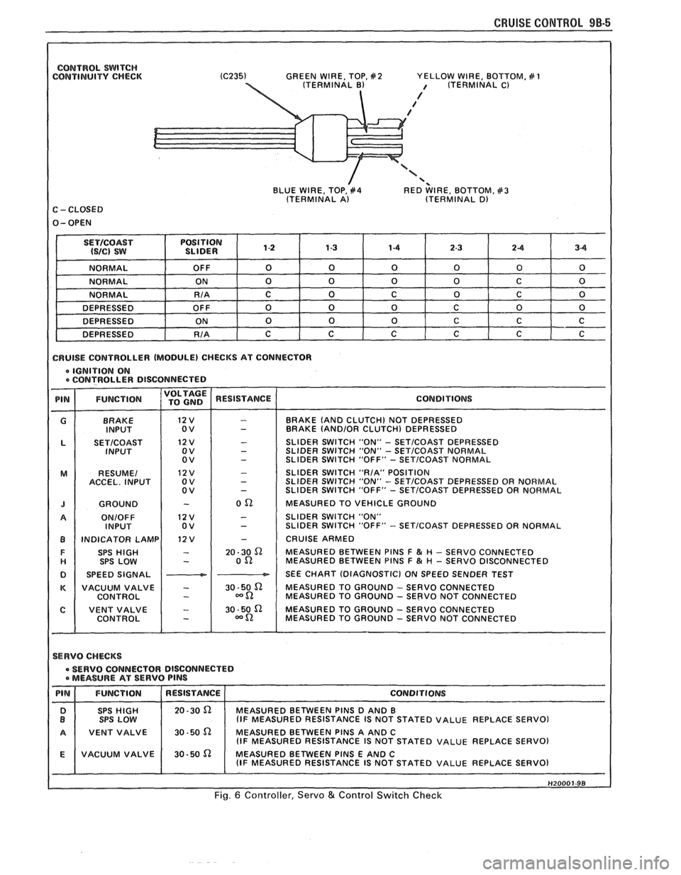
CONTROL SWITCH CONTINUITY CHECK GREEN
WIRE, TOP, #2 YELLOW WIRE, BOTTOM, # 1 / (TERMINAL C)
/ / /
'< BLUE WIRE, TOP, #4 RED WIRE, BOTTOM, #3 (TERMINAL A) (TERMINAL D) C - CLOSED
1 CRUISE CONTROLLER (MODULE) CHECKS AT CONNECTOR
e IGNITION ON e CONTROLLER DISCONNECTE D
BRAKE
INPUT
SETICOAST INPUT
RESUME1
ACCEL. INPUT
GROUND
ONIOFF INPUT
INDICATOR LAMP SPS
HIGH SPS LOW
SPEED SIGNAL
VACUUM VALVE
CONTROL
I
BRAKE (AND CLUTCH) NOT DEPRESSED
BRAKE (AND/OR CLUTCH) DEPRESSED
SLIDER SWITCH "ON"
- SETICOAST DEPRESSED
SLIDER SWITCH "ON" - SET/COAST NORMAL
SLIDER SWITCH "OFF" - SETICOAST NORMAL
SLIDER SWITCH "RIA" POSITION
SLIDER
SWITCH "ON" - SET/COAST DEPRESSED OR NORMAL
SLIDER SWITCH "OFF" - SETICOAST DEPRESSED OR NORMAL
MEASURED TO VEHICLE GROUND
SLIDER SWITCH "ON"
SLIDER SWITCH "OFF"
- SETICOAST DEPRESSED OR NORMAL
CRUISE ARMED
MEASURED BETWEEN PlNS
F & H - SERVO CONNECTED
MEASURED BETWEEN PlNS F & # - SERVO DISCONNECTED
SEE CHART (DIAGNOSTIC) ON SPEED SENDER TEST
MEASURED TO GROUND
- SERVO CONNECTED
MEASURED TO GROUND - SERVO NOT CONNECTED
MEASURED TO GROUND
- SERVO CONNECTED
MEASURED TO GROUND - SERVO NOT CONNECTED
1 SERVO CHECKS
SERVO CONNECTOR DISCONNECTED a MEASURE AT SERVO PlNS
STATED VALUE REPLACE SERVO)
1 A 1 VENT VALVE 1 30-50 n MEASURED BETWEEN PINS A AND C I (IF MEASURED RESISTANCE IS NOT STATED VALUE REPLACE SERVO)
Fig. 6 Controller, Servo & Control Switch Check
Page 1669 of 1825
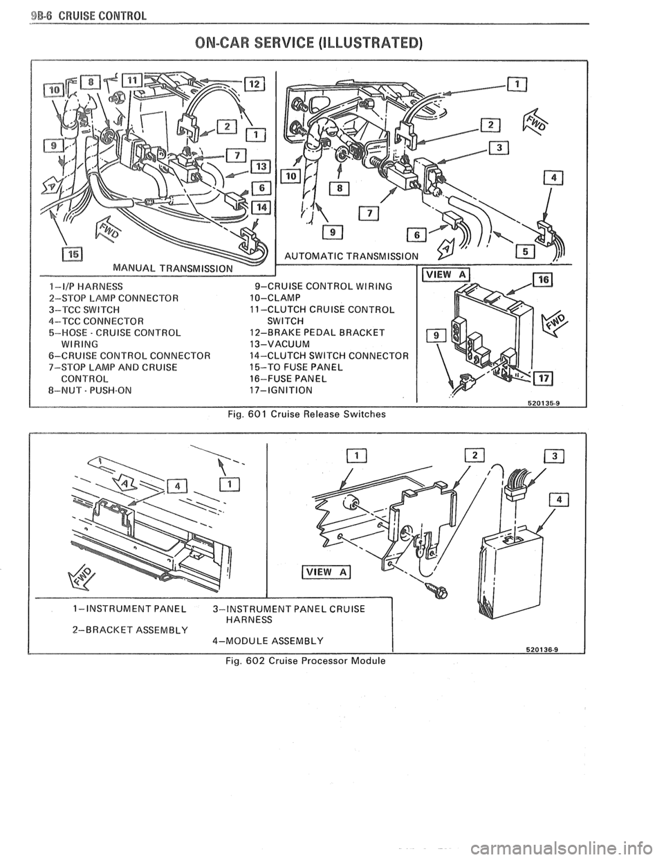
BB-8 CRUISE CONTROL
ON-CAR SERVICE (ILLUSTRAEED)
2-BRACKET ASSEMBLY 4-MODULE ASSEMBLY
Fig. 602 Cruise Processor Module
Page 1670 of 1825
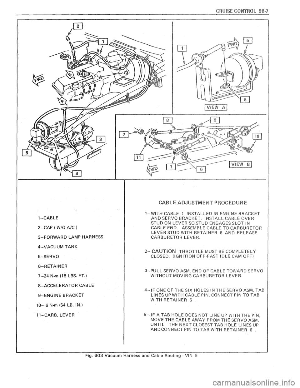
CRUISE CONTROL 9B-7
1 -CABLE
2-CAP
( W/O A/C )
3-FORWARD LAMP HARNESS
4-VACUUM TANK
5-SERVO 6-RETAINER
7-24
N.m (1 8 LBS. FT.)
8-ACCELERATOR CABLE
9-ENGINE BRACKET
10- 6 Nern (54 LB. IN.)
11-CARE. LEVER
CABLE ADJUSTMENT PROCEDURE
1-WITH CABLE 1 INSTALLED IN ENGINE BRACI
CABLE END. ASSEMBLE CABLE TO CARBIJRETOR LEVER STUB WITH RETAINER 6 AND RELEASE
CARBURETOR LEVER.
2- CAUT1BN THROTTLE MUST BE COMPLETELY
CLOSED. (IGNITION OFF-FAST IDLE CAM OFF)
3-PULL SERVO ASM. END OF CABLE TOWARD SERVO
WITHOUT MOVING CARBURETOR LEVER.
4-IF ONE OF THE
SIX HOLES IN THE SERVO ASM. TAB
LINES UP WlTH CABLE PIN, CONNECT PIN TO TAB
WlTH RETAINER 6 .
5-IF A TAB HOLE DOES NOT LINE UP WITH THE PIN,
MOVE THE CABLE AWAY FROM
THE SERVO ASM. UNTIL THE NEXT CLOSEST TAB HOLE LINES UP
ANBCONNECT PIN TO TAB WITH RETAINER 6 .
Fig. 603 Vacuum Harness and Cable Routing - VIN E