PONTIAC FIERO 1988 Service Repair Manual
Manufacturer: PONTIAC, Model Year: 1988, Model line: FIERO, Model: PONTIAC FIERO 1988Pages: 1825, PDF Size: 99.44 MB
Page 241 of 1825
3E-10 TIRES AND WHEELS
Clear Coat Damage on Unpainted Wheels
I.
Apply chemical stripper. Use small 1/4" detail
brush dipped in stripper to apply material around
perimeter and spoke-like areas.
2. Remove stripper following manufacturers
recommendations.
3. Sand wheel with 240 grit while rotating wheel on
a slow spinning brake lathe or by mounting on car
and spinning by hand. This will restore the
machined appearance and promote adhesion.
CAUTION: Do not use engine power to
rotate wheel while sanding to avoid
serious personal injury.
4. Continue with "Recoating Procedure."
Recoating Procedure
1. Clean surface of contaminants.
2. Soak wheel with Amchem #33 or equivalent
from
1 to 3 minutes, then rinse with water and
blow dry.
3. Soak wheel with Amchem
#I001 or equivalent
for
1 to 3 minutes, then rinse with water and blow
dry. 4.
Finish with Ditzler Delclear Acrylic Urethane
and Ditzler Ultra-Urethane Additive or
equivalent using three coats.
1st Coat
- Light mist coat, let flash
2nd Coat
- Light, let flash
3rd Coat
- Heavy double wet coat
CAUTION: To avoid serious personal
injury when applying any two part
component paint system, follow the
specific precautions provided by the
paint manufacturer. Failure to follow
these precautions may cause lung
irritation and allergic respiratory
reaction.
5. Let dry for 24 hours - (or flash for 30 minutes,
force dry at
140" for 30 minutes, and allow to cool
for 30 minutes before mounting.
WHEEL NUT TORQUE
F Carline - M 12X 1.5 .............. 1 10 N . m (80 Ibs. ft.)
Page 242 of 1825
PROPELLER SHAFT 4A-1
PROPELLER SHAFT
NOTICE: The propeller shaft to pinion flange or slip yoke fasteners are important attaching parts in that
they may affect the performance of vital components and systems, which may result in a major repair expense.
They must be replaced with one of the same part number or with an equivalent part, if replacement becomes
necessary. Do not use a replacement part of lesser quality or substitute design. Torque values must be used as
specified during reassembly to assure proper retention of these parts.
CONTENTS
GENERAL DESCRIPTION ........................ 4A-1
DIAGNOSIS ......................... ............ 4A-1
ON-VEHICLE SERVICE ........................... 4A-I
Propeller Shaft Run-Out
....................................... Measurement 4A- 1
Companion Flange Run-Out
Measurement
............................................. 4A-2
........... Universal Joint Angle Measurement 4A-3
............................ Propeller Shaft Balancing 4A-4
.............................................. Propeller Shaft 4A-8
Removal
.................... .. ............................. 4A-8
GENERAL DESCRIPTION
Figure 4A- I
.............................................. Installation 4A-8
UNIT REPAIR ............................................... 4A-9
Universal Joints
...................... ... ............ 4A-9
....................... Nylon Injected Ring Type 4A-9
..... ....................... Disassembly .... 4A-9
.......................................... Assembly 4A-9
......................... External Snap Ring Type 4A- l 1
............. .................... Disassembly .. 4A- 1 1
........................................... Assembly
4A- 1 1
.................... TORQUE SPECIFICATIONS 4A-12
.................................. SPECIAL TOOLS 4A-12
DIAGNOSIS
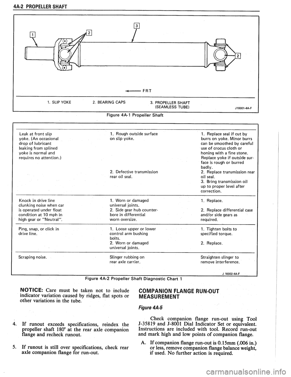
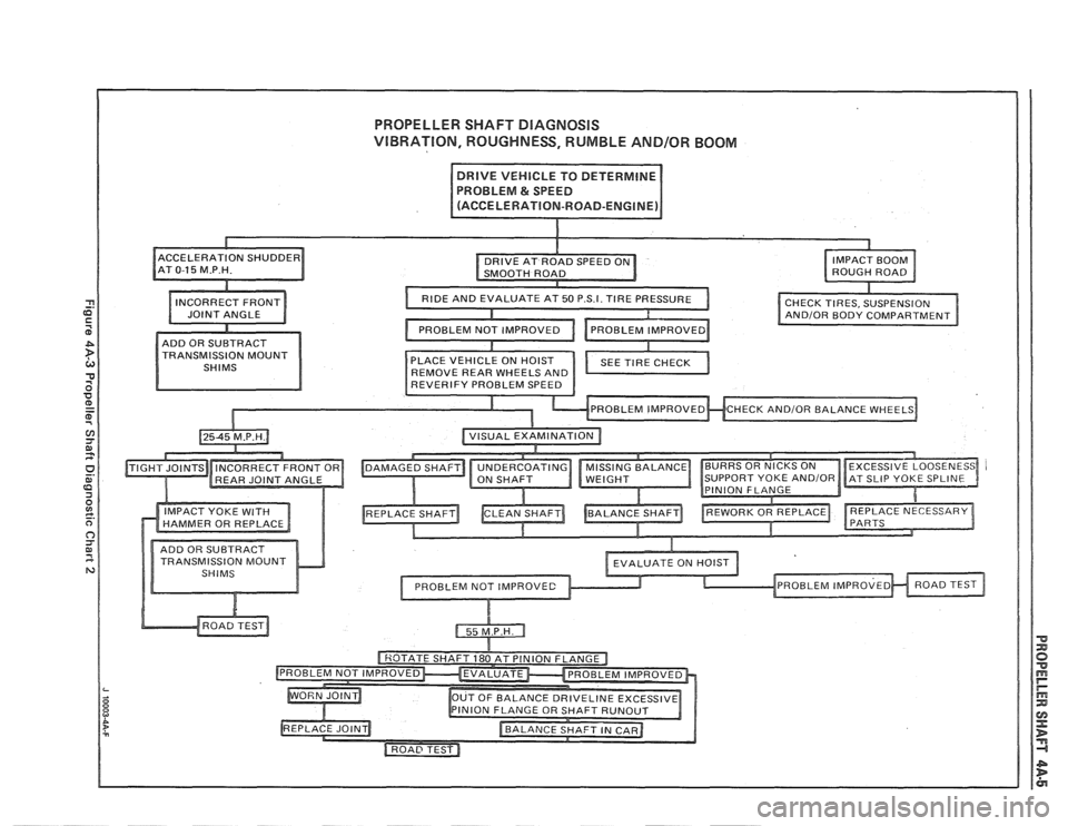
Figures 4A-2 and 4A-3
Obiectional vibration, roughness, rumble or
boom
can be caused by the input from a number of
shaft. use a One piece propeller systems. The following diagnostic charts provide a
systematic approach to finding the vehicle problem.
A universal joint and splined slip yoke are located at
the transmission end of the propeller shaft, where they are
held in alignment by a bushing in the transmission exten-
sion housing. The slip yoke permits fore and aft move-
ment of the propeller shaft, as the differential assembly
moves up and down. The spline is lubricated internally by
transmission fluid. A seal in the transmission extension
housing prevents fluid leakage and protects the slip yoke
from dust,
dirt, and other harmful material.
A second universal joint is used where the
propeller shaft connects to the rear axle pinion
companion flange.
The universal joints are lubricated for life and
cannot be lubricated while on the vehicle.
If it becomes
necessary to replace a universal joint, the entire
propeller shaft must be removed from the vehicle. Care
should be taken to avoid jamming, bending or
over-angulating of any parts of the assembly.
On vehicles with steel propeller shafts, production
universal joint bearing caps are retained by nylon injected
rings. Aluminum propeller shafts and all service replace-
ment universal joints use snap rings to retain the bearing
caps.
If a vehicle is to be undercoated, the propeller
shaft must be kept completely free of undercoating
material. Undercoating material or any other foreign
material will upset the propeller shaft balance and
produce serious vibration. To
determine whether the propeller shaft is
causing the problem, drive the vehicle through speed
range and note at which vehicle speed the problem is
most pronounced. Shift the transmission into a lower
gear range and drive the vehicle at the same speed as
when problem was most pronounced.
If the problem is still present at the same vehicle
speed, the propeller shaft may be at fault. Refer to the
propeller shaft diagnostic charts.
ON-VEHICLE SERVICE
PROPELLER SHAFT RUN-OUT MEASUREMENT
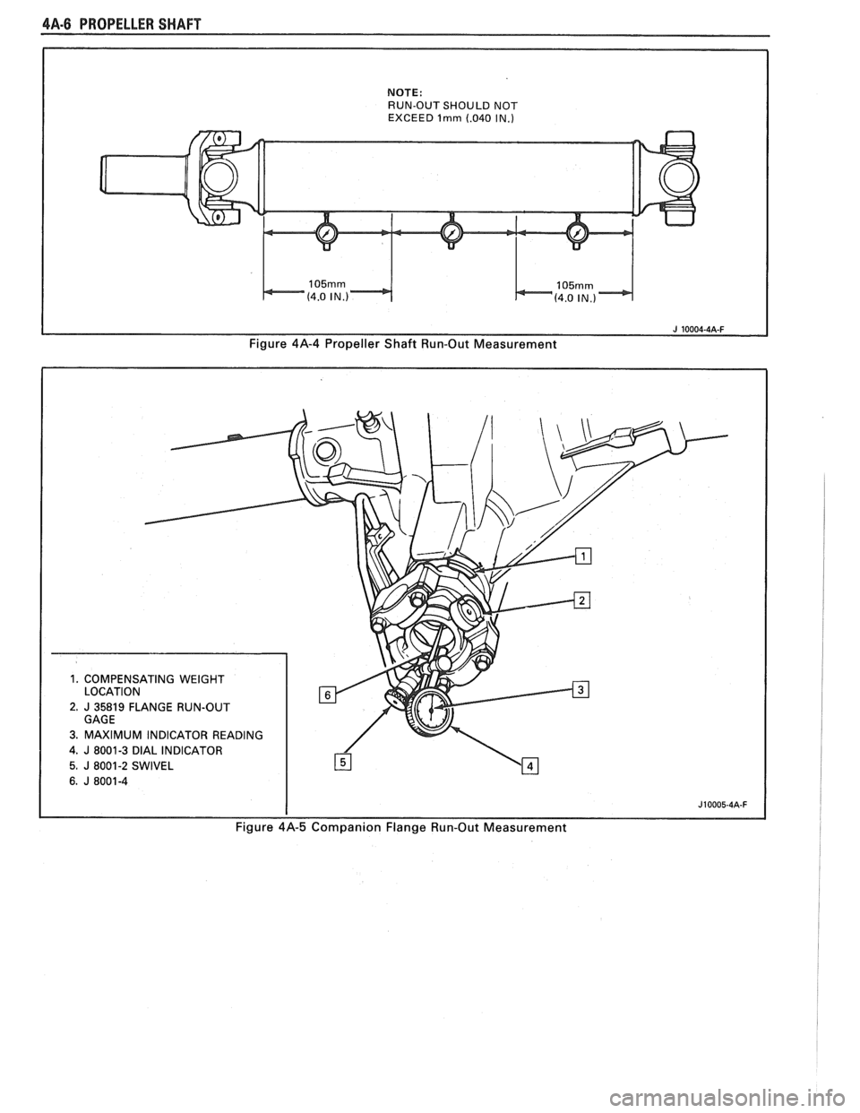
Figure 4A-4
If a noise or vibration is present at high speed it
might be caused by a bent shaft, or if a shaft has been
damaged through handling or a collision, it may be
checked for straightness as follows:
1. Raise vehicle on a twin post hoist so that the rear
is supported on the rear axle housing with wheels
free to rotate.
2. Mount
a dial indicator on a movable support that
is high enough to permit contact of the indicator
button with the propeller shaft or mount dial
indicator to a magnetic base and attach to a
suitable smooth place on the underbody of the
vehicle. Readings are to be taken at points
indicated, as shown.
3. With transmission in neutral, check for runout by
turning a rear wheel to rotate the propeller shaft.
Page 243 of 1825
4A-2 PROPELLER SHAFT
1. SLIP YOKE 2. BEARING CAPS 3. PROPELLER SHAFT
(SEAMLESS TUBE)
Figure 4A-1 Propeller Shaft
Leak
at front slip 1. Rough outside surface 1. Replace seal if cut by
yoke. (An occasional on
slip yoke. burrs on yoke.
Minor burrs
drop of lubricant can
be smoothed by careful
leaking from splined use
of crocus
cloth or
yoke
is normal and honing
with a fine stone.
requires no attention.) Replace
yoke if outside sur-
face is rough or burred
badly.
2. Defective transmission 2. Replace transmission rear
rear oil seal. oil seal.
3. Bring transmission oil
up to proper level after
correction.
Knock in drive line
1. Worn or damaged 1. Replace.
clunking noise when car universal
joints.
is operated under float 2. Side gear hub counter- 2. Replace differential case
condition at
10 mph in bore
in differential and/or side gears as
high gear or "Neutral". worn oversize. required.
Ping, snap, or click in
1. Loose upper or lower 1. Tighten bolts to
drive line. control arm bushing specified torque.
bolts.
2. Worn or damaged 2. Replace.
universal joints.
Scraping noise. Slinger
rubbing on
rear axle carrier. Straighten
slinger to
remove interference.
I
Figure 4A-2 Propeller Shaft Diagnostic Chart 1 I i
NOTICE: Care must be taken not to include COMPANION FLANGE RUN-OUT indicator variation caused by ridges, flat spots or MEASUREMENT other variations in the tube.
Figure 4.4-5
Check companion flange run-out using Tool
4. If runout exceeds specifications, reindex the 5-35819 and 5-8001 Dial Indicator Set or equivalent.
propeller shaft 180" at the rear axle companion Instructions are included with tool. Record run-out
flange and recheck runout. and mark high and low points of companion flange.
A. If companion flange run-out is
O.15mm (.006 in.)
5. If
runout is still over specifications, check rear
or less, remove companion flange balance weight,
axle companion flange for run-out.
if used. No further action is required.
Page 244 of 1825
PROPELLER SHAFT $A-3
B. If companion flange run-out is over 0.15mm (.006
in.) but less than 0.28mm (.011 in.) and balance
weight is at or near low point of companion flange
run-out, no further action is required.
If balance weight is not at or near low point of
companion flange run-out, remove weight.
6. If companion flange run-out is over 0.28mm (.011
in.), but no greater than 0.38mm (.015 in.) and
balance weight is at or near low point of
companion flange run-out, no further action is
required.
If balance weight is not at or near low point of
companion flange
runout, remove weight and
reindex companion flange until run-out is 0.25
mm
(.010 in.) or less.
If impossible to achieve
0.25mm (.010 in.) or less
run-out, install a new companion flange and
recheck for
0.25mm (.010 in.) or less run-out.
Service replacement companion flanges are not
equipped with balance weights and no weights
should be added.
UNIVERSAL JOINT ANGLE MEASUREMENT
When torque is transmitted through any ordinary
universal joint, the driven yoke fluctuates slightly in
speed. In other words, although the driving yoke
rotates at a constant speed, the driven yoke speeds up
and slows down twice per revolution. This flucutation
of the driven yoke is in direct proportion to the angle
through which the universal joint is operating; the
greater the angle, the greater the fluctuation.
Whenever two universal joints are used, this
fluctuation effect can be eliminated by staggering the
joints so that the two driving yokes are 90 degrees apart
provided the two joints are transmitting torque
through the same angle.
Therefore, when two universal joints are used, the
angles through which they operate must be very nearly the
same. This allows the alternate acceleration and decelera-
tion of one joint to be offset by the alternate acceleration
and deceleration of the second joint. When the two joints
do not run at approximately the same angle, operation is
rough and an objectionable vibration is produced.
The actual optimum angles desired must take into
consideration the effects of various passenger loadings
and rear axle windup during acceleration; therefore, it
is unlikely that the front and rear universal joint angles
will be found to be the same in actual practice.
In addition, universal joints are designed to
operate safely and efficiently within certain angles. If
the designed angle is exceeded, the joint may be broken
or otherwise damaged.
The front universal joint angle is actually the
angle between the engine-transmission centerline and
the propeller shaft centerline. This angle is determined
by the design of the frame assembly and may be altered
by adding or removing shims between the transmission
and the transmission mount.
Adding one shim at the transmission mount will
decrease the transmission universal joint angle by
1/2"
and increase differential universal joint angle by 1/4".
If one shim is removed the tranmission angle will
increase
1/2" and decrease differential angle I/@. The
production transmission mount bolt is an
M10-1.5 x 35
mm. When installing two or more shims, an
M10-1.5
x 50 mm bolt must be used.
All complaints of propeller shaft vibrations
should be accompanied by rear trim height
measurements at curb weight. An incorrect trim height
may cause some vibration. If vibration is severe
enough, removal or installation of spring shims may be
required. If any irregular roughness or vibration is
detectable in the drive line, the front and rear universal
joint angles should be checked. Should the vehicle
become involved in a severe rear end collision, or
should the rear axle carrier be replaced, the rear
universal joint angle should be checked and control
arms should be replaced if necessary.
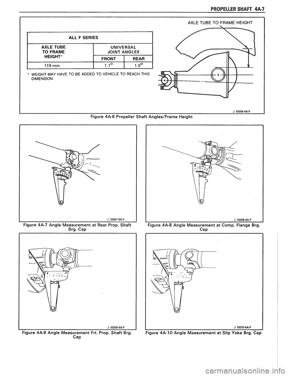
Figure 4A-6
This method can be used with the vehicle over a
pit or on a drive-on platform hoist, as long as the
vehicle is at curb weight with a full tank of gasoline.
Bounce vehicle up and down to assure curb height.
Before universal joint angles can be checked, the
measurements specified (the distance between the top
of the axle tube and the bottom of the frame) must be
met. To insure an accurate measurement, weight may
have to be added to the vehicle to reach these
specifications.
Readings should be taken at the following
locations in the following manner.
Angle Measurement at Rear Universal Joint
Figures 4A-7 and 4A-8
1. Place inclinometer J 23498-A on rear propeller
shaft bearing cap. Center bubble in sight glass and
record measurement. Bearing cap must be straight
up and down and free of dirt or other foreign mate-
rial to obtain an accurate measurement.
2. Rotate propeller shaft 90 degrees and place
inclinometer on the companion flange bearing
cap. Center bubble in sight glass and record
measurement.
3. Subtract smaller figure from larger figure to
obtain existing rear universal joint angle.
Angle Measurement at Front Universal Joint
Figures 4A.9 and 4A- 10
1. Place inclinometer on front propeller shaft
bearing cap. Center bubble in sight and record
measurement.
2. Rotate propeller shaft 90 degrees and place
inclinometer on the slip yoke bearing cap. Center
bubble on sight glass and record measurement.
3. Substract smaller figure from larger figure
lo
obtain existing front universal joint angle.
Page 245 of 1825
4A-4 PROPELLER SHAFT
PROPELLER SHAFT BALANCING
Hose Clamp Method
Figures 4A- 1 1 thru 4A-13
1. Place the vehicle on a twin post hoist so that the
rear of the vehicle is supported on the rear axle
housing and the rear wheels are free to rotate.
Remove both rear wheel assemblies and reinstall
wheel lug nuts with flat sides next to
drums/discs.
2. Mark and number propeller shaft at four (4)
points 90 degrees apart at rear of shaft just
forward of balance weight, as shown.
3. Install two (2) hose clamps on the rear of the
propeller shaft and slide them rearward until the
clamps stop at the nearest balance weight welded
to the tube. Align both clamps at any one of the
four marks made on shaft in Step 2 and tighten.
Be sure sufficient clearance is maintained so that
clamp heads do not contact floor pan of vehicle
when axle is in contact with rebound bumper in
frame. In order to gain sufficient clearance, it
may be necessary to position the clamps over the
balance weights.
4. Run the vehicle through the speed range to 80-90
MPH (130-145
Km/h) and note amount of
imbalance.
CAUTION: All persons should stay
clear of universal joint and balance
weight areas to avoid possible injury.
Do not run on hoist for extended
periods due to the danger of
overheating the transmission or
engine.
5. Loosen clamps and rotate clamp heads 90 degrees
to the next mark on a propeller shaft. Tighten
clamps and repeat Step 4.
6. Repeat Step 5 until car has been run with clamp
heads located at all four marks on shaft.
7. Position clamps at point of least imbalance.
Rotate the clamp heads away from each other 45
degrees (one on each side of the position), as
shown. Run the vehicle and note if imbalance has
improved.
In some cases it may be necessary to use one
clamp or possibly three clamps in order to obtain
a good balance. Replace shaft if three hose clamps
do not improve the imbalance.
8. Continue to rotate the clamps apart in smaller
angular increments until the imbalance is at its
minimum.
9. Reinstall wheel assemblies and road test the
vehicle for final check of balance. A minimal
vibration felt in the vehicle on the hoist may not
show up during a road test.
Strobe Light Method
Figures 461- 1 1, $A- 14, and 4A- 15
If a wheel balancer of the strobe light type is
available, the use of such a unit will facilitate the
balancing of the propeller shaft. The balance pick-up
unit should be placed directly under the nose of the
rear axle carrier and as far forward as possible. 1.
Place
the vehicle on a twin post hoist so the rear of
the vehicle is supported on the rear axle housing and
the rear wheels are free to rotate. Lower rear hoist
and allow axle to rest on jackstands. The groove in
the rear hoist fixture could clamp the axle and de-
stroy the sensitivity of the operation. Remove both
rear wheel assemblies and reinstall wheel lug nuts
with flat sides next to the
drums/rotors.
2.
Mark and number drive shaft at 4 points 90
degrees apart at rear of shaft just forward of
balance weights, as shown.
3. Place the strobe light wheel balancer pick-up
under the nose of the carrier.
4. Run vehicle in gear at the speed where the
distrubance is at its peak, allow the driveline to
stabilize by holding at a constant speed. Point
strobe light up at the spinning propeller shaft and
note position of one of the reference numbers.
Shut off engine and position the propeller shaft so
the reference numbers will be in the same position
as was noted while the shaft was rotating.
When strobe light flashed, the heaviest point of
the shaft was at the bottom (6 o'clock). To
balance the propeller shaft, it would be necessary
to apply the balancing weights (hose clamps) 180
degrees away from the heaviest point or at the top
of the propeller shaft (12 o'clock).
5. Install two screw-type hose clamps on the
propeller shaft as close to the rear as possible.
Position both clamp heads 180 degrees from the
heaviest point of drive shaft as indicated by strobe
light. Tighten clamps.
NOTICE: Be sure sufficient clearance is
maintained so clamp heads do not contact floor
pan of vehicle when axle is in contact with rebound
bumper on frame. In order to gain. sufficient
clearance, it may be necessary to position the
clamps over the balance weights.
6. Run vehicle through the speed range 80-90
M.P.
H. (130-145 Km/h). If disturbance is gone,
nothing further need be done on the hoist. If the
disturbance is not gone and the strobe light shows
the clamp heads at the bottom (6 o'clock) of the
shaft, go to Step
7. If the strobe light shows the
two clamp heads at the top of the shaft, add one
more hose clamp and recheck. If the strobe light
shows the three clamp heads at the top of the
shaft, remove the propeller shaft and
reindex it
180 degrees on the rear axle pinion companion
flange. Recheck with no clamps. Repeat balance
starting with Step 5. If the shaft still needs more
than three hose clamps at the same clock position,
replace it. If the clamps are also 180 degrees from
their original position after the propeller shaft
was reindexed 180 degrees, the rear axle pinion
companion flange is out of balance and must be
replaced. DO NOT use more than three hose
clamps to balance the shaft. If the strobe light
shows the hose clamps at the bottom of the shaft,
but the disturbance still exists, go to Step
7.
Page 246 of 1825
PROPELLER SHAFT DlAGNOSlS
VIBRATION, ROUGHNESS, RUMBLE AND/OR BOOM
IMPACT YOKE WITH
TRANSMISSION MOUNT
Page 247 of 1825
4A-6 PROPELLER SHAFT
NOTE: RUN-OUT SHOULD NOT EXCEED lrnrn (.040 IN.)
Figure 4A-4 Propeller Shaft Run-Out Measurement
Page 248 of 1825
PROPELLER SHAFT 4A-7
* WEIGHT MAY HAVE TO BE ADDED TO VEHICLE TO REACH THIS DIMENSION.
Figure 4A-6 Propeller Shaft Angles/Frame Height
Figure 4A-7 Angle Measurement at Rear Prop. Shaft
Brg. Cap
Figure
414-9 Angle Measurement Frt. Prop. Shaft Brg.
Cap
Figure 4A-8 Angle Measurement at Comp. Flange Brg.
Cap
Figure 4A-10 Angle Measurement at Slip Yoke Brg. Cap
Page 249 of 1825
4A-8 PROPELLER SHAFT
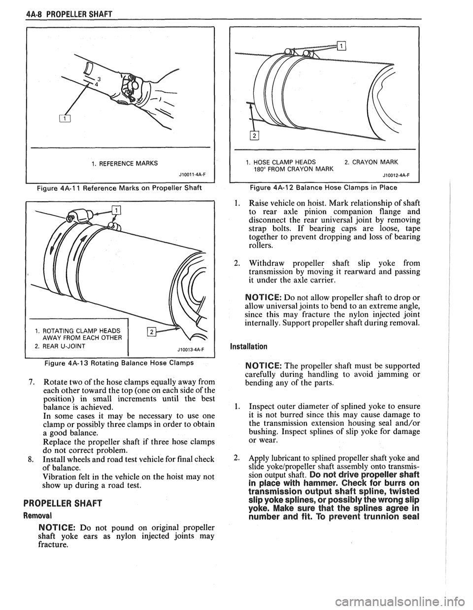
1. REFERENCE MARKS
J10011-4A-F
Figure 4A-1 1 Reference Marks on Propeller Shaft
1 2. REAR U-JOINT
1. HOSE CLAMP HEADS 2. CRAYON MARK 180" FROM CRAYON MARK
Figure 4A-12 Balance Hose Clamps in Place
1. Raise vehicle on hoist. Mark relationship of shaft
to rear axle pinion companion flange and
disconnect the rear universal joint by removing
strap bolts. If bearing caps are loose, tape
together to prevent dropping and loss of bearing
rollers.
2. Withdraw propeller shaft slip yoke from
transmission by moving it rearward and passing
it under the axle carrier.
NOTICE: Do not allow propeller shaft to drop or
allow universal joints to bend to an extreme angle,
since this may fracture the nylon injected joint
internally. Support propeller shaft during removal.
Installation
Figure 4A-13 Rotating Balance Hose Clamps
7. Rotate two of the hose clamps equally away from
each other toward the top (one on each side of the
position) in small increments until the best
balance is achieved.
In some cases it may be necessary to use one
clamp or possibly three clamps in order to obtain
a good balance.
Replace the propeller shaft if three hose clamps
do not correct problem.
8. Install wheels and road test vehicle for final check
of balance.
Vibration felt in the vehicle on the hoist may not
show up during a road test.
PROPELLER SHAFT
Removal NOTICE:
The
propeller shaft must be supported
carefully during handling to avoid jamming or
bending any of the parts.
1. Inspect outer diameter of splined yoke to ensure
it is not burred since this may cause damage to
the transmission extension housing seal and/or
bushing. Inspect splines of slip yoke for damage
or wear.
Apply lubricant to splined propeller shaft yoke and
slide yokelpropeller shaft assembly onto transmis-
sion output shaft.
Do not drive propeller shaft
in place with hammer.
Check for burrs on
transmission output shaft spline, twisted slip yoke splines, or possibly the wrong slip
yoke. Make sure that the splines agree in
number and fit. To prevent trunnion seal
NOTICE: Do not pound on original propeller
shaft yoke ears as nylon injected joints may
fracture.
Page 250 of 1825
PROPELLER SHAFT 4A-9
damage, do not place any tool betvveen pro-
peller shaft yoke and the universal joint
spider.
When making the rear propeller shaft connection,
be sure to align marks made on the pinion flange and
propeller shaft prior to removal.
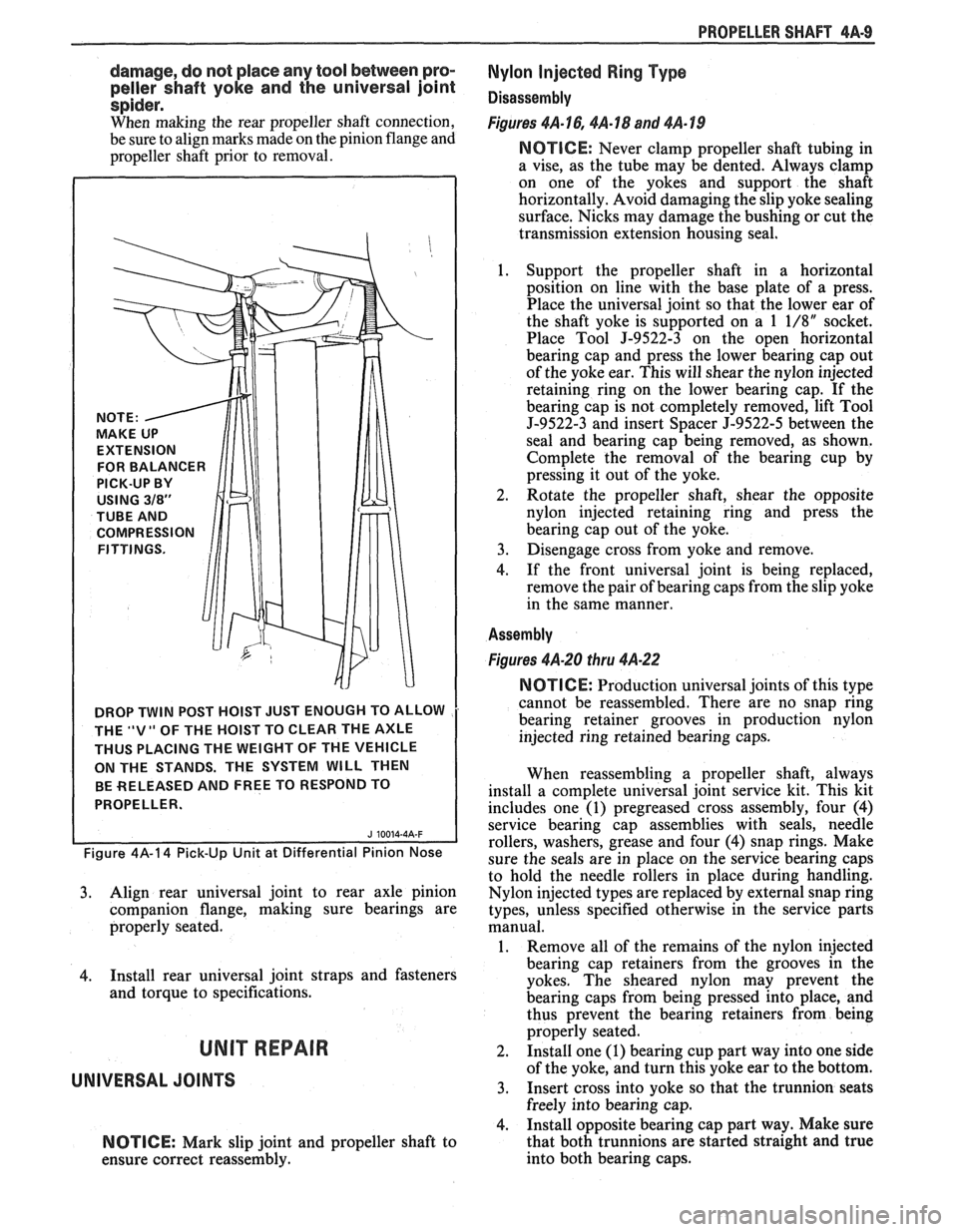
DROP TWIN POST HOIST JUST ENOUGH TO ALLOW
THE
"V" OF THE HOIST TO CLEAR THE AXLE
THUS PLACING THE WEIGHT OF THE VEHICLE
ON THE STANDS. THE SYSTEM
WILL THEN
BE RELEASED AND FREE TO RESPOND TO
PROPELLER.
Figure 4A-14 Pick-Up Unit at Differential Pinion Nose
3. Align rear universal joint to rear axle pinion
companion flange, making sure bearings are
properly seated.
4. Install rear universal joint straps and fasteners
and torque to specifications.
UNIT REPAIR
UNIVERSAL JOINTS
NOTICE: Mark slip joint and propeller shaft to
ensure correct reassembly.
Nylon Injected Ring Type
Disassembly
Figures 4A-16,4A-18 and 4A-19
NOTICE: Never clamp propeller shaft tubing in
a vise, as the tube may be dented. Always clamp
on one of the yokes and support the shaft
horizontally. Avoid damaging the slip yoke sealing
surface. Nicks may damage the bushing or cut the
transmission extension housing seal.
1. Support the propeller shaft in a horizontal
position on line with the base plate of a press.
Place the universal joint so that the lower ear of
the shaft yoke is supported on a
1 1/8" socket.
Place Tool
J-9522-3 on the open horizontal
bearing cap and press the lower bearing cap out
of the yoke ear. This will shear the nylon injected
retaining ring on the lower bearing cap. If the
bearing cap is not completely removed, lift Tool
5-9522-3 and insert Spacer J-9522-5 between the
seal and bearing cap being removed, as shown.
Complete the removal of the bearing cup by
pressing it out of the yoke.
2. Rotate
the propeller shaft, shear the opposite
nylon injected retaining ring and press the
bearing cap out of the yoke.
3. Disengage cross from yoke and remove.
4. If the front universal joint is being replaced,
remove the pair of bearing caps from the slip yoke
in the same manner.
Assembly
Figures 4A-20 thru 4A-22
NOTICE: Production universal joints of this type
cannot be reassembled. There are no snap ring
bearing retainer grooves in production nylon
injected ring retained bearing caps.
When reassembling a propeller shaft, always
install a complete universal joint service kit. This kit
includes one
(1) pregreased cross assembly, four (4)
service bearing cap assemblies with seals, needle
rollers, washers, grease and four
(4) snap rings. Make
sure the seals are in place on the service bearing caps
to hold the needle rollers in place during handling.
Nylon injected types are replaced by external snap ring
types, unless specified otherwise in the service parts
manual.
1. Remove all of the remains of the nylon injected
bearing cap retainers from the grooves in the
yokes. The sheared nylon may prevent the
bearing caps from being pressed into place, and
thus prevent the bearing retainers from being
properly seated.
2. Install one (1) bearing cup part way into one side
of the yoke, and turn this yoke ear to the bottom.
3. Insert cross into yoke so that the trunnion seats
freely into bearing cap.
4. Install opposite bearing cap part way. Make sure
that both trunnions are started straight and true
into both bearing caps.