PONTIAC FIERO 1988 Service Repair Manual
Manufacturer: PONTIAC, Model Year: 1988, Model line: FIERO, Model: PONTIAC FIERO 1988Pages: 1825, PDF Size: 99.44 MB
Page 271 of 1825
484-18 REAR AXLE
4. With transmission in park and both wheels and
tires clear of ground, (wheels will r~tate in opp-
osite directions), measure torque required to
rotateaxle shafts with a torque
wrenchattached
to J 2619-1. If the torque reading is less than
48 N.m (35 1b.ft.) the unit should be disassembled
and repaired as required.
5. Reinstall wheel and tire assembly.
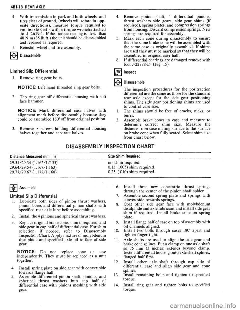
Disassemble
Limited Slip Differential.
1. Remove ring gear bolts.
NOTICE: Left hand threaded ring gear bolts.
2. Tap
ring gear off differential housing with soft
face hammer.
NOTICE: Mark differential case halves with
alignment mark before disassembly because they
could be assembled
180" off from original position.
3. Remove 8 screws holding differential housing
halves together and separate halves. 4.
Remove pinion shaft, 4 differential pinions,
thrust washers side gears, side gear shims
(if
required), spring plates, and compression springs
from housing. Discard compression springs. New
springs are required for assembly.
5. Mark each cone during disassembly to ensure
that the same brake cone will be assembled with
the same case as originally assembled. If shims
are used they must be marked so that they will be
assembled in original case half.
6. If differential bearings are damaged remove with
tool J-22888-D. (Fig. 15).
Inspect
Disassemble
The inspection procedures for the positraction
differential are the same as those for the standard
rear axle except for the side gear positioning
shims. The side gear positioning shims are used
to control case size.
1. The shims should be free of cracks, nicks, or
burrs.
2. Assemble brake cones in case and measure to
determine correct shim size. Measure the
distance from case mating surface to flat surface
on brake cone when fully seated. Select shim size
from chart below.
DISASSEMBLY INSPECTION CHART
Distance Measured mm (ins) Size
Shim Required
29.51/29.34 (1.162/1/155) no shim required.
29.64/29.54 (1.167/1.163) 0.13 (.005) shim required.
29.77D9.67 (1.172/1.168) 0.25 (.010) shim required.
Assemble
Limited Slip Differential
1.
Lubricate both sides of pinion thrust washers,
pinion bores and differential pinion shafts with
specified rear axle lube before assembling.
2. Install the 4 pinions and spherical thrust washers.
3. Replace original brake cone, shim if required, and
side gear in cap half of differential case. For shim
selection, if needed, refer to Disassembly
Inspection Chart. Apply mixture of molybdenum
disulphide and specified axle oil to face of side
gear.
NOTICE: Do not 1.eplace cone or case
independently. They must be replaced as a unit
together.
4. Install spring
plate on side gear with convex side
towards flange half.
5. Assemble differential pinion shaft, pinions, and
spherical thrust washers into cap half of
differential case with pinions meshing with side
gear. 6.
Install three new concentric thrust springs
through the center of the pinion shaft spider.
7. Assemble second spring plate and springs with
cgnvex side towards springs.
8. Coat other side gear face with molybdenum
disulphide and axle lubricant and install side gear
shim if required. Install brake cone on spring
plate.
9. Install
flange half of case on top of assembly with
oil channels aligned.
10. Install
two bolts through cases
180" apart and
tighten finger tight.
11. Axle shafts are used to align the side gear and
brake cone splines. Put a clamp on one axle shaft
so 75 mm (3 inches) extends beyond clamp.
Install differential housing onto axle shaft splines,
flanged half first.
12. Install other axle shaft through cap side of
differential case and align side gear and cone
splines.
13. Install remaining
bolts and tighten to specified
torque.
14. Install
ring gear and tighten bolts to specified
torque.
Page 272 of 1825
REAR AXLE 481-19
15. Press differential bearings on with tool J-21784 gear
and cone splines will occur, preventing
(Fig. 16). assembly
of remaining axle shaft. If this occurred,
16. Install assembled case into carrier following the repeat
assembly steps
11 and 12.
same procedures as developed for standard
differential.
Important
17. Installation of axle bearings and axles is the same
as standard axles. CAUTION: Do not run engine with
transmission engaged and only one
rn Important rear
wheel of vehicle elevated if rear
axle is equipped with limited slip
NOTICE:
After installing the limited slip differential. The other rear wheel will
differential in the carrier housing, be sure that both drive if in contact with the ground.
axle shafts are assembled before rotating either This action can result in damage to
axle shafts. If rotation of either axle shaft occurs the equipment or injury to the
before other is in position, misalignment of the side operator.
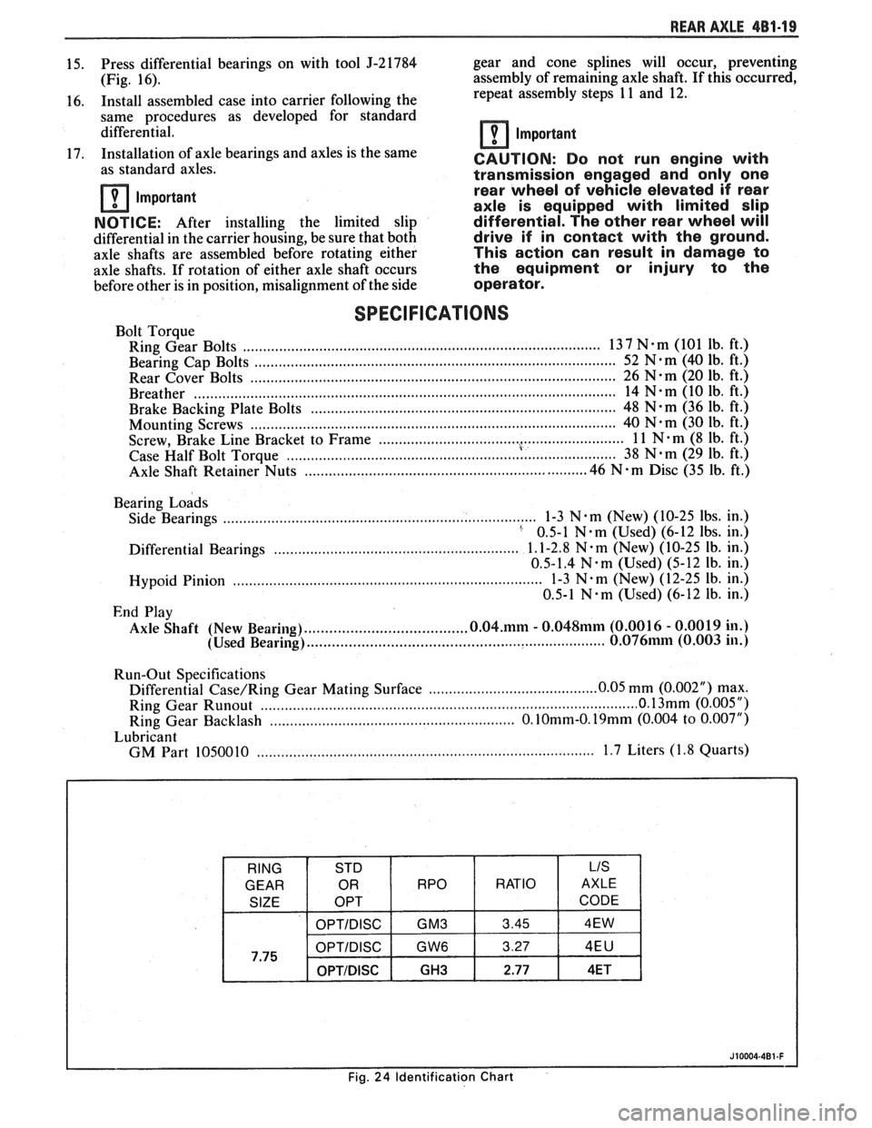
SPECIFICATIONS
Bolt Torque
Ring Gear Bolts
................................................................................... 13 7 N-m (101 lb. ft.)
......................................................................................... Bearing Cap Bolts 52 N-m (40
lb. ft.)
Rear Cover Bolts
........................ .. ............................................................. 26 N-m (20 lb. ft.)
........................................................................................................ Breather 14 N-m (10 Ib. ft.)
Brake Backing Plate Bolts
........................................................................... 48 N-m (36 lb. ft.)
Mounting Screws
...................... .. ............................................................... 40 N-m (30 lb. ft.)
............................................................. . Screw, Brake Line Bracket to Frame 1 1 N m (8 lb. ft.)
.......................................................... ....................... Case Half Bolt Torque 38 N.m (29 lb.
ft.)
.......................... Axle Shaft Retainer Nuts .................................... .... 46 N . m Disc (35 lb. ft.)
Bearing
Loads
Side Bearings .............................................................................. 1-3 N em (New) (10-25 lbs. in.) ' 0.5-1 N-m (Used) (6-12 lbs. in.)
............................................................. Differential Bearings 1.1-2.8 N. m (~ew) (10-25 lb.
in.)
0.5-1.4
N.m (Used) (5-12 lb. in.)
............................................................................. Hypoid Pinion 1-3 N.m (New)
(12-25 lb. in.)
0.5-1
N.m (Used) (6-12 lb. in.)
End Play
....................................... Axle Shaft (New Bearing) 0.04.mm - 0.048mm (0.001 6 - 0.0019 in.)
........................................................................ (Used Bearing) 0.076mm (0.003 in.)
Run-Out Specifications
.......................................... Differential Case/Ring Gear Mating Surface 0.05
mm (0.002") max. ................................................... ........................... Ring Gear Runout ............. 0 1 (0.005 ")
Ring Gear Backlash .......................................................... O.10mm-O.19mm (0.004 to 0.007")
Lubricant
....................... ................................................... GM Part 1050010 .. 1.7 Liters (1.8 Quarts)
Page 273 of 1825
4B1-20 REAR AXLE
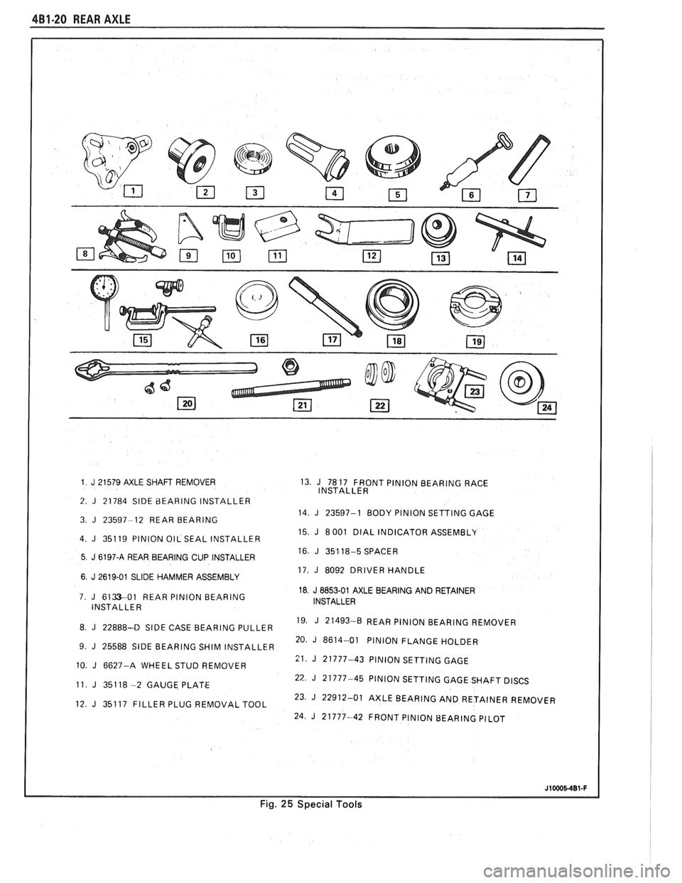
1 J 21 579 AXLE SHAFT REMOVER 13. J 78 17 FRONT PINION BEARING RACE
INSTALLER
2.
J 21784 SlDE 8EARlNG INSTALLER 14. J 23597-1 BODY PlNlON SETTING GAGE
3. J 23597-12 REAR BEARING
15. J 8 001 DIAL INDICATOR ASSEMBLY
4. J 35119 PlNlON OIL SEAL INSTALLER
16.
J 351 18-5 SPACER 5 J 6197-A REAR BEARING CUP INSTALLER
17. J 8092 DRIVER HANDLE
6 J 2619-01 SLIDE HAMMER ASSEMBLY
18
J 8853-01 AXLE BEARING AND RETAINER
7. J 6133-01 REAR PlNlON BEARING
INSTALLER INSTALLER
19. J 21493-0 REAR
PlNlON BEARING REMOVER
8. J 22888-43 SIDE CASE BEARING PULLER
20.
J 8614-01 PlNlON FLANGE HOLDER
9. J 25588 SlDE BEARING SHIM INSTALLER
11. J 21777-43 PlNlON SETTING GAGE 10. J 6627-A WHEEL STUD REMOVER
22
J 21777-45 PlNlON SETTING GAGE SHAFT DISCS
11 J 351 18 -2 GAUGE PLATE
23.
J 22912-01 AXLE BEARING AND RETAINER REMOVER
12. J 35117 FILLER PLUG REMOVAL TOOL
24.
J 21777-42 FRONT PlNlON BEARING PILOT
J10005-401-F
Fig. 25 Special Tools
Page 274 of 1825
REAR AXLE 4B-1
SECTION 4B
REAR AXLE
NOTICE: All rear axle attaching fasteners are an necessary.
Do not use a replacement part of lesser
important part in that they could affect the quality
or substitute design. Torque values must
performance of vital parts and systems, and/or be
used as specified during reassembly to assure
could result in major repair expense. They must proper retention
of all parts. (There is to be no
be replaced with one of the same part number or welding
as it may result in extensive damage and
with an equivalent part if replacement becomes weakening
of the metal.)
CONTENTS
General Description .................................. 4B-1
Standard Rear Axle ................... .. ............ 4B- 1
Diagnosis and Testing ............................... 4B-1
Axle Noises ......................... .. ................ 4B-3
Gear Noise ...................... .. .................. 4B-3
Bearing Noise ........................................ 4B-3
Rear Wheel Bearing Noise ....................... 4B-3
Knock at Low Speeds ............................. 4B-3
Backlash Clunk ...................................... 4B-3
Rear Axle Standard and Limited Slip .......... 4B-3
Pre-Repair Investigation and Trouble
Diagnosis
................................................. 4B-4
Gear Tooth Nomenclature ....................... 4B-4
Tooth Contact Pattern Test ..................... 4B-4
Effects of Increasing Load on
Teeth Contact Pattern
.......................... 4B-4
Adjustments Affecting Tooth
Contact
.................................................. 4B-6
Effects of Pinion Position on Tooth
Pattern
................... ... .................... 4B-6
General information ....................... .. ..... 4B-8
Limited-Slip Rear Axle ............................... 4B-8
On-Vehicle Service ............................. .. ....... 4B-8
Carrier Cover and Gasket .......................... 4B-8
............................................. Axle Shaft 4B-8
Oil Seal and/or Bearing (With
Axle Shaft Removed)
............................. 4B-9
........................................ Pinion Oil Seal 4B-9
........................................... Pinion Flange 4B- 10
..................................... Rear Wheel Bolt 4B- 1 1
.................................................... Unit Repair 4B-1 1
..................................... Rear Axle Assembly 4B- 1 1
Disassembly of Rear Axle
............................................... Assembly 4B- 1 1
.. ..................................... Case Assembly ... 4B- 12
Drive Pinion, Bearing and Races ............. 4B- 12
............................... Bearing Replacement 4B- 12
...................... Setting Drive Pinion Depth 4B- 13
........................................ Rear Axle Case 4B- 14
Side Bearing Preload Adjustment ............ 4B- 15
.................................................. Drive Pinion 4B- 16
Rear Axle Backlash Adjustment .............. 4B- 17
........... Limited Slip Rear Axle (Cone Type) 4B-17
...................................... Auburn Cone Type 4B- 18
.............................................. Specifications 4B- 19
.............................................. Special Tools 4B-20
GENERAL DESCRIPTION
STANDARD REAR AXLE Operation
The rear axle assembly is of the semi-floating type
in which the car weight is carried on the axle housing.
The rear axle assembly is designed for use with an open
drive line and coil springs. The rear axle has a
hypoid
type ring gear and pinion with the centerline of the
pinion gear below the centerline of the ring gear.
All parts necessary to transmit power from the
propeller shaft to the rear wheels are enclosed in a When
the vehicle turns a corner, the outer rear
wheel must turn faster than the inner wheel. The inner
wheel, turning slower than the outer wheel, slows its
differential side gear (as the axle shaft is splined to the
side gear) and the differential pinion gears will roll
around the slowed differential side gear, driving the
other differential side gear and wheel faster.
DIAGNOSIS AND "TESTING
salisbury type axle housing (a carrier casting with tubes Many
noises reported as coming from the rear
pressed and welded into the carrier to form a complete axle assembly actually
originate from other sources
carrier and tube assembly). A removable steel cover such as
tires, road surfaces, wheel bearings, engine,
bolted to the rear of the carrier permits service of the transmission,
muffler or body drumming. A thorough
rear axle without removing the entire assembly from and
careful check should be made to determine the
the car. source
of the noise before disassembling the rear axle.
Page 275 of 1825
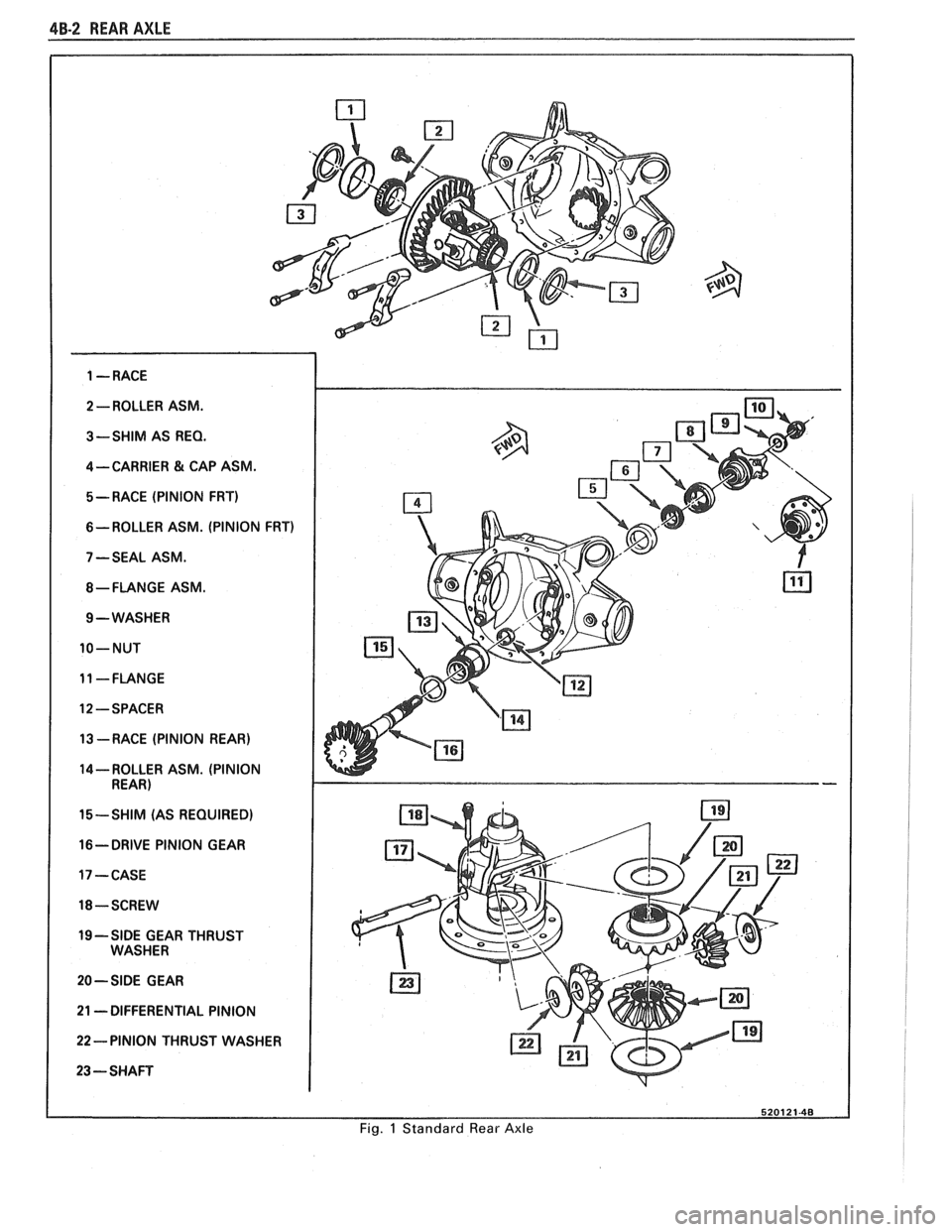
48-2 REAR AXLE
2 -ROLLER ASM.
3-SHIM AS
REQ.
4-CARRIER & CAP ASM.
5- RACE (PINION FRT)
6-ROLLER ASM. (PINION FRT)
7 -SEAL ASM.
$-FLANGE ASM.
9 -WASHER
10-NUT
11 -FLANGE
12 -SPACER
13 --RACE (PINION REAR)
14- ROLLER ASM. (PINION
REAR)
15-SHIM (AS REQUIRED)
16- DRIVE PINION GEAR
17 -CASE
18-SCREW
19 -SIDE GEAR THRUST
WASHER
20-SIDE GEAR
21
-DIFFERENTIAL PINION
22- PINION THRUST WASHER
23 ---SHAFT
520121-48
Fig. 1 Standard Rear Axle
Page 276 of 1825
REAR AXLE 4B-3
Noise which originates in other places cannot be
corrected by adjustment or replacement of parts in the
differential. It should also be remembered that rear
axle gears, like any other mechanical device, are not
absolutely quiet and should be accepted as being
commercially quiet unless some abnormal noise is
present.
To make a systematic check for axle noise under
standard conditions, observe the following:
1. Select a level smooth asphalt road to reduce tire
noise and body drumming.
2. Check rear axle lubricant to assure correct level,
then drive car far enough to thoroughly warm up
rear axle lubricant.
3. Note speed and RPM at which noise occurs. Then
stop car and with automatic transmission in neutral,
run engine slowly up and down through engine speeds, corresponding to car speed at which noise
was most pronounced, to determine if it is caused by
exhaust, muffler roar or other engine conditions.
4. Tire noise changes with different road surfaces,
but rear axle noise does not. Temporarily
inflating all tires to approximately 50 pounds
pressure for
test purposes only will materially
alter noise caused by tires, but will not affect noise
caused by rear axle. Rear axle noise usually stops
when coasting at speeds under 30 miles per hour;
however, tire noise continues, but with lower
tone, as car speed is reduced. Rear axle noise
usually changes when comparing acceleration
and coast, but tire noise remains about the same.
Distinguish between tire noise and rear axle noise
by noting if noise varies with various speeds or
sudden acceleration and deceleration; exhaust
and axle noise show variations under these
conditions while tire noise remains constant and
is more pronounced at speeds of 20 to 30 miles
per hour. Further check for tire noise by driving
car over smooth pavements or dirt roads (not
gravel) with tires at normal pressure. If noise is
caused by tires, it will noticeably change or
disappear and reappear with changes in road
surface.
5. Loose or rough front wheel bearings will cause
noise which may be confused with rear axle
noises; however, front wheel bearing noise does
not change when comparing drive and coast.
Light application of brakes while holding car
speed steady will often cause wheel bearing noise
to diminish, as this takes some weight off the
bearing. Front wheel bearings may be easily
checked for noise by jacking up the wheels and
spinning them, also by shaking wheels to
determine if bearings are loose.
6. Rear suspension rubber bushings and spring
insulators dampen out rear axle noise when
correctly installed. Check to see that no metallic
contact exists between the spring and spring
opening in frame or between upper and lower
control arm bushings and frame or axle housing
brackets.
Metal-to-metal contact at those points
may result in telegraphing road noise and normal axle
noise which would not be objectionable if
dampened by bushings.
AXLE NOISES
Gear Noise
After the noise has been determined as being in
the
axle by following the above appraisal procedure,
the type of axle noise should be determined to aid in
maki~~g repairs if necessary.
Gear noise (whine) is audible from 20 to
55 mph
under four driving conditions:
1. Drive - Acceleration or heavy pull.
2. Road Load - Car driving load or constant speed.
3. Float
- Using
enough throttle to keep the car from
driving the engine
- car slows down gradually but
engine still pulls slightly.
4. Coast
- Throttle closed and car in gear. Gear
noise most frequently has periods where noise is
more prominent, usually 30 to 40 mph and 50 to
55 mph.
Bearing Noise
Bad bearings generally produce more of a rough
growl or grating sound, rather than the whine typical
of gear noise. Bearing noise frequently "wow-wows" at
bearing rpm, indicating a defective pinion or rear axle
case side bearing. This noise could easily be confused
with rear wheel bearing noise. Inspect and replace as
required.
Rear Wheel Bearing Noise
A rough rear wheel bearing produces a noise
which continues with car coasting at low speed and
transmission in neutral. Noise may diminish some by
gentle braking. With rear wheels jacked up, spin rear
wheels by hand while listening at hubs for evidence of
rough (noisy) wheel bearing.
I(noclc At Low Speeds
Low speed knock can be caused by worn
universal joints or a side gear hub counterbore in a case
that has worn oversize. Inspect and replace universal
joint or case and side gear as required.
Baclclash Clunk
Excessive clunk with acceleration and
deceleration is caused by worn differential pinion shaft,
excessive clearance between axle shaft and side gear
splines, excessive clearance between side gear hub and
counterbore in case worn pinion and side gear teeth,
worn thrust washers and excessive drive pinion and
rear gear backlash. Remove worn parts and replace as
required, selecting close fitting parts when possible.
Adjust pinion and ring gear backlash.
REAR AXLE STANDARD AND LIMITED-SLIP
1. Noise is the same in "Drive" or "Coast".
a. Road noise.
b. Tire noise.
c. Front wheel bearing noise.
Page 277 of 1825
4B-4 REAR AXLE
d. Incorrect driveline angle.
Noise changes on a different type of road.
a. Road noise.
b. Tire noise.
Noise tone lowers as car speed is lowered.
a. Tire noise.
Similar noise is produced with car standing and
driving.
a. Engine noise.
b. Transmission noise.
Vibration. a. Rough rear wheel bearing.
b. Unbalanced
or damaged propeller shaft.
c. Tire unbalance.
d. Worn
universal joint in propeller shaft.
e. Incorrect driveline angle.
f. Mis-indexed propeller shaft at pinion
flange.
g. Pinion
flange
runout too great.
A knock or click approximately every two
revolutions of the rear wheel.
a. A rear wheel bearing.
Noise most pronounced on turns.
a. Rear
axle side gear and pinion noise.
A continuous low pitch whirring or scraping
noise starting at relatively low speed.
a. Pinion bearing noise.
Drive noise, coast noise or float noise.
a. Ring and
pinion gear noise.
Clunk on acceleration or deceleration.
a. Worn rear
axle pinion shaft in case or side
gear hub counterbore in case worn oversize.
b. Insufficient
lubrication on propeller shaft
slip yoke.
c. Worn U-joints on
propeller shaft. Front or
rear.
Groan in "Forward" or "Reverse".
a. Wrong
or contaminated lube in rear axle.
b. Worn bushings.
Chatter on turns.
a. Wrong
or contaminated lube in rear axle.
b. Clutch
cone worn and/or
spring(s) worn.
Clunk or knock on rough road operation.
a. Excessive end play of axle shafts to
differential cross shaft.
b. Worn bushings.
PRE-REPAIR INVESTIGATION AND TROUBLE
DIAGNOSIS
A careful1 diagnosis of the rear axle prior to
disassembly will often reveal valuable information as to
the extent and type of repairs or adjustments necessary.
Since frequent causes of axle noises are improper
backlash, pinion bearing pre-load, or side bearing
pre-load, or a combination, a few simple adjustments
may be all that are necessary to correct a problem.
Therefore, before removing the rear axle from the
housing, the following checks should be made with the
results recorded and analyzed:
1) Backlash; 2) Total Assembly
Preload; 3) Tooth Contact Pattern Test;
4)
Fluid Level; and 5) Fluid Contamination.
Use care at all times to keep dirt and other foreign
matter, such as grinder dust, soot or sand, away from
differential to prevent possibility of subsequent failure.
The pinion and ring gear must be completely
assembled, installed and all pre-load and backlash
adjustments completed prior to the start of this method
of pinion depth setting. The following procedure can
be used in place of the gage method of pinion depth
setting.
Gear Tooth Nomenclature
The side of the ring gear tooth which curves
outward, or is convex, is referred to as the "drive" side.
The concave side is the "coast" side. The end of the
tooth nearest center of ring gear is referred to as the
"toe" end. The end of the tooth farthest away from the
center is the "heel" end. Toe end of tooth is smaller
than heel end.
It is very important that tooth contact be tested
before the rear axle carrier assembly is disassembled.
Variations in the carrier or pinion rear bearing may
cause the pinion to be too far away from, or close to,
the ring gear. Thus, the tooth contact must be tested
and corrected, if necessary, or the gears may be noisy.
Tooth Contact Pattern Test
1. Wipe oil out of carrier and carefully clean each
tooth of ring gear.
2. Use gear marking compound part number
1052351 or equivalent and apply this mixture
sparingly to all ring gear teeth, using a medium
stiff brush. When properly used, the area of
pinion tooth contact will be visible when hand
load is applied.
3. Tighten bearing cap bolts to 75
N.m (55 lb. ft.).
4. Expand
brake shoes using parking brake cables
until a torque of 54 to
70 N-m (40-50 lb. ft.) is
required to turn the pinion.
A test made without loading the gears will not
give a satisfactory pattern. Turn pinion flange
with wrench so that ring gear rotates one full
revolution, then reverse rotation so that ring gear
rotates one revolution in opposite direction.
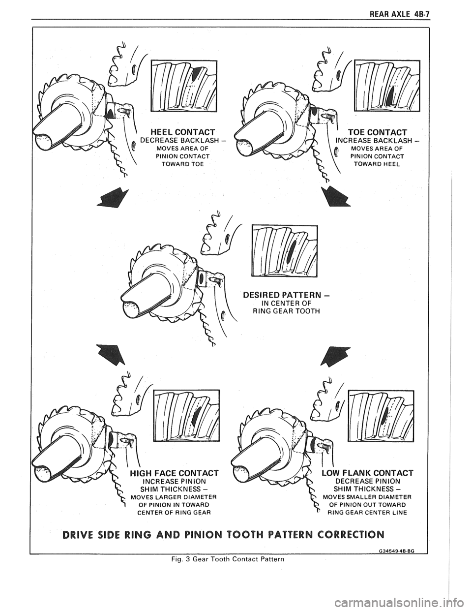
5. Observe
pattern on ring gear teeth and compare
with Fig. 3.
Effects of Increasing Load on Teeth Contact
Pattern
When "load" on ring and pinion gear is
increased, such as when car is accelerated forward
from standstill or from normal drive, the tooth contact
will tend to spread out and, under very heavy load, will
extend from near toe to near heel on the drive side. The
entire contact also tends to shift toward heel under
increasingly heavier loads and will become somewhat
broader with respect to tops and bottoms of teeth. The
patterns obtained by this tooth contact pattern test
approximate a light load and, for this reason, they will
extend only about halfway.
Page 278 of 1825
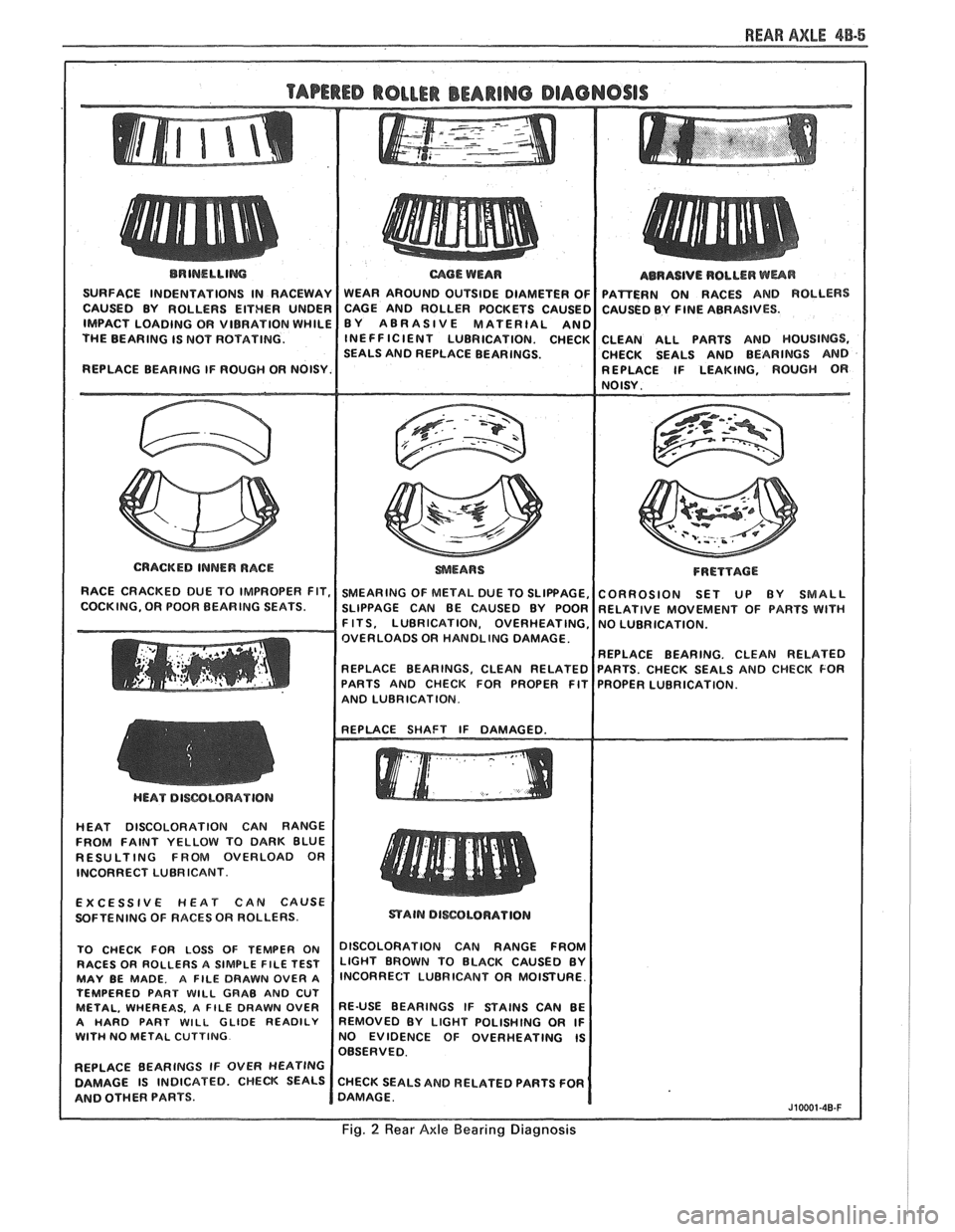
REAR AXLE 48-5
BRINELLIM
SURFACE INDENTATIONS IN RACEWAY
CAUSED BY ROLLERS EITHER UNDER
IMPACT LOADING OR VIBRATION WHILE
THE BEARING IS NOT ROTATING.
REPLACE BEARING IF ROUGH OR NOISY.
I
CRACKED INNER RACE
RACE CRACKED DUE TO IMPROPER FIT,
COCKING, OR POOR BEARING SEATS.
mOE WEAR
WEAR AROUND OUTSIDE DIAMETER OF
CAGE AND ROLLER POCKETS CAUSEC
BY ABRASIVE MATERIAL
AN0 INEFFICIENT LUBRICATION. CHECK
SEALS AND REPLACE BEARINGS.
SMEARING OF METAL DUE TO SLIPPAGE,
SLIPPAGE CAN BE CAUSED BY POOR
F ITS, LUBRICATION, OVERHEATING,
OVERLOADS OR HANDLING DAMAGE.
REPLACE BEARINGS. CLEAN RELATED
PARTS AND CHECK FOR PROPER FIT
AND LUBRICATION. ABRASIVE
ROLLER
WUR
PAmERN ON RACES AND ROLLERS
CAUSED BY FINE ABRASIVES.
CLEAN ALL PARTS AND HOUSINGS,
CHECK SEALS AND BEARINGS AND
REPLACE IF LEAKING, ROUGH
OR NOISY.
FRETTACE
CORROSION SET UP BY SMALL
RELATIVE MOVEMENT OF PARTS WlTH
NO LUBRICATION.
REPLACE BEARING. CLEAN RELATED
PARTS. CHECK SEALS AND CHECK FOR
PROPER LUBRICATION.
HEAT DISCOLORATION CAN RANGE
FROM FAINT YELLOW TO DARK BLUE
RESULTING FROM OVERLOAD OR
INCORRECT LUBRICANT.
EXCESSIVE
HEAT CAN CAUSE
SOFTENING OF RACES OR ROLLERS.
TO CHECK FOR LOSS OF TEMPER ON
DISCOLORATION CAN RANGE FFmM RACES OR ROLLERS A SIMPLE FILE TEST LIGHT BROWN TO BLACK CAUSED BY MAY BE MADE. A FILE DRAWN OVER A lNCORRECT LUBRICANT OR MOISTURE.
TEMPERED PART
WlLL GRAB AND CUT METAL, WHEREAS. A FILE DRAWN OVER RE-USE BEARINGS IF STAINS CAN BE
A HARD PART WILL GLIDE READILY REMOVED BY LIGHT POLISHING OR IF WITH NO METAL CUTTING NO EVIDENCE OF OVERHEATING IS
OBSERVED.
REPLACE BEARINGS IF OVER
HEATING
DAMAGE IS INDICATED. CHECK SEALS CHECK SEALS AND RELATED PARTS FOR
AND OTHER PARTS. DAMAGE.
J10001-40-F
Fig. 2 Rear Axle Bearing Diagnosis
Page 279 of 1825
48-6 REAR AXLE
The important thing to note is that the contact
pattern is centrally located up and down on the face of
the ring gear teeth.
Adjustments Affecting Tooth Contact
Two adjustments can be made which will affect
tooth contact pattern, backlash and position of drive
pinion in carrier. The effects of bearing pre-loads are
not readily apparent on (hand-loaded) tooth contact
pattern tests; however, these adjustments should be
within specifications before proceeding with backlash
and drive pinion adjustments.
Backlash is adjusted by means of the side bearing
adjusting shims, which moves the entire case and ring
gear assembly closer to, or farther from, the drive
pinion. Adjusting shims are also used to set side
bearing pre-load. The position of the drive pinion is
adjusted by increasing or decreasing the shim thickness
between the pinion head and inner race of rear bearing.
The shim is used in the rear axle case to compensate
for manufacturing tolerances. Increasing shim thickness
will move the pinion closer to centerline of
the ring gear. Decreasing shim thickness will move
pinion farther away from centerline of the ring gear.
Effects of Pinion Position on Tooth Pattern
When the drive pinion is too far away from
centerline of the ring gear, the pattern will be a high
heel contact on the drive side and high toe contact on
coast side (Fig.
3). Moving the pinion closer to
centerline of the ring gear by increasing shim thickness
will cause the high heel contact on drive side to lower
and move toward the toe; the high toe contact on coast
side will lower and move toward the heel.
When the pinion is too close to the centerline of
the ring gear, the pattern will be a low toe contact on
drive side and a low heel contact on the coast side.
Moving the pinion farther away from the ring gear by
decreasing shim thickness will cause low toe contact on
drive side to raise and move toward the heel; the low
heel contact on coast side will raise and move toward
the toe.
Page 280 of 1825
REAR AXLE 48-7
HEEL CONTACT
DECREASE BACKLASH -
MOVES AREA OF
PlNlON CONTACT
TOWARD TOE
TOE CONTACT CREASE BACKLASH MOVES AREA OF
PlNlON CONTACT
TOWARD HEEL
DESIRED PATTERN -
IN CENTER OF
RlNG GEAR TOOTH
MOVES LARGER DIAMETER ? OF PlNlON IN TOWARD
CENTER OF RlNG GEAR MOVES SMALLER
DIAMETER
OF PlNlON OUT TOWARD
RlNG GEAR CENTER LINE
DRIVE SIDE RING AND PINION TOOTH PATTERN CORRECTION
Fig. 3 Gear Tooth Contact Pattern