PONTIAC FIERO 1988 Service Repair Manual
Manufacturer: PONTIAC, Model Year: 1988, Model line: FIERO, Model: PONTIAC FIERO 1988Pages: 1825, PDF Size: 99.44 MB
Page 281 of 1825
4B-8 REAR AXLE
GENERAL lNFORMATlON
A universal joint connects the rear end of the
propeller shaft to a pinion flange, having a splined end
which fits over and drives the
hypoid pinion gear. The
housing is attached to the underbody through a center
bearing support. Inside the housing, an extension shaft
is splined to the drive pinion at the rear end, and to the
companion flange at the other end. Two pre-loaded
tapered roller bearings support the
hypoid pinion gear
in the carrier. The inner race of the rear bearing is a
light press fit on the pinion stem. The inner race of the
front bearing combines a light press fit to a close sliding
fit on the pinion flange end of the pinion stem. The
outer race of each bearing is pressed against a shoulder
recessed in the carrier. Tightening the pinion nut
compresses a collapsible spacer which bears against the
inner race of the front bearing and a shoulder on the
pinion stem. This spacer is used to enable accurate
bearing pre-load adjustment and
maintain a pre-load
on both front and rear pinion bearings. Adjustment of the
fore and aft position of the pinion is obtained by
placing
shims between the head of the drive pinion and
the rear pinion bearing.
The rear axle case is of
one-piece construction and is supported in the carrier
by two tapered roller side bearings. These are
pre-loaded by inserting
shims between the bearings and
the carrier. The rear axle case assembly is positioned
for proper ring gear to pinion backlash by varying the
shin1 thickness from side to side. The ring gear is bolted
to the case. Two side gears have splined bores for
driving the axle shafts. They are positioned to turn in
counterbored cavities in the case. The two rear axle
pinions have
smooth bores and are held in position by
a solid pinion cross shaft, mounted and locked in the
rear axle case. All four gears are in
mesh with each
other and because the pinion gears turn freely
on their
shaft, they act as idler gears when the rear wheels are
turning at different speeds. The pinions and side gears
are backed by steel thrust washers.
LIMITED-SLIP REAR AXLE
The operation of the Limited-Slip differential is
the same as the standard differential, except that there
is additional friction provided by the clutches or cones.
Under ordinary driving and cornering conditions, the
clutches or cones slip, allowing the outside wheel to
turn faster than the inner. Under poor traction
conditions, such as ice, snow, or loose gravel under one
driving wheel, the increased friction provided by the clutches
or cones increases the driving torque available
to the wheel with the better traction. The clutches or
cones are spring loaded to provide the increased
driving torque under extremely low traction
conditions.
Most rear axle service repairs can be made with
the rear axle assembly in the car, by raising the rear end
of the car with the rear axle hanging
on the shock
absorbers.
ON-VEHICLE SERVICE
CARRIER COVER AND GASKET
Remove or Disconnect
1. Having a container in place, remove cover bolts
and pry cover loose to drain lubricant.
2. Make sure both gasket sealing surfaces are clean.
Install or Connect
Use sealant
1052366 or cover gasket
only.
1. Torque cover bolts in a crosswise pattern to
insure uniform draw on gasket. Torque
27 N.m
(20 Ib.fr.).
2. Fill with lubricant to a level within 4.5mm (3116")
or filler plug hole. Refer to specifications for correct
lubricant usage and quantity.
Axle Shaft
a Remove or Disconnect
1. Raise car and remove wheel and brake drum.
2. Clean all dirt from area of carrier.
3. Remove bolts and differential carrier cover and
allow lubricant to drain.
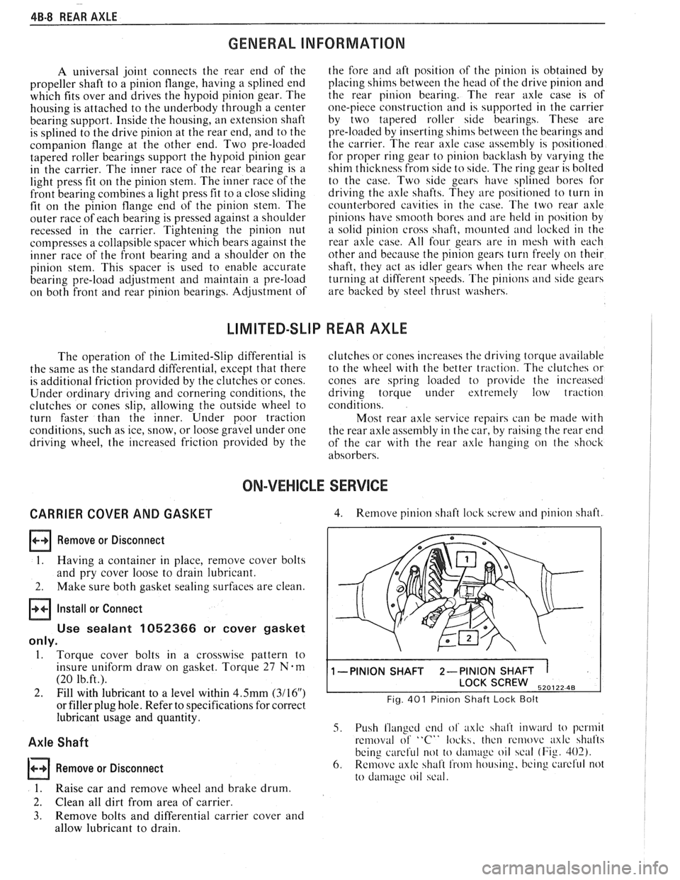
4. Remove pinion shaft lock screw and pinion shaft.
1 -PINION SHAFT 2-PINION SHAFT 1
SCREW 520122 48
Fig. 401 Pinion Shaft Lock Bolt
5. Push flanged end of axlc shalt inward to pcrmil
removal of "C" locks, thcn rcmovc axlc shafts
being
careful not to cl;uii~~gc oil scal (Fig. 402).
6. Remove axlc shaft from housing, bcing curcl'ul not
to
damage oil scal.
Page 282 of 1825
REAR AXLE 48-9
lnstall or Connect
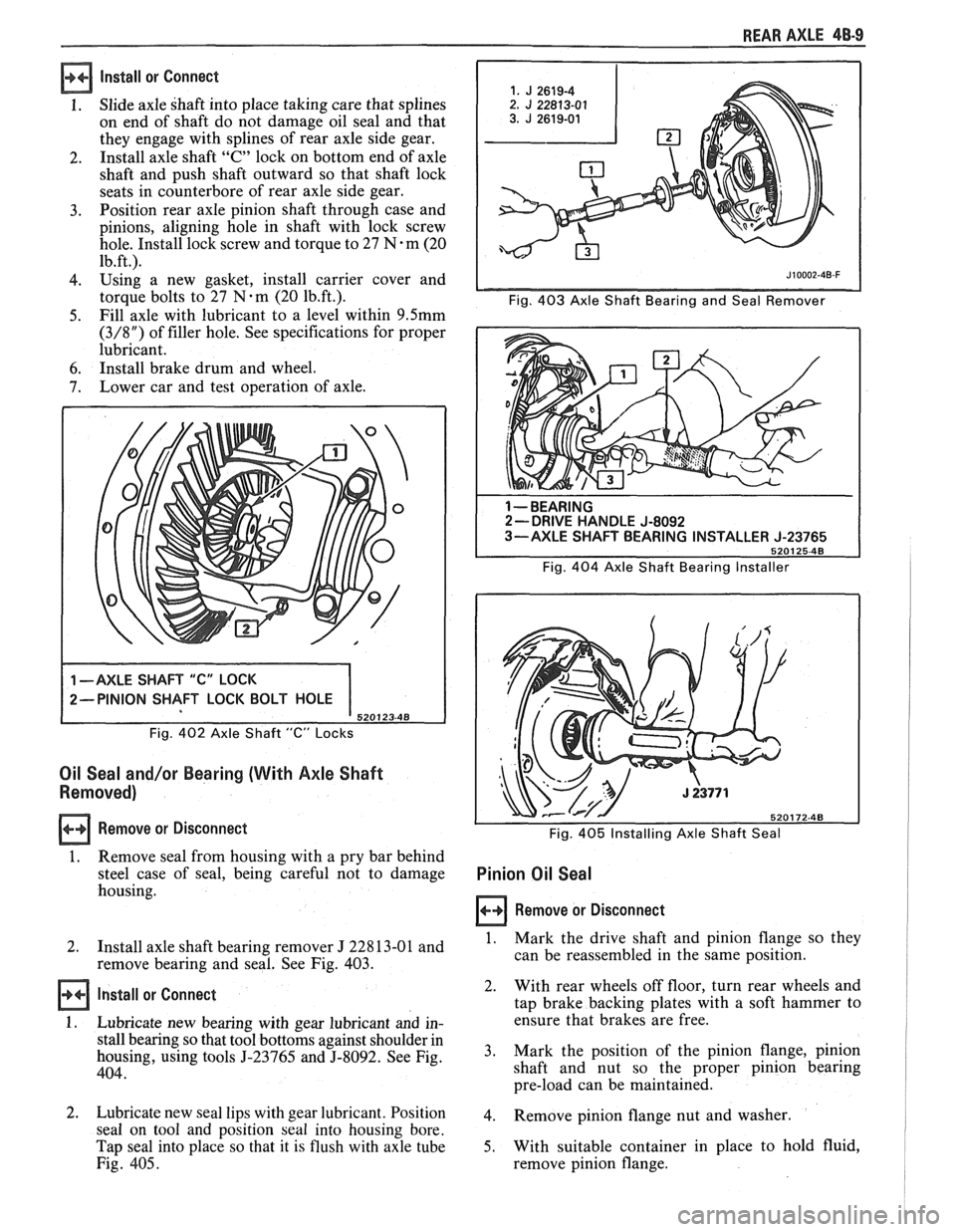
1. Slide axle shaft into place taking care that splines
on end of shaft do not damage oil seal and that
they engage with splines of rear axle side gear.
2. Install
axle shaft
"C" lock on bottom end of axle
shaft and push shaft outward so that shaft lock
seats in counterbore of rear axle side gear.
3. Position
rear axle pinion shaft through case and
pinions, aligning hole in shaft with lock screw
hole. Install lock screw and torque to 27
N-m (20
1b.ft.l
4. using a new gasket, install carrier cover and
torque
bolts to 27 N-m (20 1b.ft.). Fig. 403 Axle Shaft Bearing and Seal Remover
5. Fill
axle with lubricant to a level within 9.5mm
(3/8") of filler hole. See specifications for proper
lubricant.
6. Install brake drum and wheel.
7. Lower
car and test operation of axle.
Fig. 402 Axle Shaft "C" Locks
Oil Seal and/or Bearing (With Axle Shaft
Removed)
Remove or Disconnect
1. Remove seal
from housing with a pry bar behind
steel case of seal, being careful not to damage
housing.
1 --BEARING 2- DRIVE HANDLE J-8092
3-AXLE SHAFT BEARING INSTALLER J-23765
5201 25-48
Fig. 404 Axle Shaft Bearing Installer
Fig.
405 Installing Axle Shaft Seal
Pinion Oil Seal
Remove or Disconnect
I
2.
Install axle shaft bearing remover J 22813-01 and 1. Mark the drive shaft and pinion flange so they I
remove bearing and seal. See Fig. 403. can
be reassembled in the same position. I
Install or Connect
1. Lubricate new bearing with gear lubricant and in-
stall bearing so that tool bottoms against shoulder in
housing, using tools
5-23765 and 5-8092. See Fig.
404.
2. Lubricate new seal lips with gear lubricant. Position
seal on tool and position
seal into housing bore.
Tap seal into place so that it is flush with axle tube
Fig. 405. 2.
With rear
wheels off floor, turn rear wheels and
tap brake backing plates with a soft hammer to
ensure that brakes are free.
3. Mark
the position of the pinion flange, pinion
shaft and nut so the proper pinion bearing
pre-load can be maintained.
4. Remove pinion flange nut and washer.
5. With suitable container in place to hold fluid,
remove pinion flange.
Page 283 of 1825
48-10 REAR AXLE
6. Remove oil seal by driving it out of carrier with
a blunt chisel. Do not damage carrier. Discard
seal,
7. Examine seal surface of pinion flange for tool
marks, nicks, or damage. If damaged, replace
flange as outlined under Pinion Flange
Replacement.
8. Examine carrier bore and remove any burrs that
might cause leaks around the O.D. of the seal.
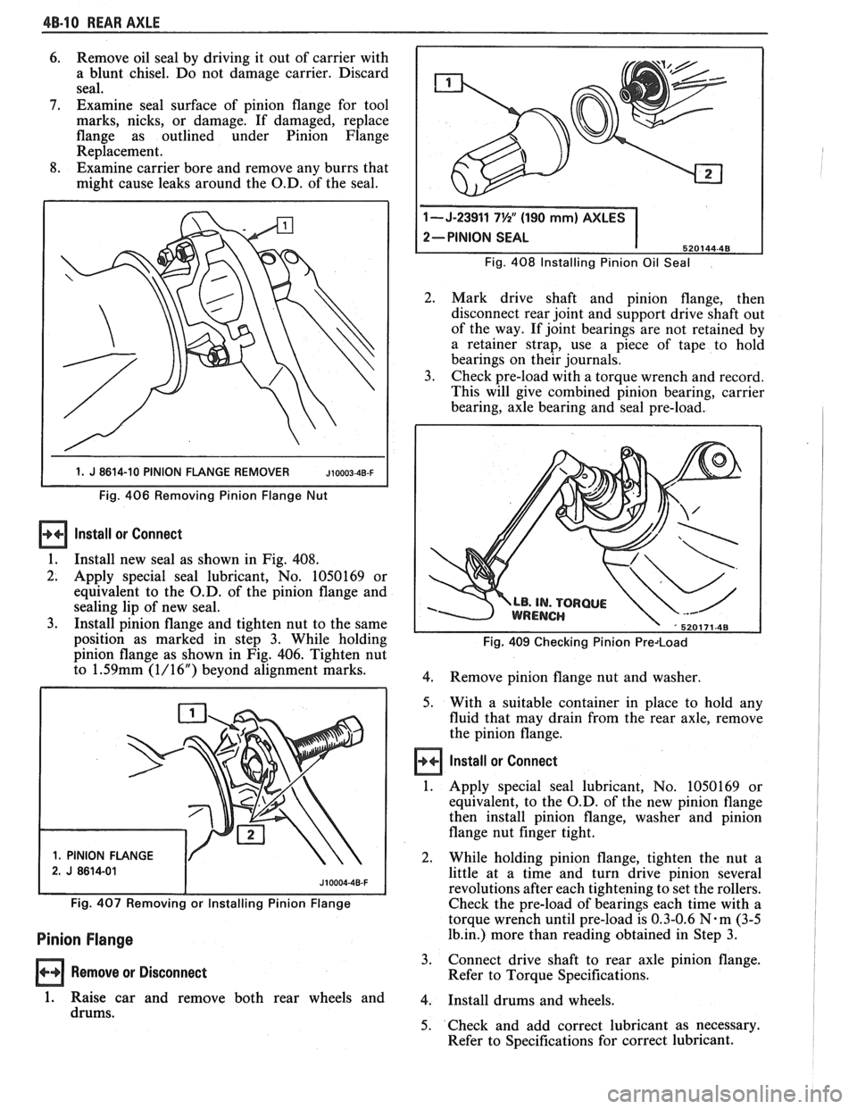
1 1. J 8614-10 PINION FLANGE REMOVER JIOOO~-~B-F I
Fig. 406 Removing Pinion Flange Nut
Install ar Connect
1.
Install new seal as shown in Fig. 408.
2. Apply special seal lubricant, No. 1050169 or
equivalent to the O.D. of the pinion flange and
sealing lip of new seal.
3. Install pinion flange and tighten nut to the same
position as marked in step 3. While holding
pinion flange as shown in Fig. 406. Tighten nut
to
1.59mm (1/16") beyond alignment marks.
1. PINION FLANGE Fig.
408 Installing Pinion
Oil Seal
2. Mark drive shaft and pinion flange, then
disconnect rear joint and support drive shaft out
of the way. If joint bearings are not retained by
a retainer strap, use a piece of tape to hold
bearings on their journals.
3. Check pre-load with a torque wrench and record.
This will give combined pinion bearing, carrier
bearing, axle bearing and seal pre-load.
Fig. 409 Checking Pinion Predoad
4.
Remove pinion flange nut and washer.
5. With a suitable container in place to hold any
fluid that may drain from the rear axle, remove
the pinion flange.
Install or Connect
1. Apply special seal lubricant, No. 1050169 or
equivalent, to the O.D. of the new pinion flange
then install pinion flange, washer and pinion
flange nut finger tight.
2. While holding pinion flange, tighten the nut a
little at a time and turn drive pinion several
revolutions after each tightening to set the rollers.
Fig. 407 Removing or Installing Pinion Flange Check the pre-load of bearings each time with a
torque wrench until pre-load is 0.3-0.6
N-m (3-5
Pinion Flange 1b.in.) more than reading obtained in Step 3.
Remove or Disconnect 3.
Connect drive shaft to rear axle pinion flange.
Refer to Torque Specifications.
1. Raise car and remove both rear wheels and 4. Install drums and wheels.
drums. 5. Check and add correct lubricant as necessary.
Refer to Specifications for correct lubricant.
Page 284 of 1825
REAR AXLE 48-1 1
Rear Wheel Bolt
Remove or Disconnect 1.
1. Raise vehicle on hoist allowing axle to hang
freely. 2.
2. Remove
wheel, tire and brake drum.
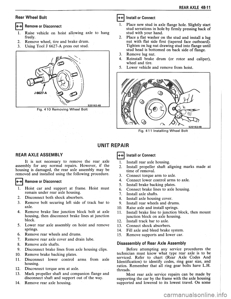
3. Using Tool J 6627-A press out stud.
Fig. 4 10 Removing Wheel Bolt
REAR AXLE ASSEMBLY
Install or Connect
Fig. 4 11 Installing Wheel Bolt
UNIT REPAIR
Remove or Disconnect
Place new stud in axle flange hole. Slightly start
stud serrations in hole by firmly pressing back of
stud with your hand.
Place a flat washer on the stud and install a lug
nut with flat side first (tapered face outboard).
Tighten on lug nut drawing stud into flange until
stud head is bottomed on back side of flange.
Remove lug nut.
Reinstall brake drum (or rotor and caliper),
wheel and tire.
Lower vehicle and remove from hoist.
It is not necessary to remove the rear axle
assembly for any normal repairs. However, if the
housing is damaged, the rear axle assembly may be
removed and installed using the following procedure.
Hoist car and support at frame. Hoist must
remain under rear axle housing.
Disconnect both shock absorbers.
Remove bolt securing left side of track bar to
axle.
Remove brake line junction block bolt at axle
housing, then disconnect brake lines at junction
block.
Lower rear axle assembly on hoist and remove
springs.
Remove rear wheels and drums.
Remove rear axle cover and drain lube.
Remove axle shafts.
Disconnect brake lines from axle housing clips.
Remove brake backing plates.
Disconnect lower control arms from axle
housing.
Disconnect torque arm at axle.
Mark propeller shaft and companion flange and
disconnect shaft and support out of the way.
Remove rear axle housing.
Install or Connect
Install rear axle housing.
Install propeller shaft aligning marks made at
time of removal.
Connect torque arm to axle.
Connect lower control arms to axle.
Install brake backing plates.
Connect brake lines to axle housing.
Install axle shafts.
Install axle housing cover.
Install rear wheels and drums.
Raise axle and install springs.
Install brake line to junction block, then mount
junction block on axle housing.
Install track bar to axle.
Connect shock absorbers.
Fill axle and bleed brake system.
Remove supports and lower car.
Disassembly of Rear Axle Assembly
Before attempting any service procedures the
technician must know what type rear axle is to be
serviced. Refer to chart (Rear Axle Codes And
Identification) to identify codes, ring gear size, and
ratios. Remember that all ring gear bolts have L.H.
threads.
Most rear axle service repairs can be made by
supporting the car by the frame with the axle housing
supported and lowered to its lowest travel. On some
Page 285 of 1825
48-1 2 REAR AXLE
models it may be necessary to disconnect shock
absorbers to obtain additional clearance. When doing
this, do not allow the rear brake hose to become kinked
or stretched.
Lubricant may be drained by backing out all
cover bolts and breaking cover loose at the bottom.
If the rear axle housing is removed for any reason,
rear axle service can be performed on the bench.
When a new ring gear and pinion is installed, the
owner should be advised not to accelerate rapidly or
exceed
50 mph for the first 50 miles of driving.
Case Assembly
Remove or Disconnect
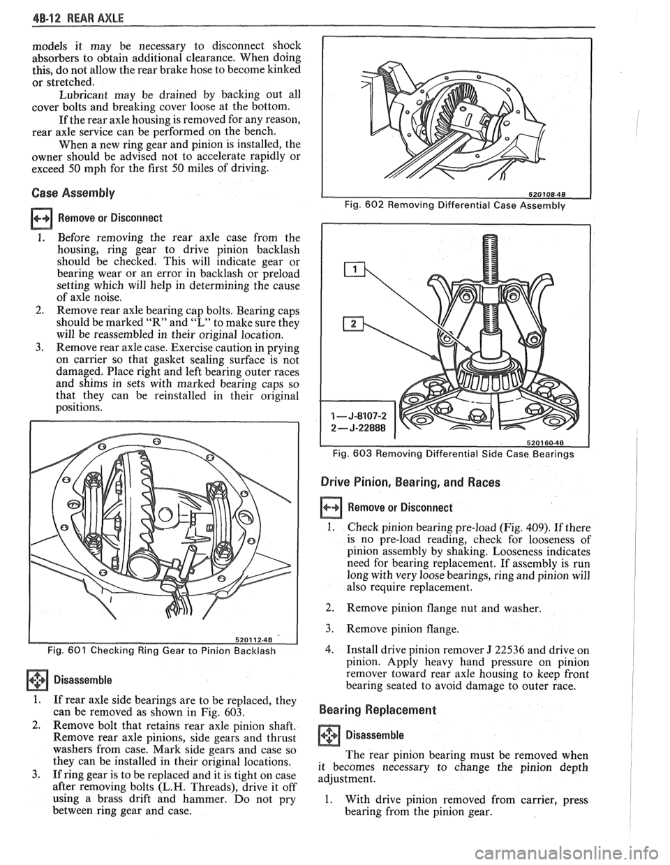
1. Before removing the rear axle case from the
housing, ring gear to drive pinion backlash
should be checked. This will indicate gear or
bearing wear or an error in backlash or preload
setting which will help in determining the cause
of axle noise.
2. Remove rear axle bearing cap bolts. Bearing caps
should be marked
"It" and "L" to make sure they
will be reassembled in their original location.
3. Remove rear axle case. Exercise caution in prying
on carrier so that gasket sealing surface is not
damaged. Place right and left bearing outer races
and shims in sets with marked bearing caps so
that they can be reinstalled in their original
positions.
Fig. 603 Removing Differential Side Case Bearings
Drive Pinion, Bearing, and Races
a Remove or Disconnect
1. Check pinion bearing pre-load (Fig. 409). If there
is no pre-load reading, check for looseness of
pinion assembly by shaking. Looseness indicates
need for bearing replacement. If assembly is run
long with very loose bearings, ring and pinion will
also require replacement.
Fig. 601 Checking Ring Gear to Pinion Backlash
Disassemble
1. If rear axle side bearings are to be replaced, they
can be removed as shown in Fig. 603.
2. Remove bolt that retains rear axle pinion shaft.
Remove rear axle pinions, side gears and thrust
washers from case. Mark side gears and case so
they can be installed in their original locations.
3. If ring gear is to be replaced and it is tight on case
after removing bolts
(L.H. Threads), drive it off
using a brass drift and hammer. Do not pry
between ring gear and case. 2.
Remove pinion flange
nut and washer.
3. Remove pinion flange.
4. Install drive pinion remover J 22536 and drive on
pinion. Apply heavy hand pressure on pinion
remover toward rear axle housing to keep front
bearing seated to avoid damage to outer race.
Bearing Replacement
I Disassemble
The rear pinion bearing must be removed when
it becomes necessary to change the pinion depth
adjustment.
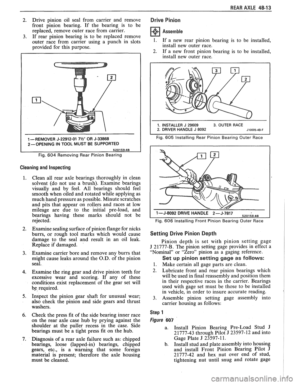
1. With drive pinion removed from carrier, press
bearing from the pinion gear.
Page 286 of 1825
REAR AXLE 48-13
2. Drive
pinion oil seal from carrier and remove
front pinion bearing. If the bearing is to be
replaced, remove outer race from carrier.
3. If rear pinion bearing is to be replaced remove
outer race from carrier using a punch in slots
provided for this purpose.
1 -REMOVER J-22912-01 7%" OR J-33868
2-OPENING IN TOOL MUST BE SUPPORTED
Fig.
604 Removing Rear Pinion Bearing
Cleaning and Inspecting
1. Clean
all rear axle bearings thoroughly in clean
solvent (do not use a brush). Examine bearings
visually and by feel. All bearings should feel
smooth when oiled and rotated while applying as
much hand pressure as possible. Minute scratches
and pits that appear on rollers and races at low
mileage are due to the initial pre-load, and
bearings having these marks should not be
rejected.
2. Examine sealing surface of pinion flange for nicks
burrs, or rough tool marks which would cause
damage to the seal and result in an oil leak.
Replace if damaged.
'
3. Examine carrier bore and remove any burrs that
might cause leaks around the O.D. of the pinion
seal.
4. Examine the ring gear and drive pinion teeth for
excessive wear and scoring. If any of these
conditions exist replacement of the gear set will
bs required.
5. Inspect the pinion gear shaft for unusual wear;
also check the pinion and side gears and thrust
washers.
6. Check the press fit of the side bearing inner race
on the rear axle case hub by prying against the
shoulder at the puller recess in the case. Side
bearings must be a tight press fit on the hub.
7. Diagnosis of a rear axle failure such as: chipped
bearings, loose (lapped-in) bearings, chipped
gears, etc., is a warning that some foreign
material is present; therefore the axle housing
must be cleaned.
Drive Pinion
Assemble
I. If a new rear pinion bearing is to be installed,
install new outer race.
2. If a new front pinion bearing is to be installed,
install new outer race.
Fig. 605 Installing Rear Pinion Bearing Outer Race
1- J-8092 DRIVE H-,.wb- 6
Fig. 606 Installing Front Pinion Bearing Outer Race
Setting Drive Pinion Depth
Pinion depth is set with pinion setting gage
J 21777-B. The pinion setting gage provides in effect a
"Nominal" or "Zero" pinion as a gaging reference.
Set up pinion setting gage as follows:
1. Make certain all gage parts are clean.
2. Lubricate front and rear pinion bearings which
will be used in final reassembly and position them
in their respective races in the carrier. Bearings
used with gage set must be those to be installed
in vehicle, in order to insure accurate reading.
3. Assemble pinion setting gage assembly into
carrier housing as follows:
Step 1
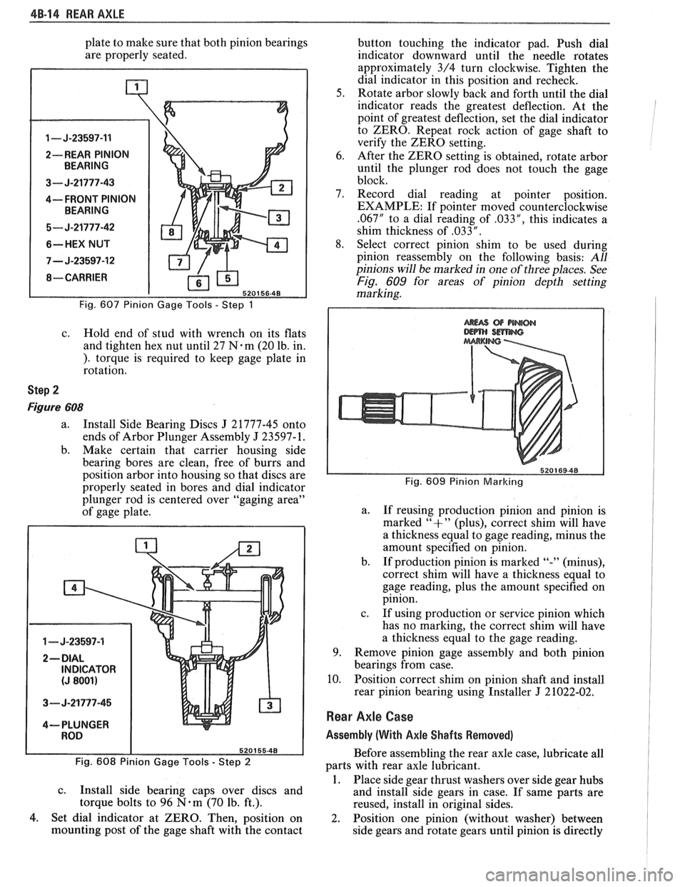
Figure 607
a.
Install Pinion Bearing Pre-Load Stud J
21777-43 through Pilot J 23597-12 and into
Gage Plate
J 23597- 11.
b. Install stud and plate assembly into housing
and install Front Pinion Bearing Pilot
J
21777-42 and hex nut over end of stud,
tightening nut until snug and rotate gage
Page 287 of 1825
4B-14 REAR AXLE
plate to make sure that both pinion bearings
are properly seated.
1 - J-23597-11
2-- REAR PINION
3--- J-21777-43
4---- FRONT PINION
5- J-21777-42
6-HEX NUT
7 - J-23597-12
Fig. 607 Pinion Gage Tools - Step 1
c. Hold end of stud with wrench on its flats
and tighten hex nut until 27
N.m (20 lb. in.
). torque is required to keep gage plate in
rotation.
Step 2
Figure 608
a. Install Side Bearing Discs J 21777-45 onto
ends of Arbor Plunger Assembly
J 23597- 1.
b. Make certain that carrier housing side
bearing bores are clean, free of burrs and
position arbor into housing so that discs are
properly seated in bores and dial indicator
plunger rod is centered over "gaging area"
of gage plate.
1 - J-23597-4
3- J-21777-45
4--- PLUNGER
Fig. 608 Pinion Gage Tools
- Step 2
c.
Install side bearing caps over discs and
torque bolts to 96
N-m (70 lb. ft.).
4. Set dial indicator at ZERO. Then, position on
mounting post of the gage shaft with the contact button
touching the indicator pad. Push dial
indicator downward until the needle rotates
approximately 3/4 turn clockwise. Tighten the
dial indicator in this position and recheck.
5. Rotate arbor slowly back and forth until the dial
indicator reads the greatest deflection. At the
point of greatest deflection, set the dial indicator
to ZERO. Repeat rock action of gage shaft to
verify the ZERO setting.
6. After the ZERO setting is obtained, rotate arbor
until the plunger rod does not touch the gage
block.
7. Record dial reading at pointer position.
EXAMPLE: If pointer moved counterclockwise
.067" to a dial reading of .033", this indicates a
shim thickness of
,033 " .
8. Select correct pinion shim to be used during
pinion reassembly on the following basis:
All
pinions will be marked in one of three places. See
Fig. 609 for areas of pinion depth setting
marking.
Fig. 609 Pinion Marlcing
a.
If reusing production pinion and pinion is
marked
"+" (plus), correct shim will have
a thickness equal to gage reading, minus the
amount specified on pinion.
b. If production pinion is marked
"-" (minus),
correct shim will have
a thickness equal to
gage reading, plus the amount specified on
pinion.
c. If using production or service pinion which
has no marking, the correct shim will have
a thickness equal to the gage reading.
9. Remove pinion gage assembly and both pinion
bearings from case.
10. Position correct shim on pinion shaft and install
rear pinion bearing using Installer
J 21022-02.
Rear Axle Case
Assembly (With Axle Shafts Removed)
Before assembling the rear axle case, lubricate all
parts with rear axle lubricant.
1. Place side gear thrust washers over side gear hubs
and install side gears in case. If same parts are
reused, install in original sides.
2. Position one pinion (without washer) between
side gears and rotate gears until pinion is directly
Page 288 of 1825
REAR AXLE 48-15
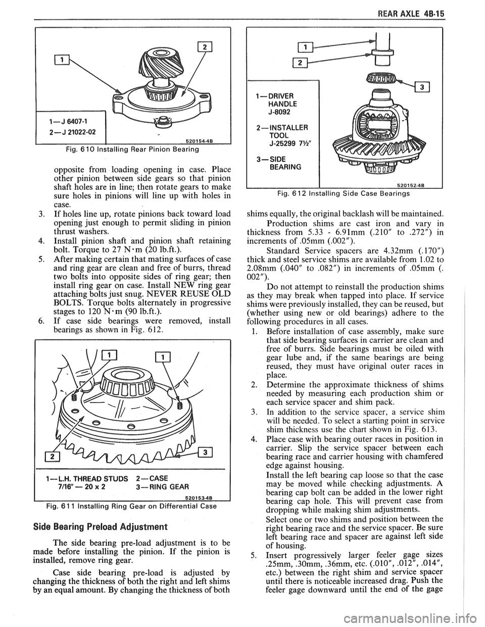
Fig. 6 10 lnstalling Rear Pinion Bearing
opposite from loading opening in case. Place
other pinion between side gears so that pinion
shaft holes are in line; then rotate gears to make
sure holes in pinions will line up with holes in
case.
3. If holes line up, rotate pinions back toward load
opening just enough to permit sliding in pinion
thrust washers.
4. Install pinion shaft and pinion shaft retaining
bolt. Torque to 27
N.m (20 1b.ft.).
5. After making certain that mating surfaces of case
and ring gear are clean and free of burrs, thread
two bolts into opposite sides of ring gear; then
install ring gear on case. Install NEW ring gear
attaching bolts just snug. NEVER REUSE OLD
BOLTS. Torque bolts alternately in progressive
stages to 120
N.m (90 1b.ft.).
6. If case side bearings were removed, install
bearings as shown in Fig. 612.
1-L.H. THREAD STUDS 2-CASE 711 6" ---- 20 x 2 3-RING GEAR
Fig.
6 1 1 lnstalling Ring Gear on Differential Case
Side Bearing Preload Adjustment
The side bearing pre-load adjustment is to be
made before installing the pinion. If the pinion is
installed, remove ring gear.
Case side bearing pre-load is adjusted by
changing the thickness of both the right and left shims
by an equal amount. By changing the thickness of both
Fig. 6 12 Installing Side Case Bearings
shims equally, the original backlash will be maintained.
Production shims are cast iron and vary in
thickness from
5.33 - 6.91mm (.210" to 272") in
increments of
.05mm (.002").
Standard Service spacers are 4.32mm (.17OU)
thick and steel service shims are available from 1.02 to
2.08mm (.040" to ,082") in increments of .05mm (.
002").
Do not attempt to reinstall the production shims
as they may break when tapped into place. If service
shims were previously installed, they can be reused, but
(whether using new or old bearings) adhere to the
following procedures in all cases.
1. Before installation of case assembly, make sure
that side bearing surfaces in carrier are clean and
free of burrs. Side bearings must be oiled with
gear lube and, if the same bearings are being
reused, they must have original outer races in
place.
2. Determine the approximate thickness of shims
needed by measuring each production shim or
each service spacer and shim pack.
3. In addition to the service spacer, a service shin1
will be needed. To select a starting point in service
shim thickness use the chart shown in
Fig. 613.
4. Place case with bearing outer races in position in
carrier. Slip the service spacer between each
bearing race and carrier housing with chamfered
edge against housing.
Install the left bearing cap loose so that the case
may be moved while checking adjustments. A
bearing cap bolt can be added in the lower right
bearing cap hole. This will prevent case from
dropping while making shim adjustments.
Select one or two shims and position between the
right bearing race and the service spacer. Be sure
left bearing race and spacer are against left side
of housing.
5. Insert progressively larger feeler gage sizes
.25mm, .30mm, .36mm, etc. (.01OU, .012", .014",
etc.) between the right shim and service spacer
until there is noticeable increased drag. Push the
feeler gage downward until the end of
the gage
Page 289 of 1825
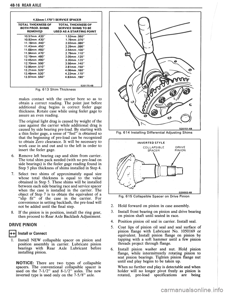
48-16 REAR AXLE
4.32mm (.170") SERVICE WACER
TOTAL THICKNESS OF TOTAL THICKNESS OF
BOTH PROD. SHIMS SERVICE SHIMS TO BE
REMOVED USED AS A STARTING POINT
Fig. 6 13 Shim Thickness
makes contact with the carrier bore so as to
obtain a correct reading. The point just before
additional drag begins is correct feeler gage
thickness. Rotate case while using feeler gage to
assure an even reading.
The original light drag is caused by weight of the
case against the carrier while additional drag is
caused by side bearing pre-load. By starting with
a thin feeler gage, a sense of "feel" is obtained so
that the beginning of pre-load can be recognized
to obtain Zero clearance. It will be necessary to
work case in and out and to the left in order to
insert the feeler gage.
6. Remove left bearing cap and shim from carrier.
The total shim pack needed (with no pre-load on
side bearings) is the feeler gage reading found in
Step
5 plus thickness of shims installed in Step 4.
7. Select two shims of approximately equal size
whose total thickness is equal to the value
obtained in Step
5. These shims will be installed
between each side bearing race and service spacer
when the case is installed in the carrier. The
object of Step 7 is to obtain the equivalent of a
"slip fit" of the case in the carrier. For
convenience in setting backlash, the pre-load will
not be added until the final step.
8. If the pinion is in position, install the ring gear,
then proceed to Rear Axle Backlash Adjustment.
DRIVE PINION
Install or Connect
1.
Install NEW collapsible spacer on pinion and
position assembly in carrier. Lubricate pinion
bearings with Rear Axle Lubricant before
installing pinion.
NOTICE: There are two types of collapsible
spacers. The conventional collapsible spacer is
used on the
7-1/2" and 8-1/2" axles. The new
inverted type is used only on the
7-5/8" axle.
Fig. 6 14 Installing Differential Adjusting Shims
COLLAPSIBLE DRIVE SPACER PINION I
Fig. 61 5 Collapsible Spacer on Drive Pinion
2.
Hold forward on pinion in case assembly.
3. Install front bearing on pinion and drive bearing
on pinion shaft until seated in race.
4. Position pinion oil seal in carrier. Install seal.
5. Coat lips of pinion oil seal and seal surface of
pinion flange with Lubricant No. 1050169 or
equivalent. Install pinion flange on pinion by
tapping with a soft hammer until a few pinion
threads project through flange.
6. Install pinion washer and nut. Hold pinion
flange, while intermittently rotating pinion to
seat pinion bearings. Tighten pinion flange nut
until end play begins to be taken up.
When no further end play is detectable and when
holder will no longer pivot freely as pinion is
rotated, pre-load specifications are being
Page 290 of 1825
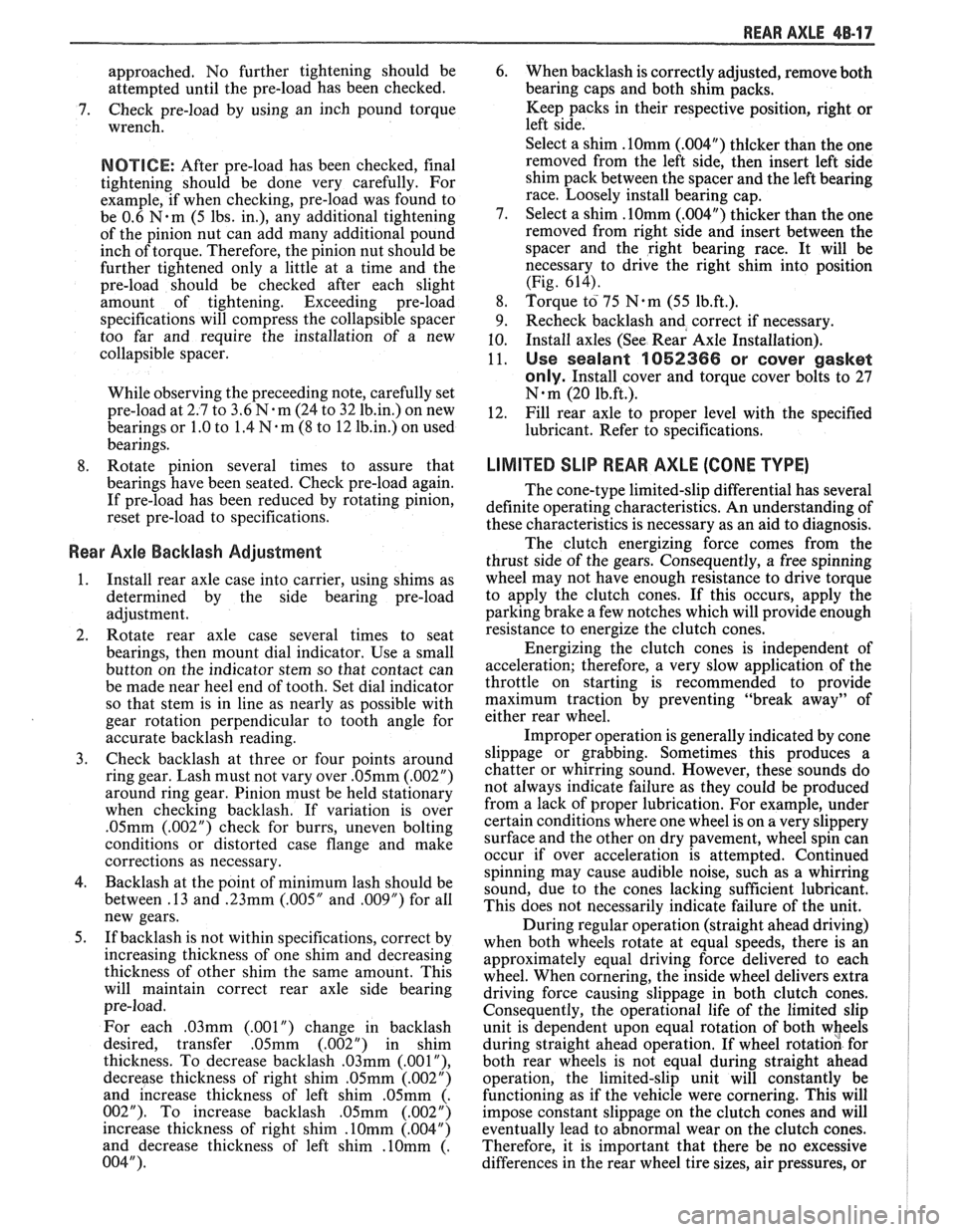
REAR AXLE 48-1 7
approached. No further tightening should be
attempted until the pre-load has been checked.
7. Check pre-load by using an inch pound torque
wrench.
NOTICE: After pre-load has been checked, final
tightening should be done very carefully. For
example, if when checking, pre-load was found to
be 0.6
N-m (5 lbs. in.), any additional tightening
of the pinion nut can add many additional pound
inch of torque. Therefore, the pinion nut should be
further tightened only a little at a time and the
pre-load should be checked after each slight
amount of tightening. Exceeding pre-load
specifications will compress the collapsible spacer
too far and require the installation of a new
collapsible spacer.
While observing the preceeding note, carefully set
pre-load at 2.7 to 3.6
N-m (24 to 32 1b.in.) on new
bearings or 1.0 to 1.4
N m (8 to 12 1b.in.) on used
bearings.
8. Rotate pinion several times to assure that
bearings have been seated. Check pre-load again.
If pre-load has been reduced by rotating pinion,
reset pre-load to specifications.
Rear Axle Backlash Adjustment
1. Install rear axle case into carrier, using shims as
determined by the side bearing pre-load
adjustment.
2. Rotate rear axle case several times to seat
bearings, then mount dial indicator. Use a small
button on the indicator stem so that contact can
be made near heel end of tooth. Set dial indicator
so that stem is in line as nearly as possible with
gear rotation perpendicular to tooth angle for
accurate backlash reading.
3. Check backlash at three or four points around
ring gear. Lash must not vary over
.05mm (.002")
around ring gear. Pinion must be held stationary
when checking backlash. If variation is over
.05mm (.002") check for burrs, uneven bolting
conditions or distorted case flange and make
corrections as necessary.
4. Backlash at the point of minimum lash should be
between .13 and
.23mm (.005" and ,009") for all
new gears.
5. If backlash is not within specifications, correct by
increasing thickness of one shim and decreasing
thickness of other shim the same amount. This
will maintain correct rear axle side bearing
pre-load.
For each
.03mm (.001") change in backlash
desired, transfer
.05mm (.002") in shim
thickness. To decrease backlash
.03mm (.00lU),
decrease thickness of right shim .05mm (.002")
and increase thickness of left shim .05mm (.
002 "). To increase backlash .05mm (.002 ")
increase thickness of right shim .10mm (.004")
and decrease thickness of left shim .10mm (.
004"). 6.
When backlash is correctly adjusted, remove both
bearing caps and both shim packs.
Keep packs in their respective position, right or
left side.
Select a shim
.10mm (.004") thicker than the one
removed from the left side, then insert left side
shim pack between the spacer and the left bearing
race. Loosely install bearing cap.
7. Select a shim
.10mm (.004") thicker than the one
removed from right side and insert between the
spacer and the right bearing race. It will be
necessary to drive the right shim into position
(Fig. 614).
8. Torque to 75 Nem (55 1b.ft.).
9. Recheck backlash
and correct if necessary.
10. Install axles (See Rear Axle Installation).
11.
Use sealant 1052366 or cover gasket
only.
Install cover and torque cover bolts to 27
N-m (20 1b.ft.).
12. Fill rear axle to proper level with the specified
lubricant. Refer to specifications.
LIMITED SLIP REAR AXLE (GONE TYPE)
The cone-type limited-slip differential has several
definite operating characteristics. An understanding of
these characteristics is necessary as an aid to diagnosis.
The clutch energizing force comes from the
thrust side of the gears. Consequently, a free spinning
wheel may not have enough resistance to drive torque
to apply the clutch cones. If this occurs, apply the
parking brake a few notches which will provide enough
resistance to energize the clutch cones.
Energizing the clutch cones is independent of
acceleration; therefore, a very slow application of the
throttle on starting is recommended to provide
maximum traction by preventing "break away" of
either rear wheel.
Improper operation is generally indicated by cone
slippage or grabbing. Sometimes this produces a
chatter or whirring sound. However, these sounds do
not always indicate failure as they could be produced
from a lack of proper lubrication. For example, under
certain conditions where one wheel is on
a very slippery
surface and the other on dry pavement, wheel spin can
occur if over acceleration is attempted. Continued
spinning may cause audible noise, such as a whirring
sound, due to the cones lacking sufficient lubricant.
This does not necessarily indicate failure of the unit.
During regular operation (straight ahead driving)
when both wheels rotate at equal speeds, there is an
approximately equal driving force delivered to each
wheel. When cornering, the inside wheel delivers extra
driving force causing slippage in both clutch cones.
Consequently, the operational life of the limited slip
unit is dependent upon equal rotation of both wheels
during straight ahead operation. If wheel rotation for
both rear wheels is not equal during straight ahead
operation, the limited-slip unit will constantly be
functioning as if the vehicle were cornering. This will
impose constant slippage on the clutch cones and will
eventually lead to abnormal wear on the clutch cones.
Therefore, it is important that there be no excessive
differences in the rear wheel tire sizes, air pressures, or