PONTIAC FIERO 1988 Service Repair Manual
Manufacturer: PONTIAC, Model Year: 1988, Model line: FIERO, Model: PONTIAC FIERO 1988Pages: 1825, PDF Size: 99.44 MB
Page 231 of 1825

Page 232 of 1825
TIRES AND WHEELS 3E-1
RES AND WHEELS
NOTICE: All wheel bolt and nut fasteners are important attaching parts in that they could affect the
performance of vital components and systems, and/or could result in major repair expense. They must be replaced
with one of the same part number or with an equivalent part if replacement becomes necessary. Do not use a
replacement part of lesser quality or substitute design. Torque values must be used as specified during reassembly
to assure proper retention of parts.
CONTENTS
Diagnosis ............................................... Section 3 Tire Repair ................................................... 3E-5
General Information .......................... ..... 3E-1 Waddle ........................................................ 3E-5
........ Replacement Tires ....................... ... 3E- 1 Measuring Wheel Runout ............................ 3E-6
P-Metric Tires ...................... .. ................... 3E-2 Spare Tire ...................................................... 3E-6 ................................................ Tire Placard 3E-2 Match Mounting ......................................... 3E-7
.......................................................... Wheels 3E-2 Balancing Tire and Wheel ............................ 3E-7
....................... Maintenance and Adjustments .............. 3E-2 General Balance Precautions 3E-7 ...................................... Wheel Repair .............................................. 3E-2 Off-Car Balancing 3E-8 .............................. Metric Wheel Nuts and Studs .................... .. 3E-3 On-Car Balancing .. ...... 3E-8
......................................... Inflation of Tires ........................................ 3E-3 Wheel Weights 3E-8 .................... Tire Rotation ........................... ...... . 3E-3 Correcting Non-Uniform Tires 3E-8 .......................... Tire Chain Usage ........................................ 3E-4 Aluminum Wheel Cleaning 3E-9 Aluminum Wheel Hub Cap ......................... 3E-9 Service Operations ..................................... 3E-4 Aluminum Wheel Porosity Repair .............. 3E-9 ......................... Wheel Removal .... .......... 3E-4 Aluminum Wheel Refinishing ...................... 3E-9 Tire Mounting and Dismounting ................. 3E-5 Wheel Nut Torque 3E-10 ......................................
GENERAL INFORMATION ~t is recommended that new tires be installed in
pairs on the same axle. If it is necessary to replace only
The tires and are one tire, it should be paired with the tire having the
designed to operate satisfactorily with loads up to and
most tread, to equalize braking traction. including the full rated load capacity when inflated to
Although they may appear different in tread
the recommended inflation pressures.
design, tires built by different manufacturers with
Correct tire pressures, wheel alignment and identical TPC specification numbers, can be
driving techniques have an important influence on tire
intermixed on the same car. life. Heavy cornering, excessive rapid acceleration, and
heavy braking will increase tire wear.
REPLACEMENT TIRES
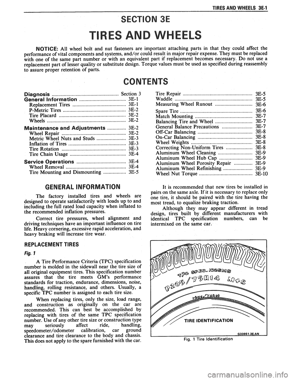
Fig. 1
A Tire Performance Criteria (TPC) specification
number is molded in the sidewall near the tire size of
all original equipment tires. This specification number
assures that the tire meets
GM's performance
standards for traction, endurance, dimensions, noise,
handling, rolling resistance, and others. Usually, a
specific TPC number is assigned to each tire size.
When replacing tires, only the size, load range,
and construction as originally on the car are
recommended. This can best be accomplished by
replacing with tires of the same TPC specification
number. Use of any other tire size or construction type
may seriously affect ride, handling,
speedometer/odometer calibration, car ground
clearance and tire clearance to the body and chassis.
This does not apply to the spare furnished with the car.
v// TIRE IDENTIFICATION
Fig. 1 Tire Identification
Page 233 of 1825
3E.2 TIRES AND WHEELS
P-METRIC SIZED TIRES
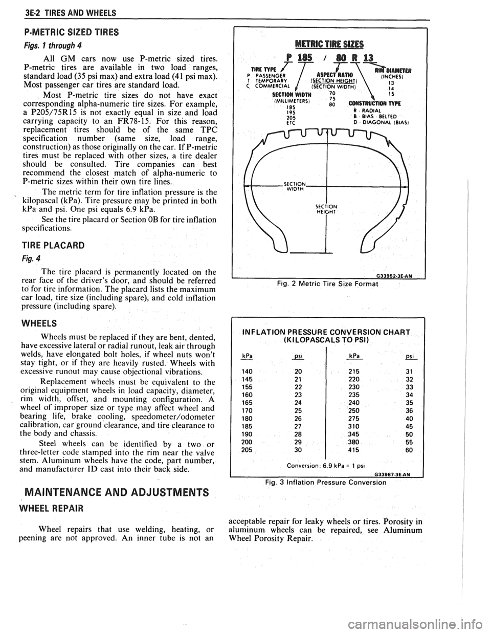
Figs. 1 through 4
All GM cars now use P-metric sized tires.
P-metric tires are available in two load ranges,
standard load
(35 psi max) and extra load (41 psi max).
Most passenger car tires are standard load.
Most P-metric tire sizes do not have exact
corresponding alpha-numeric tire sizes. For example,
a
P205/75R15 is not exactly equal in size and load
carrying capacity to an
FR78-15. For this reason,
replacement tires should be of the same TPC
specification number (same size, load range,
construction) as those originally on the car. If P-metric
tires must be replaced with other sizes, a tire dealer
should be consulted. Tire companies can best
recommend the closest match of alpha-numeric to
P-metric sizes within their own tire lines.
The metric term for tire inflation pressure is the
kilopascal
(kPa). Tire pressure may be printed in both
kPa and psi. One psi equals 6.9 kPa.
See the tire placard or Section OB for tire inflation
specifications.
TlRE PLACARD
Fig. 4
The tire placard is permanently located on the
rear
face of the driver's door, and should be referred
to for tire information. The placard lists the maximum
car load, tire size (including spare), and cold inflation
pressure (including spare).
WHEELS
Wheels must be replaced if they are bent, dented,
have excessive lateral or radial
runout, leak air through
welds, have elongated bolt holes, if wheel nuts won't
stay tight, or if they are heavily rusted. Wheels with
excessive
runout may cause objectional vibrations.
Replacement wheels must be equivalent to the
original equipment wheels in load capacity, diameter,
rim width, offset, and mounting configuration.
A
wheel of improper size or type may affect wheel and
bearing life, brake cooling,
speedometer/odometer
calibration, car ground clearance, and tire clearance to
the body and chassis.
Steel wheels can be identified by a two or
three-letter code stamped into the rim near the valve
stem. Aluminum wheels have the code, part number,
and manufacturer
ID cast into their back side.
MAINTENANCE AND ADJUSTMENTS
WHEEL REPAIR
Wheel repairs that use welding, heating, or
peening are not approved. An inner tube is not an
Fig. 2 Metric Tire Size Format
INFLATION PRESSURE CONVERSION CHART (KI LOPASCALS TO PSI)
Fig. 3 Inflation Pressure Conversion
acceptable repair for leaky wheels or tires. Porosity in
aluminum wheels can be repaired, see Aluminum
Wheel Porosity Repair.
Page 234 of 1825
TIRES AND WHEELS 3E-3
METRIC WHEEL NUTS AND STUDS
Some models use metric wheel nuts and wheel
studs. The nut will have the word "metric" stamped on
its face and the stud will have the letter
"M" stamped
into the threaded end. The word "metric" is stamped
on its head.
The thread size of the metric wheel nuts and
wheel studs are
"MI2 x 1.5". These stand for:
M = Metric
12
= Diameter in millimeters
1.5
= Millimeters per thread
If a broken stud is found, see Section 3C (Front
Suspension) or Section 3D (Rear Suspension) for
replacement procedure.
INFLATION OF TIRES
The pressure recommended for any model is
carefully calculated to give a satisfactory ride,
handling, tread life and load carrying capacity.
Tire pressure, with tires cold, (after car has set for
three hours or more, or driven less than one mile)
should be checked monthly or before any extended trip
and set to the specifications on the tire placard located
on rear face of driver's door. Tire inflation pressure is
also given in Section OB.
Valve caps or extensions should be on the valves
to keep dust and water out.
1. For sustained driving at speeds up to 85
mph (140 km/h), in countries where such
speeds are allowed by law, your tires should be set
at the pressures recommended on your tire
placard.
Sustained driving at speeds
faster than
85 mph (140 km/h), where
permitted
by law, is not advised unless
your car has special high speed tires available
from many tire dealers.
2. Tire pressures may increase as much as 6 psi
when hot.
3. Higher
than recommended pressure can cause:
o Hard ride
o Tire bruising or carcass damage
Rapid tread wear at center of tire
4. Lower
than
recommended pressure can cause:
@ Tire squeal on turns
@ Hard steering
o Rapid and uneven wear on the edges of the
tread
Tire rim bruises and rupture
e Tire cord breakage
o High tire temperatures
o Reduced handling
High fuel consumption
5. Unequal pressure on same axle can cause:
Uneven braking
o Steering lead
o Reduced handling
e Swerve on acceleration
TlRE ROTATION
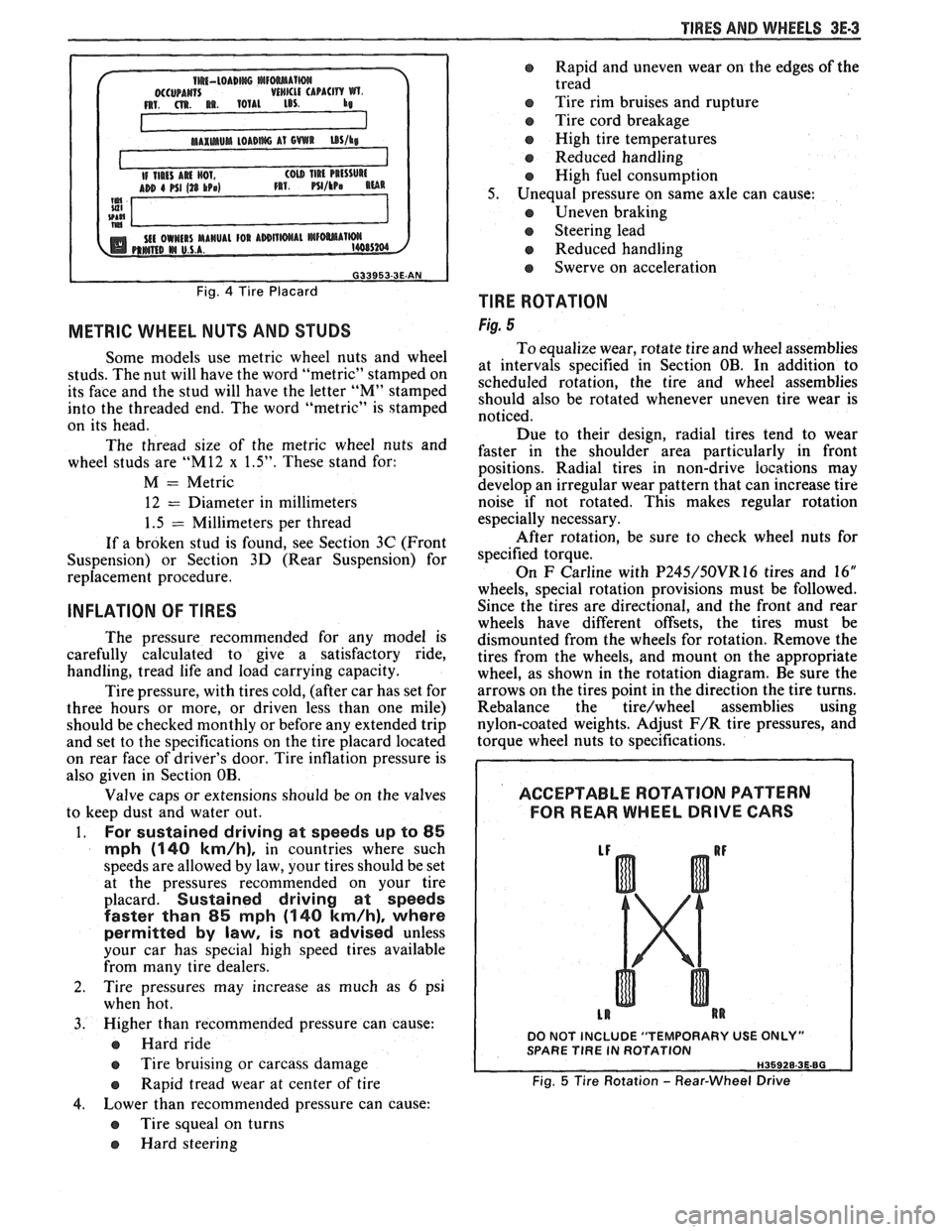
Fig. 5
To equalize wear, rotate tire and wheel assemblies
at intervals specified in Section OB. In addition to
scheduled rotation, the tire and wheel assemblies
should also be rotated whenever uneven tire wear is
noticed.
Due to their design, radial tires tend to wear
faster in the shoulder area particularly in front
positions. Radial
tires in non-drive
iocations may
develop an irregular wear pattern that can increase tire
noise if not rotated. This makes regular rotation
especially necessary.
After rotation, be sure to check wheel nuts for
specified torque.
On
F Carline with P245/50VR16 tires and 16"
wheels, special rotation provisions must be followed.
Since the tires are directional, and the front and rear
wheels have different offsets, the tires must be
dismounted from the wheels for rotation. Remove the
tires from the wheels, and mount on the appropriate
wheel, as shown in the rotation diagram. Be sure the
arrows on the tires point in the direction the tire turns.
Rebalance the
tire/wheel assemblies using
nylon-coated weights. Adjust
F/R tire pressures, and
torque wheel nuts to specifications.
ACCEPTABLE ROTATION PATTERN
FOR REAR WHEEL
DRIVE GARS
DO NOT INCLUDE "TEMPORARY USE ONLY" SPARE TlRE IN ROTATION
Fig. 5 Tire Rotation - Rear-Wheel Drive
Page 235 of 1825
3E.4 TIRES AND WHEELS
TIRE CHAIN USAGE
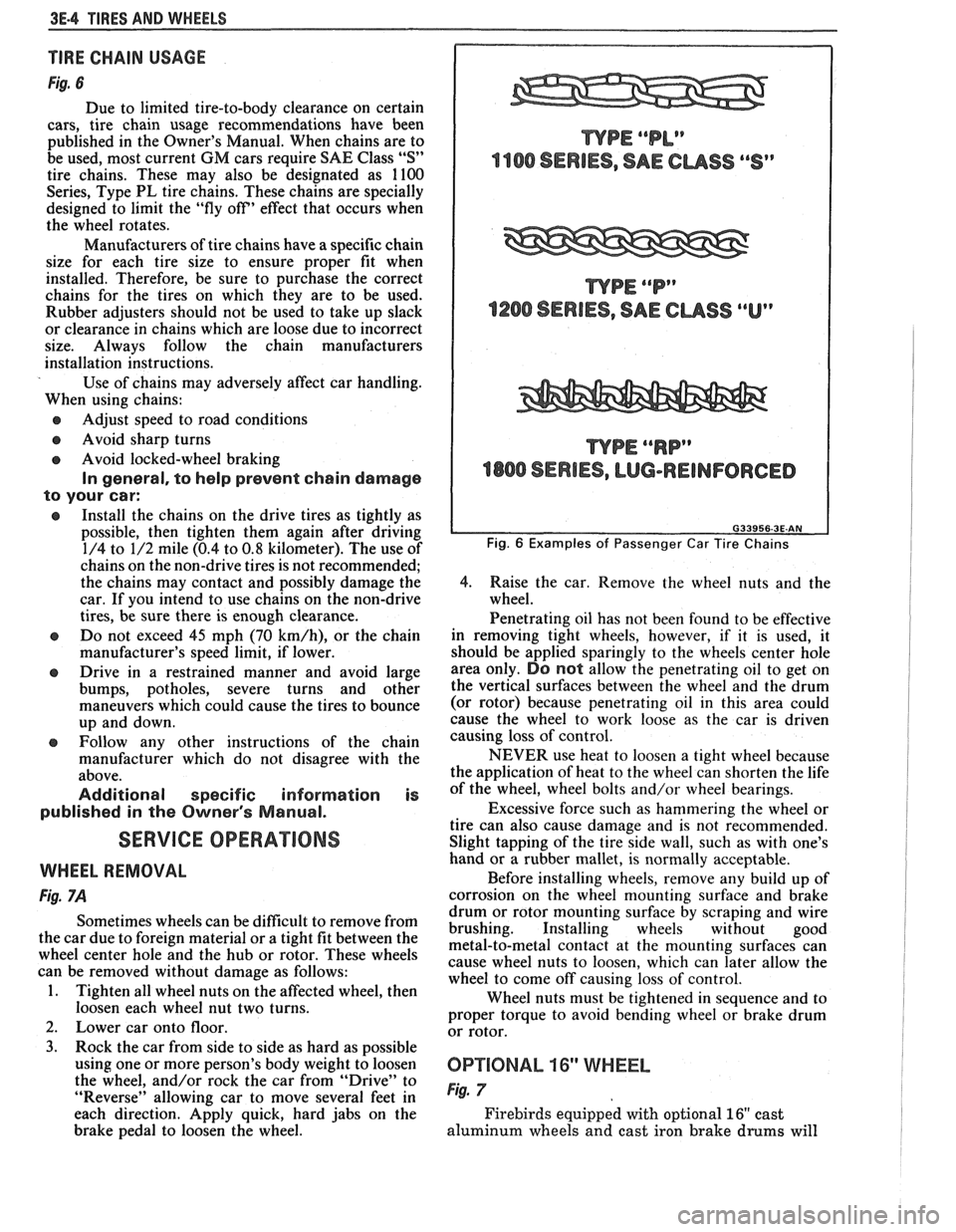
Fig. 6
Due to limited tire-to-body clearance on certain
cars, tire chain usage recommendations have been
published in the Owner's Manual. When chains are to
be used, most current
GM cars require SAE Class "S"
tire chains. These may also be designated as 1100
Series, Type PL tire chains. These chains are specially
designed to limit the "fly off' effect that occurs when
the wheel rotates.
Manufacturers of tire chains have a specific chain
size for each tire size to ensure proper fit when
installed. Therefore, be sure to purchase the correct
chains for the tires on which they are to be used.
Rubber adjusters should not be used to take up slack
or clearance in chains which are loose due to incorrect
size. Always follow the chain manufacturers
installation instructions.
Use of chains may adversely affect car handling.
When using chains:
@ Adjust speed to road conditions
@ Avoid sharp turns
@ Avoid locked-wheel braking
In general, to help prevent chain damage
to your car:
@ Install the chains on the drive tires as tightly as
possible, then tighten them again after driving
1/4 to 1/2 mile (0.4 to
0.8 kilometer). The use of
chains on the non-drive tires is not recommended;
the chains may contact and possibly damage the
car. If you intend to use chains on the non-drive
tires, be sure there is enough clearance.
e Do not exceed 45 mph (70 km/h), or the chain
manufacturer's speed limit, if lower.
@ Drive in a restrained manner and avoid large
bumps, potholes, severe turns and other
maneuvers which could cause the tires to bounce
up and down.
e Follow any other instructions of the chain
manufacturer which do not disagree with the
above.
Additional specific information is
published in the Owner's Manual.
SERVICE OPERATIONS
WHEEL REMOVAL
Fig. 7A
Sometimes wheels can be difficult to remove from
the car due to foreign material or a tight fit between the
wheel center hole and the hub or rotor. These wheels
can be removed without damage as follows:
1. Tighten all wheel nuts on the affected wheel, then
loosen each wheel nut two turns.
2. Lower car onto floor.
3. Rock the car from side to side as hard as possible
using one or more person's body weight to loosen
the wheel, and/or rock the car from
"Drive" to
"Reverse" allowing car to move several feet in
each direction. Apply quick, hard jabs on the
brake pedal to loosen the wheel.
WPE ""P"
1200 SERIES, SAE CUSS ""Up
WPE ""RP"
4800 SERIES, LUG-REINFORCED
Fig. 6 Examples of Passenger Car Tire Chains
4.
Raise the car. Remove the wheel nuts and the
wheel.
Penetrating oil has not been found to be effective
in removing tight wheels, however,
if it is used, it
should be applied sparingly to the wheels center hole
area only.
DO not allow the penetrating oil to get on
the vertical surfaces between the wheel and the drum
(or rotor) because penetrating oil in this area could
cause the wheel to work loose as the car is driven
causing loss of control.
NEVER use heat to loosen a tight wheel because
the application of heat to the wheel can shorten the life
of the wheel, wheel bolts and/or wheel bearings.
Excessive force such as hammering the wheel or
tire can also cause damage and is not recommended.
Slight tapping of the tire side wall, such as with one's
hand or a rubber mallet, is normally acceptable.
Before installing wheels, remove any build up of
corrosion on the wheel mounting surface and brake
drum or rotor mounting surface by scraping and wire
brushing. Installing wheels without good
metal-to-metal contact at the mounting surfaces can
cause wheel nuts to loosen, which can later allow the
wheel to come off causing loss of control.
Wheel nuts must be tightened in sequence and to
proper torque to avoid bending wheel or brake drum
or rotor.
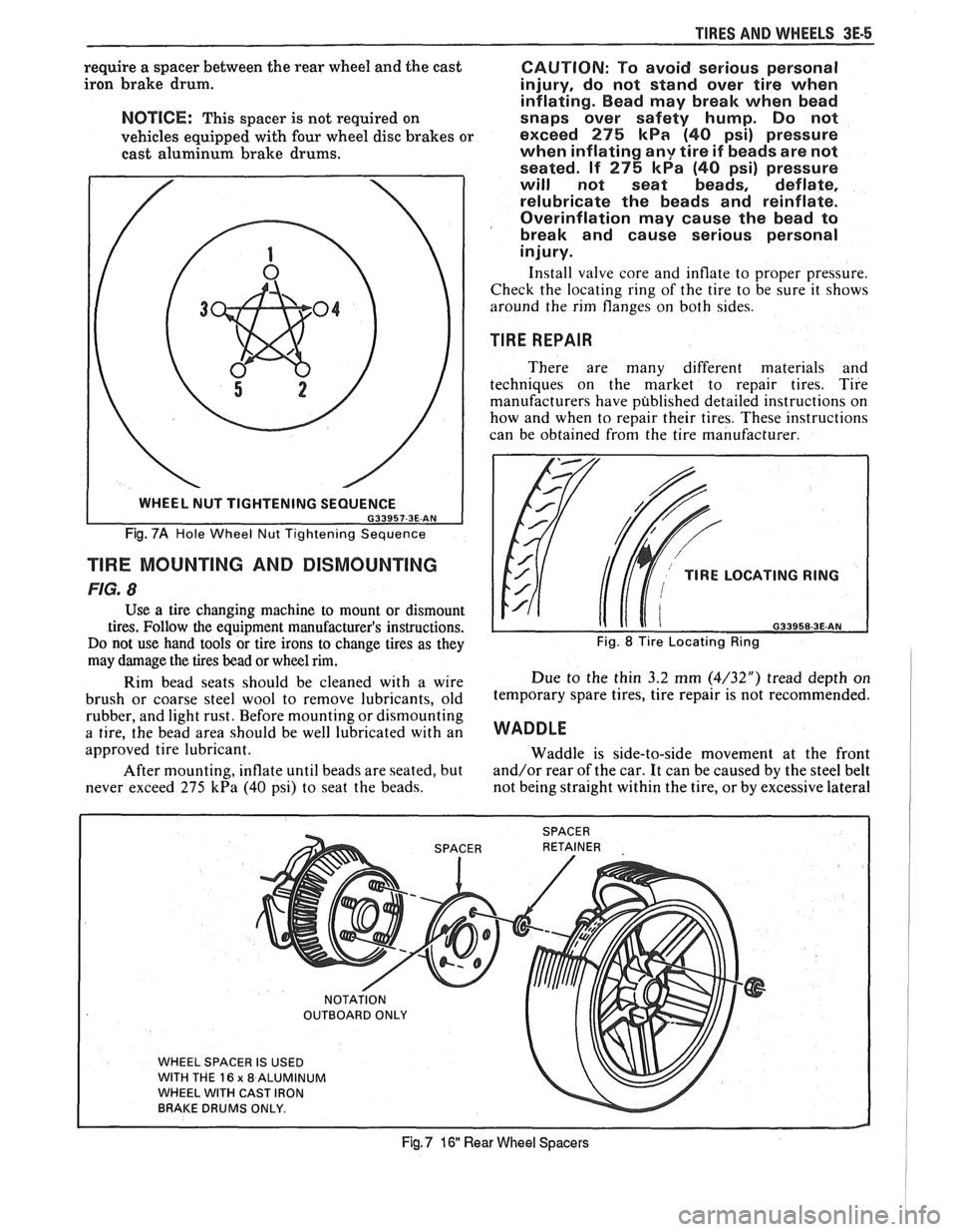
0P"FIONAL 16" WHEEL
Fig. 7
Firebirds equipped with optional 16" cast
aluminum wheels and cast iron brake
drums will
Page 236 of 1825
TIRES AND WI4EELS 3E-5
require a spacer between the rear wheel and the cast
iron brake drum.
NOTICE: This spacer is not required on
vehicles equipped with four wheel disc brakes or
cast aluminum brake drums.
Fig. 7A Hole Wheel Nut Tightening Sequence
TlRE MOUNTING AND DISMOUNTING
FIG. 8
Use a tire changing machine to mount or dismount
tires. Follow the equipment manufacturer's instructions.
Do not use hand tools or tire irons to change tires as they
may damage the tires bead or wheel rim.
Rim bead seats should be cleaned with a wire
brush or coarse steel wool to remove lubricants, old
rubber, and light rust. Before mounting or dismounting
a tire, the bead area should be well lubricated with an
approved tire lubricant.
After mounting, inflate until beads are seated, but
never exceed 275
kPa (40 psi) to seat the beads.
CAUTION: To avoid serious personal
injury, do not stand over tire when
inflating. Bead may break when bead
snaps over safety hump. Do not
exceed
275 kPa (40 psi) pressure
when inflating
any tire if beads are not
seated. If
275 kPa (40 psi) pressure
will not seat beads, deflate,
relubricate the beads and reinflate.
Overinflation may cause the bead to
break and cause serious personal
injury.
Install valve core and inflate to proper pressure.
Check the locating ring of the tire to be sure it shows
around the rim flanges on both sides.
TIRE REPAIR
There are many different materials and
techniques on the market to repair tires. Tire
manufacturers have published detailed instructions on
how and when to repair their tires. These instructions
can be obtained from the tire manufacturer.
TlRE LOCATING RING
naaaca a= AM
Fig. 8 Tire Locating Ring
Due to the thin 3.2 mm (4/32") tread depth on
temporary spare tires, tire repair is not recommended.
WADDLE
Waddle is side-to-side movement at the front
and/or rear of the car. It can be caused by the steel belt
not being straight within the tire, or by excessive lateral
WHEEL SPACER IS USED
WITH THE
16 x 8 ALUMINUM
WHEEL WITH CAST IRON
BRAKE DRUMS ONLY.
Fig, 7 16 Rear Wheel Spacers
Page 237 of 1825
3E-6 TIRES AND WHEELS
runout of the tire or wheel. Use a dial indicator on the
tire's sidewall and on the rim's flange to determine if
there is excessive lateral
runout.
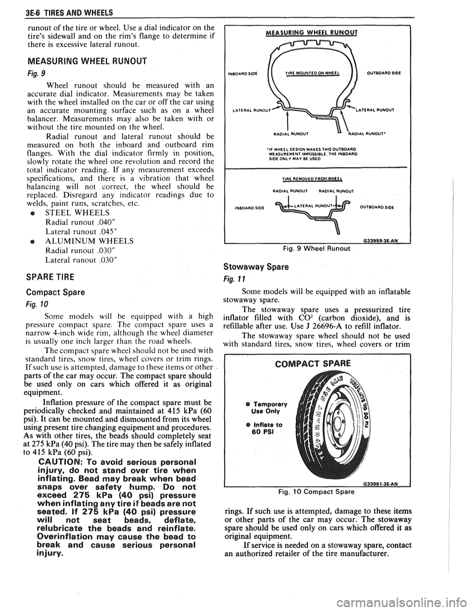
MEASURING WHEEL RUNOUT
Fig. 9
Wheel runout should be measured with an
accurate dial indicator. Measurements may be taken
with the wheel installed on the car or off the car using
an accurate mounting surface such as on a wheel
balancer. Measurements may also be taken with or
without the tire mounted on the wheel.
Radial
runout and lateral runout should be
measured on both the inboard and outboard rim
flanges. With the dial indicator firmly in position,
slowly rotate the wheel one revolution and record the
total indicator reading. If any measurement exceeds
specifications, and there is a vibration that wheel
balancing will not correct, the wheel should be
replaced. Disregard
any indicator readings due to
welds, paint runs, scratches, etc.
e STEEL WHEELS
Radial
runout .040"
Lateral runout .045"
e ALUMINUM WHEELS
Radial
runout .030"
Lateral runout .030"
SPARE TIRE
Compact Spare
Fig. 10
Some models will be equipped with a high
pressure compact spare. The compact spare uses a
narrow 4-inch wide rim, although the wheel diameter
is usually one inch larger than the road wheels.
The compact spare wheel should not be used with
standard tires, snow tires, wheel covers or trim rings.
If such use is attempted, damage to these items or other
parts of the car may occur. The compact spare should
be used only on cars which offered it as original
equipment.
Inflation pressure of the compact spare must be
periodically checked and maintained at
415 kPa (60
psi). It can be mounted and dismounted from its wheel
using present tire changing equipment and procedures.
As with other tires, the beads should completely seat
at
275 kPa (40 psi). The tire may then be safely inflated
to
415 kPa (60 psi).
CAUTION: To avoid serious personal
injury, do not stand over tire when
inflating. Bead may break when bead
snaps over safety hump. Do not
exceed
275 kPa (40 psi) pressure
when inflating any tire
if beads are not
seated. If
275 kPa (40 psi) pressure
will not seat beads, deflate,
relubricate the beads and reinflate.
Overinflation may cause the bead to
break and cause serious personal
injury.
INBOARD SIDE TIRE MOUNTED ON fVHEEL OUTBOARD SIDE
RADIAL
RUNOUT'
'IF WHEEL DESIGN MAKES THISOUTBOARD MEASUREMENT IMPOSSIBLE. THE INBOARD
SIDE ONLY MAY BE USED
I RADIAL RUNOUT RADIAL RUNDUT I
INBOARD SIDE OUTBOARD SIDE
Fig. 9 Wheel Runout
Stowaway Spare
Fig. 11
Some models will be equipped with an inflatable
stowaway spare.
The stowaway spare uses a pressurized tire
inflator filled with
C02 (carbon dioxide), and is
refillable after use. Use
J 26696-A to refill inflator.
The stowaway spare wheel should not be used
with standard tires, snow tires, wheel covers or trim
@ Temporary
Use Only
@ Inflate to 80 PSI
Fig. 10 Compact Spare
rings. If such use is attempted, damage to these items
or other parts of the car may occur. The stowaway
spare should be used only on cars which offered
it as
original equipment.
If service is needed on a stowaway spare, contact
an authorized retailer of the tire manufacturer.
Page 238 of 1825
TIRES AND WHEELS 3E-7
STMAWAY SPARE
TEMPORARY USE ONLV
Fig. 11 Stowaway Spare
MATCH MOUNTING
Fig. 12
Tires and wheels are "match-mounted" at the
assembly plant. This means that the radially stiffest
part of the tire, or "high spot", is matched to the
smallest radius or "low spot" of the wheel.
The "high spot" of the tire is originally marked
by a yellow paint mark
or adhesive label on the
outboard sidewall.
The "low spot" of the wheel will be at the location
of the valve stem.
Before dismounting
a tire from its wheel, a line
should be scribed on the tire at the valve
stem to assure
that it is remounted
ill the same poqition.
Replacement tireq and wheels that are of original
equipment quality will have their "high and low spot"
marked in the same manner.
DOT OR LABEL
SPOT I WHEEL TRAMP I
ADD BALANCE WEIGHTS HERE I
I CORRECTIVE WEIGtiYS I
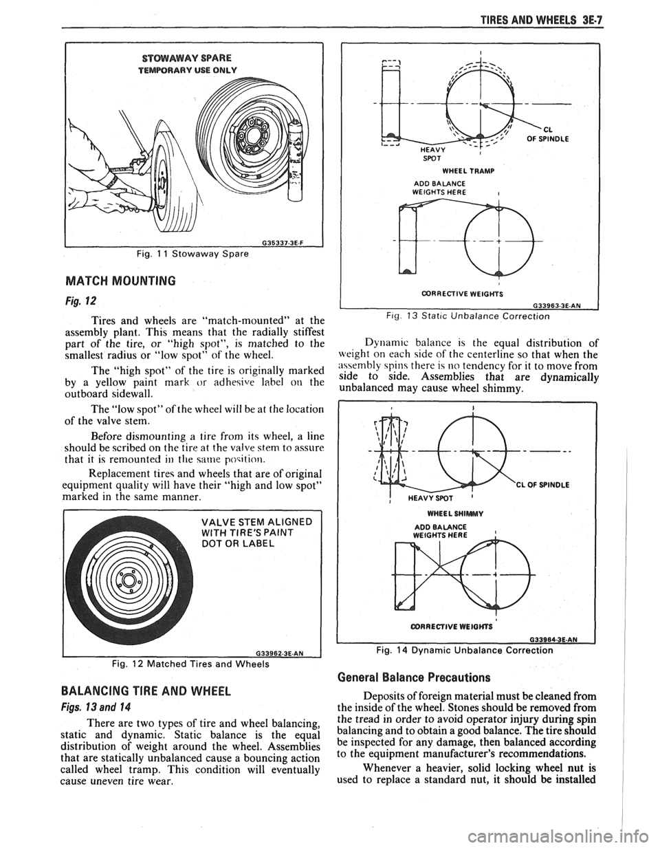
L G33963-3E.AN Fig 13 Stat~c Unbalance Correction
Dynam~c balance 1s the equal distribution of
weight on each side of the centerline so that when the
n\\embly spin there 14 no tendency for it to move from
side to side. Assemblies that are dynamically
unbalanced may cause wheel shimmy.
WHEEL SHlWWUV
ADDBALANCE , WEtGHTS HERE
Fig. 14 Dynamic Unbalance Correction
Fig.
12 Matched Tires and Wheels
General Balance Precautions
BALANCING TIRE AND WHEEL
Figs, 13 and 14
There are two types of tire and wheel balancing,
static and dynamic. Static balance is the equal
distribution of weight around the wheel. Assemblies
that are statically unbalanced cause a bouncing action
called wheel tramp. This condition will eventually
cause uneven tire wear. Deposits
of foreign material must be cleaned from
the inside of the wheel. Stones should be removed from
the tread in order to avoid operator injury during spin
balancing and to obtain a good balance. The tire should
be inspected for any damage, then balanced according
to the equipment manufacturer's recommendations.
Whenever a heavier, solid locking wheel nut is
used to replace a standard nut, it should
be installed
Page 239 of 1825
3E-8 TIRES AND WHEELS
nearest the valve stem, and a 1/2 ounce balance weight
should be added 180" opposite the locking nut on the
wheel's inboard side.
When rotating tires, always re-install the locking
nut nearest the tire valve stem so that it remains
opposite the 1/2 ounce balance weight. This procedure
will improve the on-car wheel balance by compensating
for the heavy locking wheel nut.
Off-Car Balancing
Most electronic off-car balancers are more
accurate than the on-car spin balancers. They are easy
to use and give a dynamic (two plane) balance.
Although they do not correct for drum or rotor
unbalance as does on-car spin balancing, this is
overcome by their accuracy (usually to within 1/8
ounce). When balancing off-car, the wheel should
locate on the balancer with a cone through the back
side of the center pilot hole (not by the wheel stud
holes).
On-Car Balancing
When needed, on-car balancing will help correct
vibrations due to brake drum, rotor, and wheel cover
imbalance.
When balancing on car, do not remove the
balance weights from the off-car dynamic balance. If
more than one ounce of additional weight is required,
it should be split between the inner and outer rim
flange.
NOTICE: The driven tire and wheel assemblies
should be spun using the engine. Limit speed as
stated in the following Caution.
CAUTION: Do not spin the drive
wheels faster than
35 mph (55 km/h)
as indicated by the speedometer. This
limit is necessary because the
speedometer indicates only one-half
of the actual wheel speed when one
drive wheel is spinning and the other
drive wheel is stopped. Personal injury
and damage may result from high
speed spinning.
CAUTION: On cars equipped with
limited slip rear axles, do not attempt
to balance a tire on a
drive wheel with
the other drive wheel on the ground.
The car may drive through this wheel
and cause the car to move
unexpectedly, resulting in personal
injury and property damage.
To distinguish between standard rear axle and
limited slip, raise rear of car so both tires are clear of
ground. With the transmission in park (in gear with
manual transmission), attempt to turn one wheel by
hand. If the wheel can be turned, it is a standard rear
axle; if the wheel cannot be turned, it is a limited slip
rear axle. Also, check for Limited Slip
(G80) on Service
Parts Identification label.
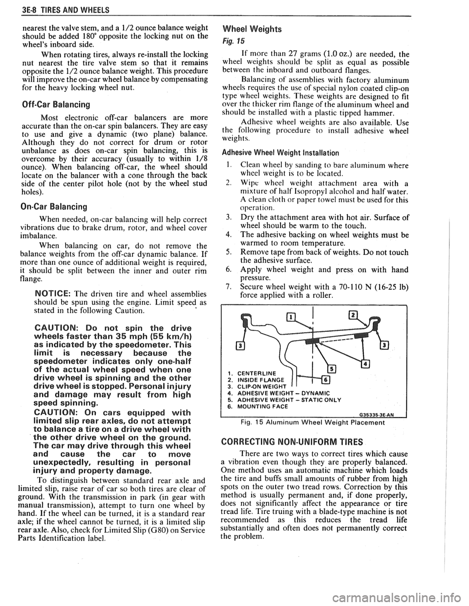
Wheel Weights
Fig. 15
If more than 27 grams (1.0 oz.) are needed, the
wheel weights should be split as equal as possible
between the inboard and outboard flanges.
Balancing of' assemblies with factory aluminum
wheels requires the use of special nylon coated clip-on
type wheel weights. These weights are designed to fit
over the thicker rim flange of the aluminum wheel and
should be installed with a plastic tipped hammer.
Adhesive wheel weights are also available. Use
the following procedure to install adhesive wheel
weights.
Adhesive Wheel Weight Installation
1. Clean wheel by sanding to bare aluminum where
wheel weight is to be located.
2. Wipe wheel weight attachment area with a
mixture of half Isopropyl alcohol and half water.
A clean cloth or paper towel niust be used for this
operat ion.
3. Dry the attachment area with hot air. Surface of
wheel should be warm to the touch.
4. The adhesive backing on wheel weights must be
warmed to room temperature.
5. Remove tape from back of weights. Do not touch
the adhesive surface.
6. Apply wheel weight and press on with hand
pressure.
7. Secure wheel weight with a 70-1 10
N (16-25 lb)
force applied with a roller.
CENTERLINE
1 INSIDE FLANGE CLIPBN WEIGHT 4. ADHESIVE WEIGHT - DYNAMIC 5. ADHESIVE WEIGHT -STATIC ONLY 6. MOUNTING FACE
Fig. 15 Aluminum Wheel Weight Placement
CORRECTING NON-UNIFORM TIRES
There are two ways to correct tires which cause
a vibration even though they are properly balanced.
One method uses an automatic machine which loads
the tire and buffs small amounts of rubber from high
spots on the outer two tread rows. Correction by this
method is usually permanent and, if done properly,
does not significantly affect the appearance or tire
tread life. Tire truing with a blade-type
machine is not
recommended as this reduces the tread life
substantially and often does not permanently correct
the problem.
Page 240 of 1825
TIRES AND WHEELS 3E-9
Another method is to dismount the tire and
rotate it 180 degrees on the rim. It is important that
this be done on tire and wheel assemblies which are
known to be causing a vibration as it is just as likely to
cause good assemblies to vibrate.
Refer to Section 3, "Vibration Diagnosis" for
more details.
ALUMINUM WHEEL CLEANING
Aluminum wheels should be cleaned and waxed
regularly. Do not use abrasive cleaners, as they could
damage the protective coating.
ALUMINUM WHEEL HUB CAP
Remove or Disconnect
1. Tire and wheel assembly
2. Place a block of wood approximately 2" in
diameter with a squared off end against the back
surface of the cap.
A sharp hammer biow on the
block of wood will
remove the cap.
Install or Connect
1. Place
cap into position at wheel opening and
place a block of wood at least three inches in
diameter against cap face. Install cap by striking
block of wood with hammer.
2. Tire and wheel assembly
NOTICE: Failure to hit cap squarely without the
load distributed evenly could result in permanent
damage to the cap.
ALUMINUM WHEEL POROSITY REPAIR
1. Remove tire and wheel assembly.
2. Locate
leaking areas by inflating tire to 345
kPa
(50 psi) and dipping tire and wheel assembly into
a water bath.
3. Mark
leak areas and remove tire from wheel.
4. Scuff inside surface at leak area with 80 grit
sandpaper and clean area with general purpose
cleaner such as
3M #08984 or equivalent.
5. Apply 1/8" thick layer of adhesive/sealant P/N
1052366 or equivalent to leak area and allow
twelve hours of drying time.
6. Mount tire on wheel, pressurize to 345 kPa (50
psi) and check for leaks.
CAUTION: To avoid serious personal
injury, do not stand over tire when
inflating. Bead may break when bead
snaps over safety hump. Do not
exceed
275 kPa (40 psi) pressure
when inflating any tire if beads are
not seated.
14 275 kPa (40 psi)
pressure will not seat beads, deflate,
relubricate the beads and reinflate.
Overinflation may cause the bead to
break and cause serious personal
injury.
7. Adjust
tire pressure to meet specifications.
8. Balance tire and wheel assembly.
9. Install tire and wheel assembly.
ALUMINUM WHEEL REFINISHING
A protective clear or color coating is applied to
the surface of original equipment cast aluminum
wheels.
A surface degradation condition can begin to
develop if frequent, repeated automatic car wash
cleaning abrades or wears off the factory applied
protective coating. This can happen at some automatic
car wash facilities using aggressive silicon carbide
tipped tire brushes
to clean white walls and tires. Once
the protective coating is
damaged, exposure to caustic
cleaners and/or road salt further causes surface
degradation. The following procedure details how to
strip, clean
and recoat aluminum wheels that are
affected by these conditions.
Required Materials:
A~nchern Alumi Prep #33 - stock
#DX533 or equivalent - cleaning and
conditioning chemical for aluminum.
Amchem Alodine
# 1001 - stock #DXSOT
or equivalent - coating chemical for
aluminum.
Ditzler Delclear Acrylic Urethane Clear
-
stock #DAU-75 or equivalent.
Ditzler Delthane Ultra-Urethane Additive
- stock DXR-80 or equivalent.
Service Procedure:
1. Mark wheel and wheel stud for position on car.
2. Remove tire and wheel assembly from car.
3. Mark location of outboard weights and remove.
4. Wash wheel inside and out with water base all
purpose cleaner. Remove grease and oil with
solvent cleaner.
5. Mask off tire prior to painting.
6. Select and follow the correct procedure,
"Aluminum Damage on Wheel Surface" or
"Clear Coat Damage on Unpainted Wheels".
7. Replace wheel weights with nylon coated
weights.
8. Install tire and wheel assembly on car and tighten
wheel nuts to proper torque.
Accent Color Preparation
1. Sand over painted areas that will not require
recoloring with 400 grit (wet or dry) to promote
adhesion of clear coat.
Aluminum Damage on Wheel Surface
1. Mount tire and wheel on brake lathe and spin
slowly.
2. Sand wheel with backing block or pad by holding
abrasive flat to surface of wheel and moving
slowly back and forth from center to outer edge
to remove damage. Use the following sandpaper
grits in the order listed.
A. Sand with 80 grit
B. Sand with 150 grit
C. Sand with 240 grit
3. Continue with "Recoating Procedure."