RENAULT KANGOO 1997 KC / 1.G Foult Finding - Injection Workshop Manual
Manufacturer: RENAULT, Model Year: 1997, Model line: KANGOO, Model: RENAULT KANGOO 1997 KC / 1.GPages: 363
Page 341 of 363
1EC761.0
AIRBAG - SEAT BELT PRETENSIONERS
Fault finding -Wiring
Fault finding - XRBAG fiche
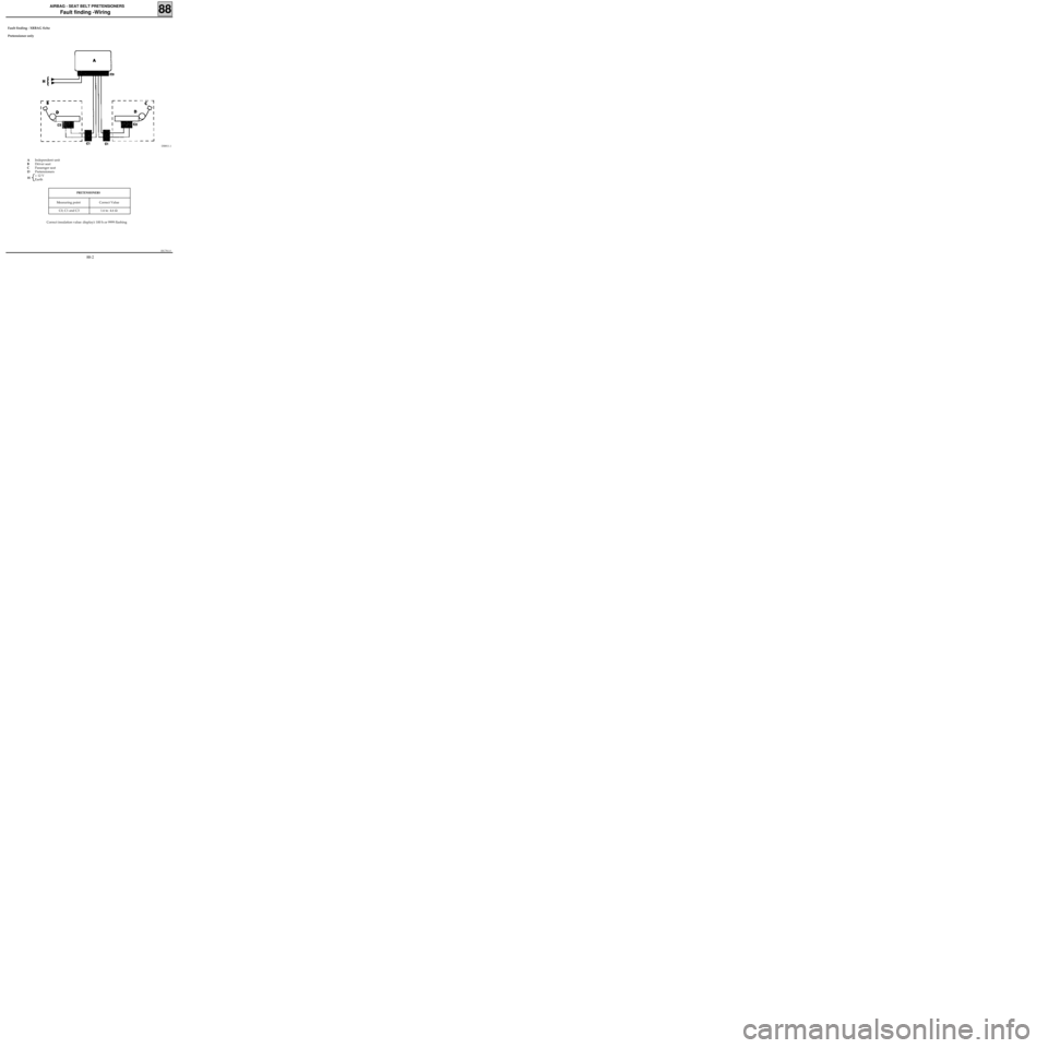
Pretensioner only
88
DI8811.1
Correct insulation value: display≥ 100 h or 9999 flashing
PRETENSIONERS
Measuring point Correct Value
C0, C1 and C3 1.6 to 4.6 Ω
AIndependent unit
BDriver seat
CPassenger seat
DPretensioners
+ 12 V
Earth
H
88-2
Page 342 of 363
1EC761.0
AIRBAG - SEAT BELT PRETENSIONERS
Fault finding -Wiring
Fault finding - XRBAG Fiche
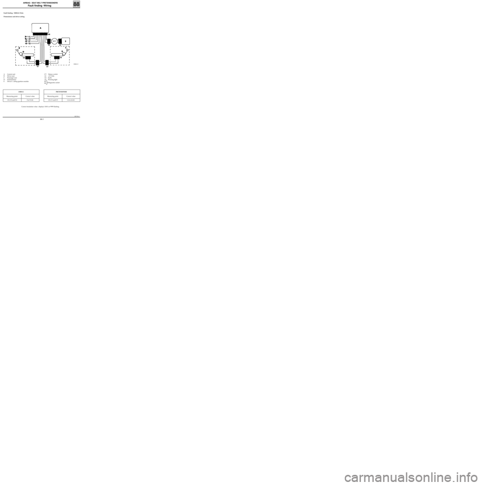
Pretensioner and driver airbag
88
DI8812.3
Correct insulation value : display≥ 100 h or 9999 flashing
PRETENSIONERS
Measuring point Correct value
C0, C1 and C3 1.6 to 4.6 Ω
AIRBAG
Measuring point Correct value
C0, C2 and C4 2 to 9.4 Ω
CT Rotary switch
A1 +12 Volts
A3 Earth
A2 Warning light
B1
B2Diagnostic socket A Central unit
B Driver seat
C Passenger seat
D Pretensioners
E Driver’s airbag ignition module
88-3
Page 343 of 363

1EC761.0
AIRBAG - SEAT BELT PRETENSIONERS
Fault finding -Wiring
Fault finding - XRBAG Fiche
Pretensioner , driver’s airbag and passenger’s airbag
88
DI8813.2
PRETENSIONERS
Measuring point Correct value
C0, C1 and C3 1.6 to 4.6 Ω
AIRBAG
Measuring point Correct value
Driver C0, C2 and C4 2 to 9.4 Ω
Passenger C0 and C4 1.6 to 4.6 Ω
CT Rotary switch
A1 +12 Volts
A3 Earth
A2 Warning light
B1
B2Diagnostic socket A Central unit
B Driver’s seat
C Passenger’s seat
D Pretensioners
E Driver’s airbag ignition module
G Passenger’s airbag ignition module
Correct insulation value : display≥ 100 h or 9999 flashing
88-4
Page 344 of 363

1EC761.0
AIRBAG - SEAT BELT PRETENSIONERS
Fault finding - XR25 Fiche
PRESENTATION OF XR25 FICHE N° 49
88
FI21749
88-5
Page 345 of 363
1EC761.0
AIRBAG - SEAT BELT PRETENSIONERS
Fault finding - XR25 fiche
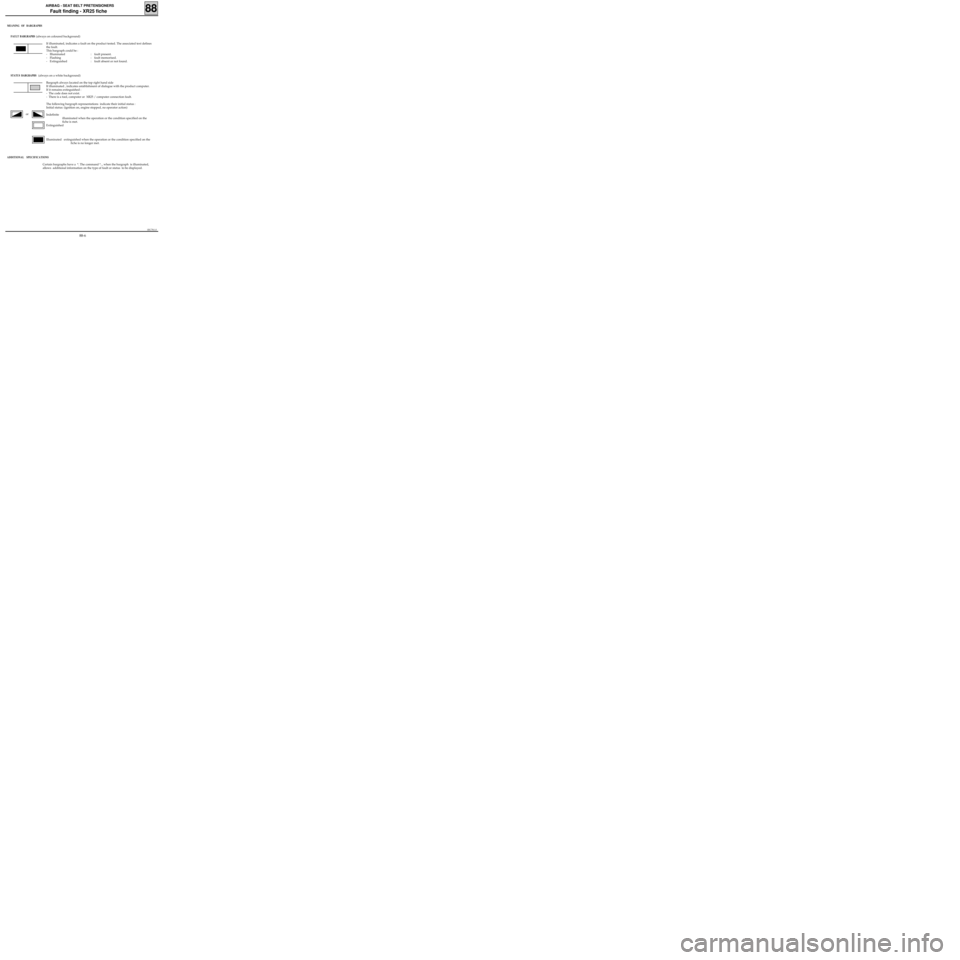
MEANING OF BARGRAPHS
FAULT BARGRAPHS
(always on coloured background)
If illuminated, indicates a fault on the product tested. The associated text defines
the fault.
This bargraph could be :
- Illuminated : fault present.
- Flashing : fault memorised.
- Extinguished : fault absent or not found.
STATUS BARGRAPHS (always on a white background)
Bargraph always located on the top right hand side
If illuminated , indicates establishment of dialogue with the product computer.
If it remains extinguished :
- The code does not exist.
- There is a tool, computer or XR25 / computer connection fault.
The following bargraph representations indicate their initial status :
Initial status: (ignition on, engine stopped, no operator action)
Indefinite
illuminated when the operation or the condition specified on the
fiche is met.
Extinguished
Illuminated extinguished when the operation or the condition specified on the
fiche is no longer met.
ADDITIONAL SPECIFICATIONS
Certain bargraphs have a *. The command *.., when the bargraph is illuminated,
allows additional information on the type of fault or status to be displayed.
or
88
88-6
Page 346 of 363

1EC761.0
AIRBAG - SEAT BELT PRETENSIONERS
Fault finding - Interpretation of XR25 bargraphs
Bargraph 1 right hand side extinguished Fiche n° 49
Code present1
The computers which only control the operation of the seat belt pretensioners do
not have XR25 fault finding (check to be carried out with XRBAG).
When communication is established, deal with any illuminated fault bargraphs.AFTER REPAIR NOTES
Check the presence and condition of the airbag fuse .
Check the condition of the computer connector and the condition of the connections.
Check that the computer is correctly fed :
- Disconnect the airbag computer and fit the 30 track adaptor of the XRBAG.
- Check and ensure the presence + after ignition feed between the terminals marked
Earth and +after ignition feed.
Check that the diagnostic socket is correctly fed :
-+ Before ignition feed on track 16.
-Earth on track 5.
Check the continuity and insulation of the lines of the diagnostic socket / airbag computer connection:
- Between the terminal marked L and track 15 of the diagnostic socket .
- Between the terminal marked K and track 7 of the diagnostic socket .
If dialogue is still not established after these various checks, replace the airbag computer (consult the
section on "Aid" for this operation).
Ensure that the XR25 is not the cause of the fault by trying to communicate with the computer on
another vehicle .
Check that the ISO selector is in position S8, that the latest XR25 cassette and the correct access code are
being used.
Check the battery voltage and carry out the operations necessary to obtain the correct voltage (10.5 volts
< U battery< 16 volts).
88
88-7
Page 347 of 363

1EC761.0
AIRBAG - SEAT BELT PRETENSIONERS
Fault finding - Interpretation of XR25 bargraphs
Bargraph 1 left hand side illuminated or flashing Fiche n° 49
Computer 1
None
NoneAFTER REPAIR NOTES
Replace the airbag computer (consult the section "Aid" for this operation).
88
88-8
Page 348 of 363
1EC761.0
AIRBAG - SEAT BELT PRETENSIONERS
Fault finding - Interpretation of XR25 bargraphs
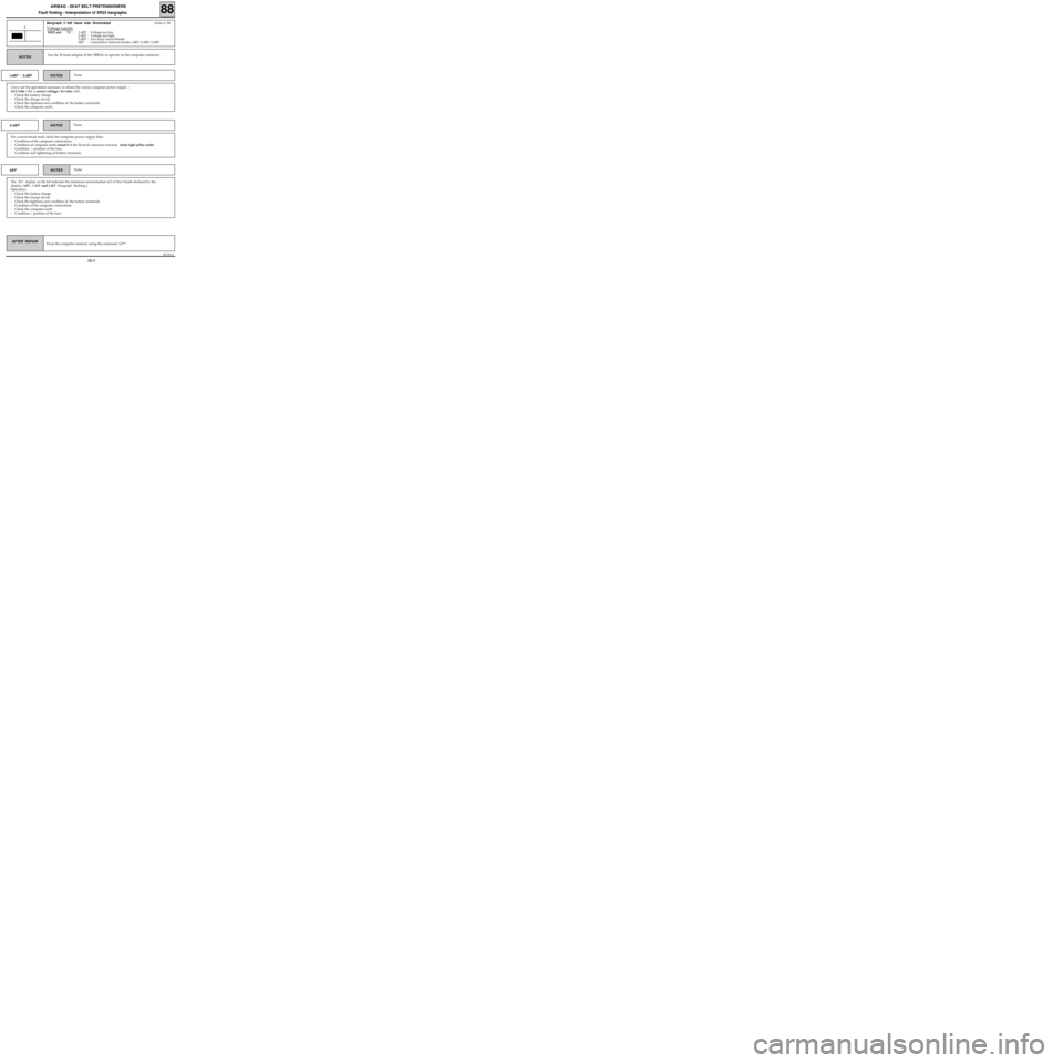
Bargraph 2 left hand side illuminated Fiche n° 49
Voltage supply
XR25 aid:*02 : 1.dEF : Voltage too low
2.dEF : Voltage too high
3.dEF : Too many micro-breaks
dEF : Cumulative between faults 1.dEF/2.dEF/3.dEF
2
Use the 30 track adaptor of the XRBAG to operate on the computer connector .
Erase the computer memory using the command G0**. AFTER REPAIR NOTES
Carry out the operations necessary to obtain the correct computer power supply :
10.5 volts ± 0.1 < correct voltage< 16 volts ± 0.1.
- Check the battery charge.
- Check the charge circuit.
- Check the tightness and condition of the battery terminals.
- Check the computer earth .
NoneNOTES I.dEF - 2.dEF
For a micro-break fault, check the computer power supply lines :
- Condition of the computer connections.
- Condition of computer earth (track 9 of the 30 track connector towards front right pillar earth).
- Condition / position of the fuse.
- Condition and tightening of battery terminals.
NoneNOTES 3.dEF
The dEF display on the kit indicates the minimum memorisation of 2 of the 3 faults declared by the
display
1.dEF, 2.dEF and 3.dEF (bargraph flashing ).
Operation:
- Check the battery charge.
- Check the charge circuit.
- Check the tightness and condition of the battery terminals.
- Condition of the computer connections.
- Check the computer earth .
- Condition / position of the fuse.
NoneNOTES dEF
88
88-9
Page 349 of 363

1EC761.0
AIRBAG - SEAT BELT PRETENSIONERS
Fault finding - Interpretation of XR25 bargraphs
Bargraph 5 left hand side illuminated Fiche n° 49
Resistance on the driver’s airbag line
XR25 aid :*05 : CC : Short-circuit
CO : Open circuit
5
Never carry out measurements on the trigger lines with equipment other than the
XRBAG.NOTES
Lock the computer with the command G80* on the XR25.
Switch off the ignition and remove the two mounting bolts of the steering wheel cushion.
Check that it is correctly connected.
Disconnect the steering wheel cushion and connect a dummy ignition module to the ignition module
connector . Switch on the ignition and carry out an XR25 check.
Replace the airbag cushion if the fault has been memorised (fault no longer declared).
The XRBAG tool MUST be used for checking resistance at point C2 of the driver’s airbag circuit.
If the value obtained is not correct, replace the rotary switch below the steering wheel.
Reconnect the rotary switch below the steering wheel, disconnect the computer connector and fit the 30
track adaptor.
The XRBAG tool MUST be used for checking resistance on the wire marked B on the adaptor.
If the value obtained is not correct,
check the 30 track connector connection (tracks 10 and 11) and
replace the wiring if necessary.
If the checks carried out have not proven the existence of a fault, replace the airbag computer (consult
the section "Aid" for this operation).
Reconnect the driver’s airbag ignition module and remount the steering wheel cushion.
With the ignition switched off, disconnect, then reconnect the connector for the rotary switch below the
steering wheel.
Operate on the connection if bargraph 5 left hand side begins to flash .
Erase the computer memory using the command G0** then switch off the ignition.
carry out another check with the XR25 and, if there is no fault, unlock the
computer using command G81*.
Destroy the airbag cushion if it has been replaced (tool Elé. 1287).
AFTER REPAIR
88
88-10
Page 350 of 363
1EC761.0
AIRBAG - SEAT BELT PRETENSIONERS
Fault finding - Interpretation of XR25 bargraphs
Bargraph 5 right hand side illuminated Fiche n° 49
Insulation of driver’s airbag line
XR25 aid :*25 : CC.1 : Short circuit at 12 volts
CC.0 : Short circuit to earth
5
Never carry out measurements on the trigger lines with equipment other than the
XRBAG.NOTES
Lock the computer using command G80* on the XR25.
Switch off the ignition and remove the two mounting bolts of the steering wheel cushion .
Check the condition of the trigger wire.
The XRBAG tool MUST be use for measuring insulation appropriate to the type of fault at point C2 of the
driver’s airbag circuit .
If the value obtained is not correct , replace the rotary switch under the steering wheel .
Reconnect the rotary switch under the steering wheel , disconnect the computer connector and fit the 30
track adaptor.
The XRBAG tool MUST be used for measuring insulation appropriate to the type of fault on the wire
marked B on the adaptor.
If the value obtained is not correct , check the 30 track connector connection (tracks 10 and 11) and
replace the wiring if necessary.
If the checks carried out have not proven the existence of a fault, replace the airbag computer (consult
the section "Aid" for this operation).
Reconnect the driver’s airbag ignition module and remount the steering wheel cushion.
Erase the computer memory using the command G0** then switch off the ignition.
Carry out another XR25 check and if there is no fault, unlock the computer using
command G81*.
Destroy the airbag cushion if it has been replaced (tool Elé. 1287).
AFTER REPAIR
88
88-11