RENAULT KANGOO 2013 X61 / 2.G Diesel DCM 1.2 Injection Workshop Manual
Manufacturer: RENAULT, Model Year: 2013, Model line: KANGOO, Model: RENAULT KANGOO 2013 X61 / 2.GPages: 204, PDF Size: 0.99 MB
Page 141 of 204
13B-141V1 MR-376-X76-13B000$110.mif
13B
DCM 1.2 Injection
Program no.: 4C
Vdiag No.: 08
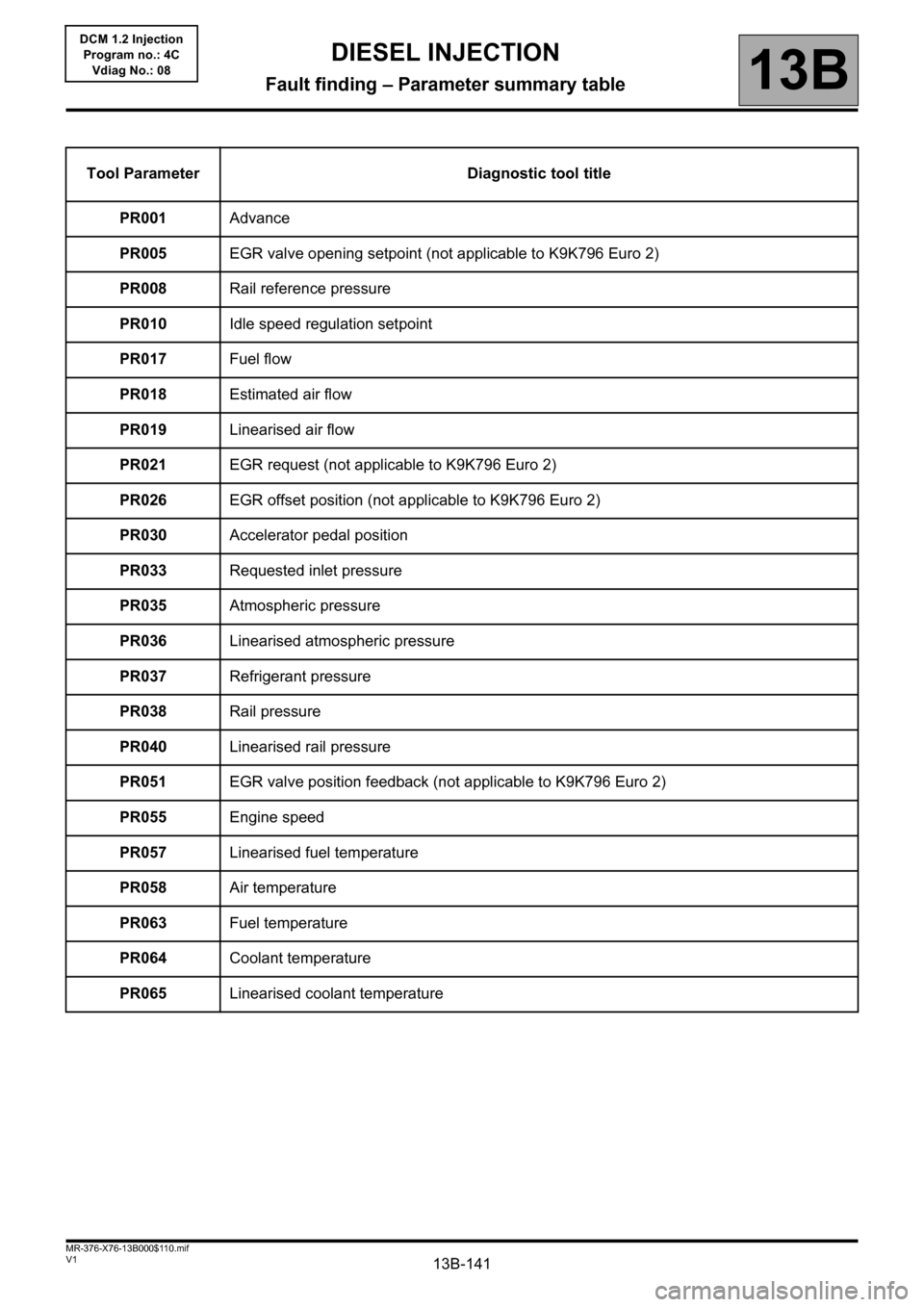
Tool Parameter Diagnostic tool title
PR001Advance
PR005EGR valve opening setpoint (not applicable to K9K796 Euro 2)
PR008Rail reference pressure
PR010Idle speed regulation setpoint
PR017Fuel flow
PR018Estimated air flow
PR019Linearised air flow
PR021EGR request (not applicable to K9K796 Euro 2)
PR026EGR offset position (not applicable to K9K796 Euro 2)
PR030Accelerator pedal position
PR033Requested inlet pressure
PR035Atmospheric pressure
PR036Linearised atmospheric pressure
PR037Refrigerant pressure
PR038Rail pressure
PR040Linearised rail pressure
PR051EGR valve position feedback (not applicable to K9K796 Euro 2)
PR055Engine speed
PR057Linearised fuel temperature
PR058Air temperature
PR063Fuel temperature
PR064Coolant temperature
PR065Linearised coolant temperature
DIESEL INJECTION
Fault finding – Parameter summary table
Page 142 of 204
13B-142V1 MR-376-X76-13B000$110.mif
DIESEL INJECTION
Fault finding – Parameter summary table13B
DCM 1.2 Injection
Program no.: 4C
Vdiag No.: 08
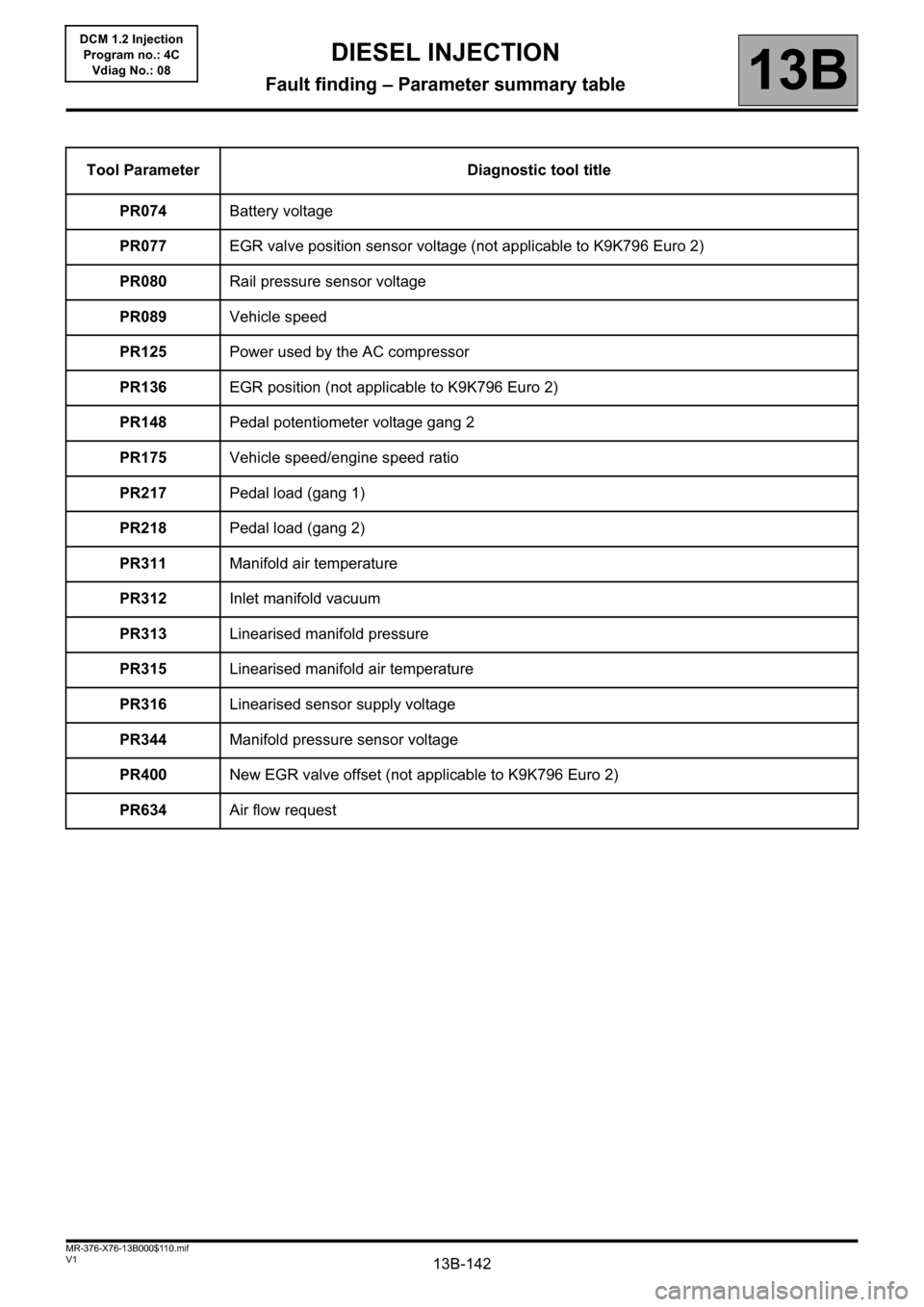
Tool Parameter Diagnostic tool title
PR074Battery voltage
PR077EGR valve position sensor voltage (not applicable to K9K796 Euro 2)
PR080Rail pressure sensor voltage
PR089Vehicle speed
PR125Power used by the AC compressor
PR136EGR position (not applicable to K9K796 Euro 2)
PR148Pedal potentiometer voltage gang 2
PR175Vehicle speed/engine speed ratio
PR217Pedal load (gang 1)
PR218Pedal load (gang 2)
PR311Manifold air temperature
PR312Inlet manifold vacuum
PR313Linearised manifold pressure
PR315Linearised manifold air temperature
PR316Linearised sensor supply voltage
PR344Manifold pressure sensor voltage
PR400New EGR valve offset (not applicable to K9K796 Euro 2)
PR634Air flow request
Page 143 of 204
13B-143
AFTER REPAIRDeal with any faults displayed by the diagnostic tool.
Clear the computer memory.
Carry out a road test followed by another check with the diagnostic tool.
V1 MR-376-X76-13B000$120.mif
13B
DCM 1.2 Injection
Program no.: 4C
Vdiag No.: 08
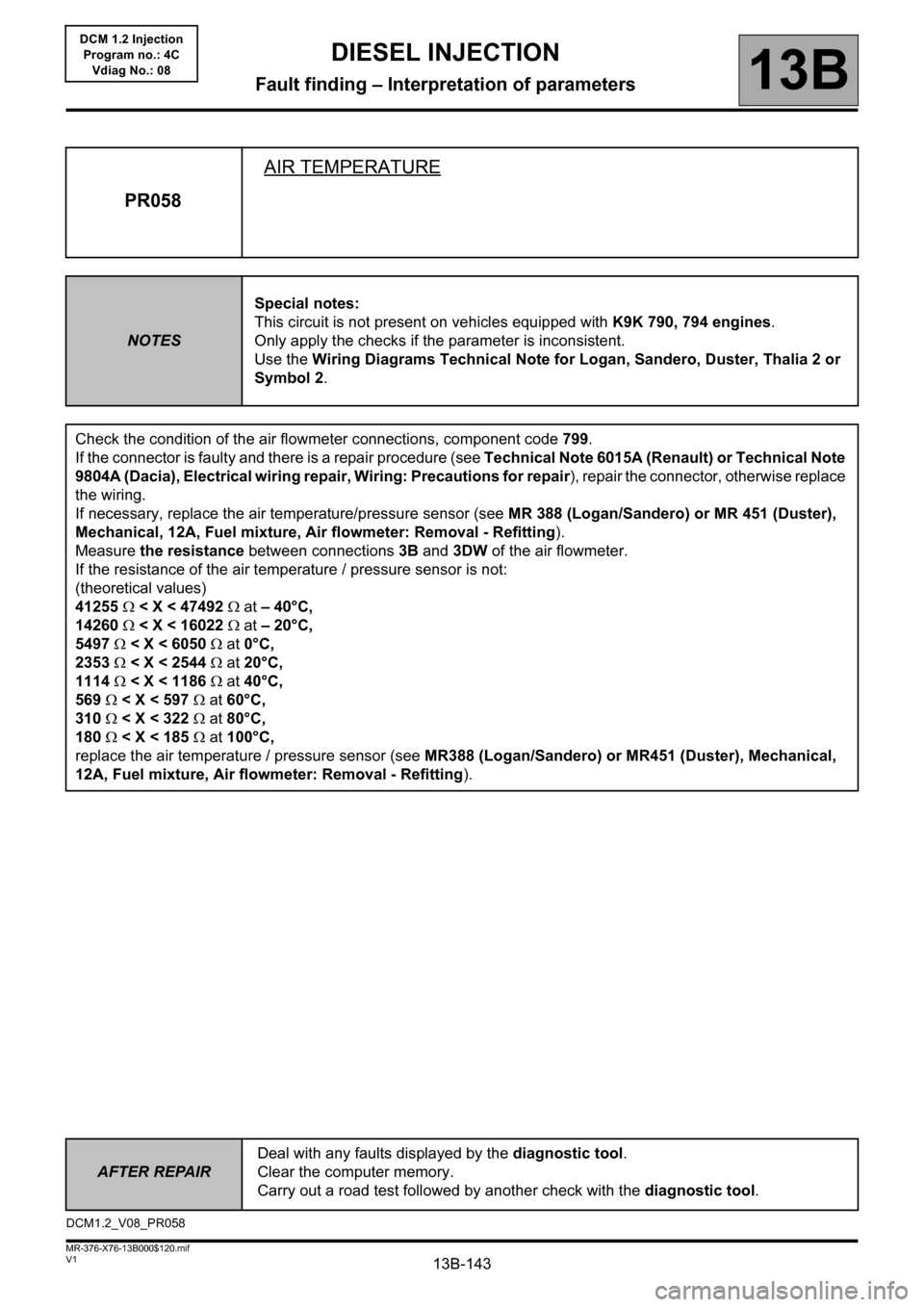
PR058AIR TEMPERATURE
NOTESSpecial notes:
This circuit is not present on vehicles equipped with K9K 790, 794 engines.
Only apply the checks if the parameter is inconsistent.
Use the Wiring Diagrams Technical Note for Logan, Sandero, Duster, Thalia 2 or
Symbol 2.
Check the condition of the air flowmeter connections, component code 799.
If the connector is faulty and there is a repair procedure (see Technical Note 6015A (Renault) or Technical Note
9804A (Dacia), Electrical wiring repair, Wiring: Precautions for repair), repair the connector, otherwise replace
the wiring.
If necessary, replace the air temperature/pressure sensor (see MR 388 (Logan/Sandero) or MR 451 (Duster),
Mechanical, 12A, Fuel mixture, Air flowmeter: Removal - Refitting).
Measure the resistance between connections 3B and 3DW of the air flowmeter.
If the resistance of the air temperature / pressure sensor is not:
(theoretical values)
41255 < X < 47492 at – 40°C,
14260 < X < 16022 at – 20°C,
5497 < X < 6050 at 0°C,
2353 < X < 2544 at 20°C,
1114 < X < 1186 at 40°C,
569 < X < 597 at 60°C,
310 < X < 322 at 80°C,
180 < X < 185 at 100°C,
replace the air temperature / pressure sensor (see MR388 (Logan/Sandero) or MR451 (Duster), Mechanical,
12A, Fuel mixture, Air flowmeter: Removal - Refitting).
DCM1.2_V08_PR058
DIESEL INJECTION
Fault finding – Interpretation of parameters
Page 144 of 204
13B-144
AFTER REPAIRDeal with any faults displayed by the diagnostic tool.
Clear the computer memory.
Carry out a road test followed by another check with the diagnostic tool.
V1 MR-376-X76-13B000$120.mif
DIESEL INJECTION
Fault finding – Interpretation of parameters13B
DCM 1.2 Injection
Program no.: 4C
Vdiag No.: 08
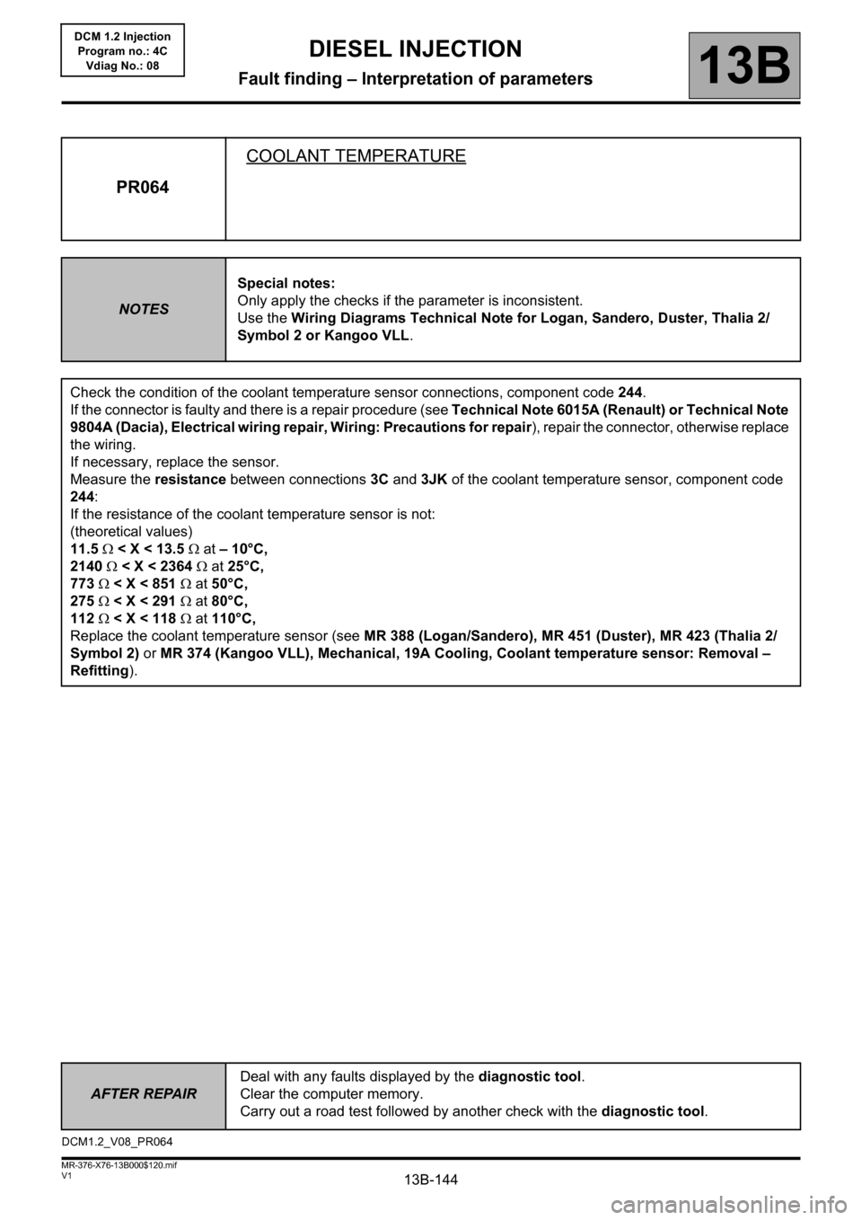
PR064COOLANT TEMPERATURE
NOTESSpecial notes:
Only apply the checks if the parameter is inconsistent.
Use the Wiring Diagrams Technical Note for Logan, Sandero, Duster, Thalia 2/
Symbol 2 or Kangoo VLL.
Check the condition of the coolant temperature sensor connections, component code 244.
If the connector is faulty and there is a repair procedure (see Technical Note 6015A (Renault) or Technical Note
9804A (Dacia), Electrical wiring repair, Wiring: Precautions for repair), repair the connector, otherwise replace
the wiring.
If necessary, replace the sensor.
Measure the resistance between connections 3C and 3JK of the coolant temperature sensor, component code
244:
If the resistance of the coolant temperature sensor is not:
(theoretical values)
11.5 < X < 13.5 at – 10°C,
2140 < X < 2364 at 25°C,
773 < X < 851 at 50°C,
275 < X < 291 at 80°C,
112 < X < 118 at 110°C,
Replace the coolant temperature sensor (see MR 388 (Logan/Sandero), MR 451 (Duster), MR 423 (Thalia 2/
Symbol 2) or MR 374 (Kangoo VLL), Mechanical, 19A Cooling, Coolant temperature sensor: Removal –
Refitting).
DCM1.2_V08_PR064
Page 145 of 204
13B-145V1 MR-376-X76-13B000$130.mif
13B
DCM 1.2 Injection
Program no.: 4C
Vdiag No.: 08
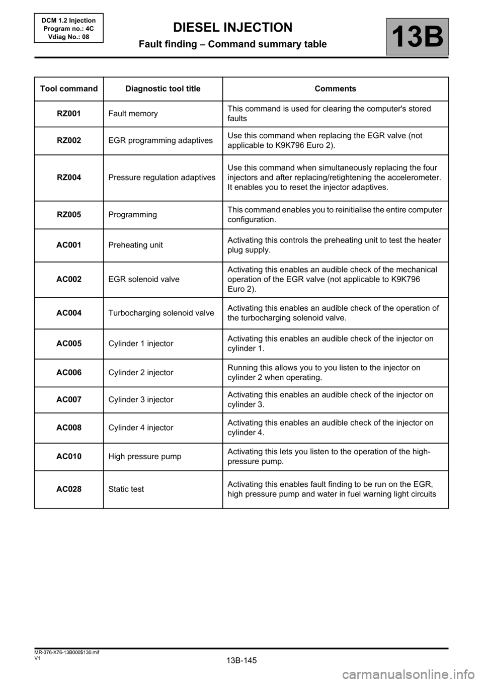
Tool command Diagnostic tool title Comments
RZ001Fault memoryThis command is used for clearing the computer's stored
faults
RZ002EGR programming adaptivesUse this command when replacing the EGR valve (not
applicable to K9K796 Euro 2).
RZ004Pressure regulation adaptivesUse this command when simultaneously replacing the four
injectors and after replacing/retightening the accelerometer.
It enables you to reset the injector adaptives.
RZ005ProgrammingThis command enables you to reinitialise the entire computer
configuration.
AC001Preheating unitActivating this controls the preheating unit to test the heater
plug supply.
AC002EGR solenoid valveActivating this enables an audible check of the mechanical
operation of the EGR valve (not applicable to K9K796
Euro 2).
AC004Turbocharging solenoid valveActivating this enables an audible check of the operation of
the turbocharging solenoid valve.
AC005Cylinder 1 injectorActivating this enables an audible check of the injector on
cylinder 1.
AC006Cylinder 2 injectorRunning this allows you to you listen to the injector on
cylinder 2 when operating.
AC007Cylinder 3 injectorActivating this enables an audible check of the injector on
cylinder 3.
AC008Cylinder 4 injectorActivating this enables an audible check of the injector on
cylinder 4.
AC010High pressure pumpActivating this lets you listen to the operation of the high-
pressure pump.
AC028Static testActivating this enables fault finding to be run on the EGR,
high pressure pump and water in fuel warning light circuits
DIESEL INJECTION
Fault finding – Command summary table
Page 146 of 204
13B-146V1 MR-376-X76-13B000$130.mif
DIESEL INJECTION
Fault finding – Command summary table13B
DCM 1.2 Injection
Program no.: 4C
Vdiag No.: 08
Tool
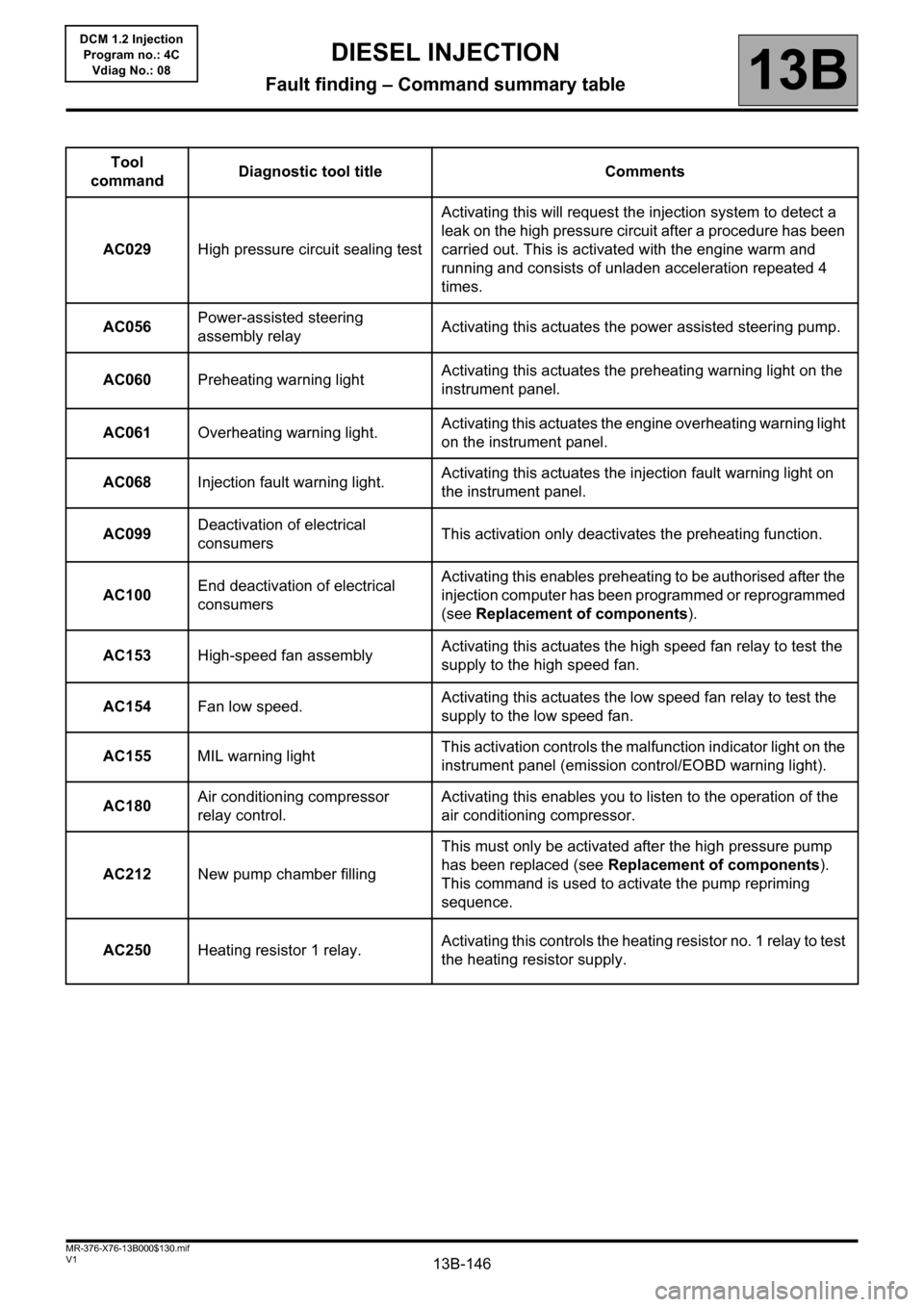
commandDiagnostic tool title Comments
AC029 High pressure circuit sealing testActivating this will request the injection system to detect a
leak on the high pressure circuit after a procedure has been
carried out. This is activated with the engine warm and
running and consists of unladen acceleration repeated 4
times.
AC056 Power-assisted steering
assembly relayActivating this actuates the power assisted steering pump.
AC060 Preheating warning lightActivating this actuates the preheating warning light on the
instrument panel.
AC061 Overheating warning light.Activating this actuates the engine overheating warning light
on the instrument panel.
AC068Injection fault warning light.Activating this actuates the injection fault warning light on
the instrument panel.
AC099Deactivation of electrical
consumersThis activation only deactivates the preheating function.
AC100End deactivation of electrical
consumersActivating this enables preheating to be authorised after the
injection computer has been programmed or reprogrammed
(see Replacement of components).
AC153 High-speed fan assemblyActivating this actuates the high speed fan relay to test the
supply to the high speed fan.
AC154 Fan low speed.Activating this actuates the low speed fan relay to test the
supply to the low speed fan.
AC155MIL warning lightThis activation controls the malfunction indicator light on the
instrument panel (emission control/EOBD warning light).
AC180 Air conditioning compressor
relay control.Activating this enables you to listen to the operation of the
air conditioning compressor.
AC212 New pump chamber fillingThis must only be activated after the high pressure pump
has been replaced (see Replacement of components).
This command is used to activate the pump repriming
sequence.
AC250 Heating resistor 1 relay.Activating this controls the heating resistor no. 1 relay to test
the heating resistor supply.
Page 147 of 204
13B-147V1 MR-376-X76-13B000$130.mif
DIESEL INJECTION
Fault finding – Command summary table13B
DCM 1.2 Injection
Program no.: 4C
Vdiag No.: 08
Tool
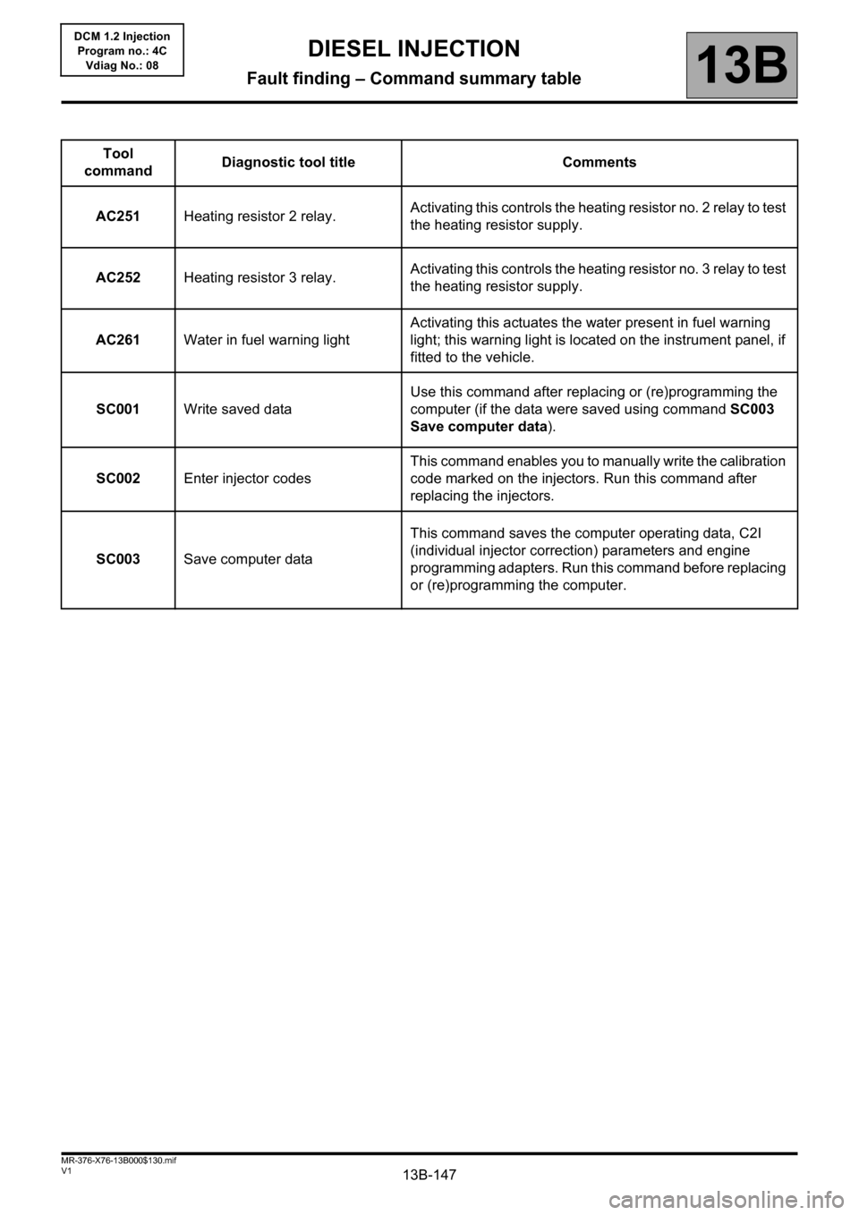
commandDiagnostic tool title Comments
AC251 Heating resistor 2 relay.Activating this controls the heating resistor no. 2 relay to test
the heating resistor supply.
AC252 Heating resistor 3 relay.Activating this controls the heating resistor no. 3 relay to test
the heating resistor supply.
AC261 Water in fuel warning lightActivating this actuates the water present in fuel warning
light; this warning light is located on the instrument panel, if
fitted to the vehicle.
SC001 Write saved dataUse this command after replacing or (re)programming the
computer (if the data were saved using command SC003
Save computer data).
SC002 Enter injector codesThis command enables you to manually write the calibration
code marked on the injectors. Run this command after
replacing the injectors.
SC003 Save computer dataThis command saves the computer operating data, C2I
(individual injector correction) parameters and engine
programming adapters. Run this command before replacing
or (re)programming the computer.
Page 148 of 204
13B-148V1 MR-376-X76-13B000$140.mif
13B
DCM 1.2 Injection
Program no.: 4C
Vdiag No.: 08
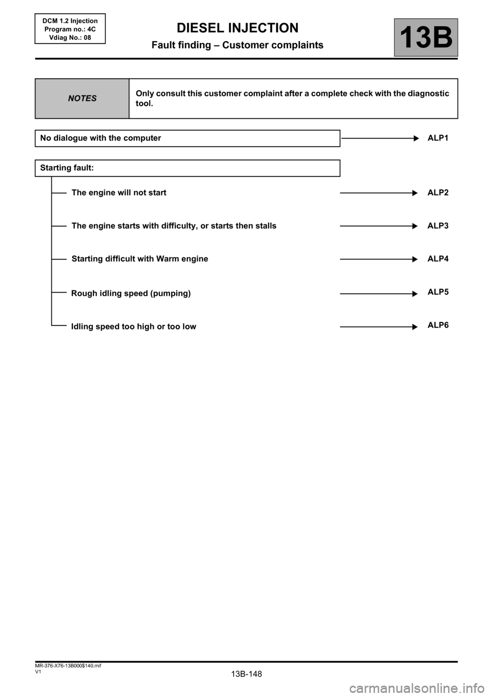
NOTESOnly consult this customer complaint after a complete check with the diagnostic
tool.
No dialogue with the computerALP1
Starting fault:
The engine will not start ALP2
The engine starts with difficulty, or starts then stalls ALP3
Starting difficult with Warm engine ALP4
Rough idling speed (pumping)ALP5
Idling speed too high or too lowALP6
DIESEL INJECTION
Fault finding – Customer complaints
Page 149 of 204

13B-149V1 MR-376-X76-13B000$140.mif
DIESEL INJECTION
Fault finding – Customer complaints13B
DCM 1.2 Injection
Program no.: 4C
Vdiag No.: 08
Behaviour while driving:
Erratic acceleration/deceleration and engine racing ALP7
Acceleration gapALP8
Engine cut-out (stalling)ALP9
Engine buckingALP10
Loss of powerALP11
Too much powerALP 12
Excessive consumptionALP 13
Overspeed when releasing accelerator or changing gearALP 14
Engine dies on pulling awayALP 15
Noise, odours, or smoke:
Engine rattling, noisy engine, turbocharger noise ALP 16
Blue, white or black smoke ALP 17
Smoke (blue, white or black) on accelerationALP 18
Page 150 of 204
13B-150
AFTER REPAIRCarry out a road test followed by a check with the diagnostic tool.
V1 MR-376-X76-13B000$150.mif
13B
DCM 1.2 Injection
Program no.: 4C
Vdiag No.: 08
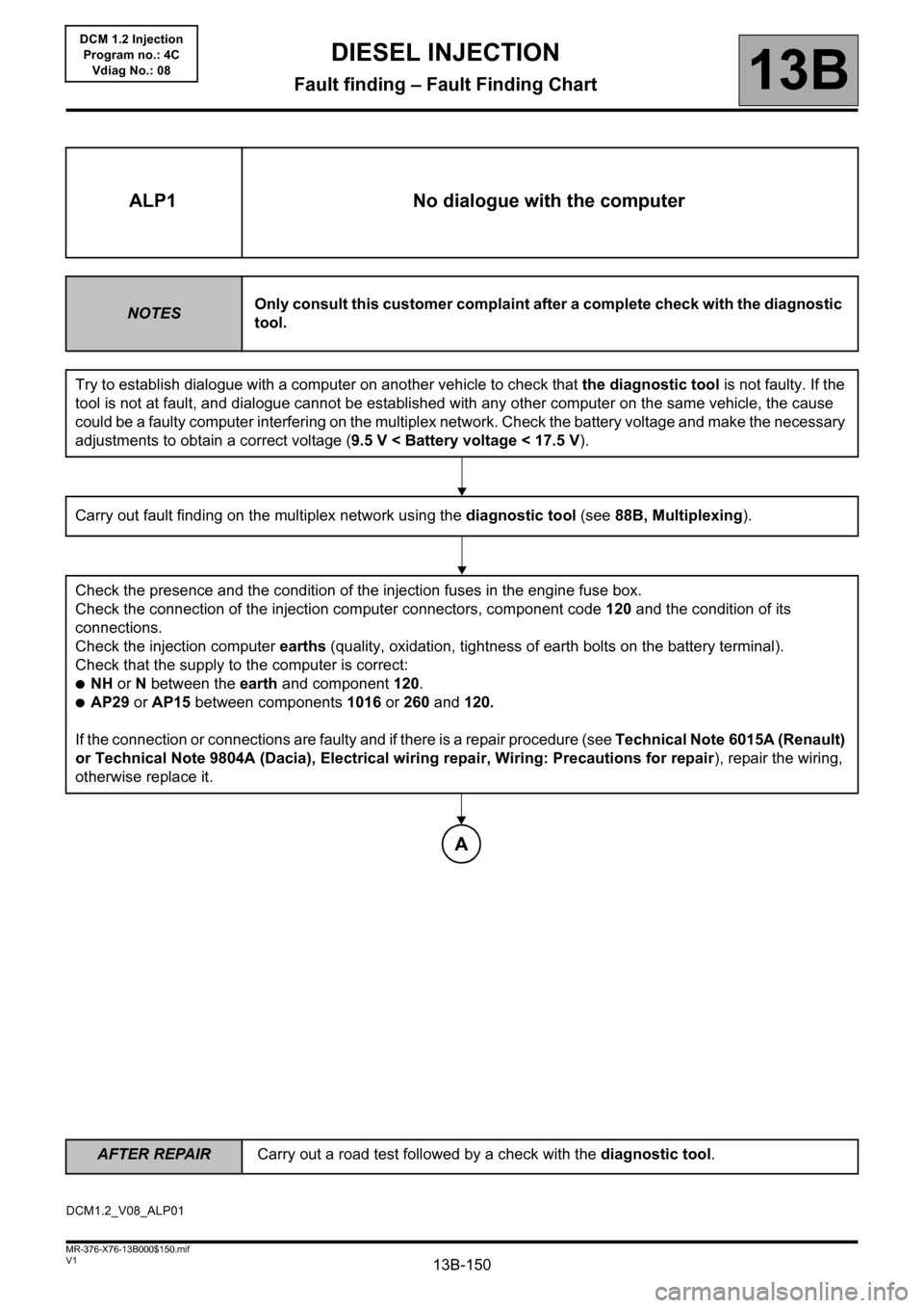
ALP1 No dialogue with the computer
NOTESOnly consult this customer complaint after a complete check with the diagnostic
tool.
Try to establish dialogue with a computer on another vehicle to check that the diagnostic tool is not faulty. If the
tool is not at fault, and dialogue cannot be established with any other computer on the same vehicle, the cause
could be a faulty computer interfering on the multiplex network. Check the battery voltage and make the necessary
adjustments to obtain a correct voltage (9.5 V < Battery voltage < 17.5 V).
Carry out fault finding on the multiplex network using the diagnostic tool (see88B, Multiplexing).
Check the presence and the condition of the injection fuses in the engine fuse box.
Check the connection of the injection computer connectors, component code 120 and the condition of its
connections.
Check the injection computer earths (quality, oxidation, tightness of earth bolts on the battery terminal).
Check that the supply to the computer is correct:
●NH or N between the earth and component 120.
●AP29 or AP15 between components 1016 or 260 and 120.
If the connection or connections are faulty and if there is a repair procedure (see Technical Note 6015A (Renault)
or Technical Note 9804A (Dacia), Electrical wiring repair, Wiring: Precautions for repair), repair the wiring,
otherwise replace it.
A
DCM1.2_V08_ALP01
DIESEL INJECTION
Fault finding – Fault Finding Chart