torque SSANGYONG MUSSO 1998 Workshop Repair Manual
[x] Cancel search | Manufacturer: SSANGYONG, Model Year: 1998, Model line: MUSSO, Model: SSANGYONG MUSSO 1998Pages: 1463, PDF Size: 19.88 MB
Page 806 of 1463

1G3-4 OM600 ENGINE INTAKE & EXHAUST
Removal & Installation Procedure
1. Loosen the air duct hose clamp and then remove the air
cleaner and air duct hose.
2. Disconnect the air cleaner housing cover clamp and remove
the cover and element.
Tightening Torque 9 - 11 Nm 3. Loosen the nut (4EA) and remove the air cleaner housing
from the intake manifold.
Notice
Do not fold the rubber.
Operating IntervalClean
Replaceevery 20,000km
every 60,000km
4. Loosen the clamp and remove the air duct hose.
5. Loosen the mounting nut and bolt.
6. Remove the air inlet duct and hose.
7. Installation should follow the removal procedure in the
reverse order.
Page 809 of 1463

OM600 ENGINE INTAKE & EXHAUST 1G3-7
Removal & Installation Procedure
1. Remove the bolt from the exhaust manifold and then remove
the front exhaust pipe.
Installation Notice
Tightening Torque 15 - 18 Nm
Notice
When tightening the nut(3), maintain the clearance between
exhaust manifold(1) and front exhaust pipe.
2. Remove the nut from the front of center muffler and then
remove the front exhaust pipe.
Installation Notice
3. Remove the nut from the rear of center muffler and then
remove the tail muffler.
Installation Notice
4. Remove the muffler mounting hanger from the rubber pad
and remove the center muffler and tail muffler.
Notice
Check the gasket, if necessary, replace the new one.
5. Installation should follow the removal procedure in the
reverse order.
Tightening Torque 28 - 47 Nm
Tightening Torque 28 - 47 Nm
Page 839 of 1463

2C-2 FRONT SUSPENSION
Application
Torque Arm BoltNlm
40 - 60
60 - 80
FASTENER TIGHTENING SPECIFICATIONS
Stabilizer Bar
Application
Stabilizer Bar Retaining Nut
Stabilizer Bar Link Nut
Lower Arm NutNlm
30 - 45
60 - 80
16 - 22
Torsion Bar
Lower and Upper Arm
Application
Upper Arm Nut
Upper Arm End Castle Nut
Lower Arm Nut
Lower Arm End Castle NutNlm
120 - 140
80 - 150
150 - 180
120 - 180
Steering Knuckle and Drive Shaft
Application
Brake Caliper Hose Bolt
Brake Caliper Mounting Bolt
Tie Rod Retaining Nut
Upper Arm Retaining Nut
Lower Arm Retaining NutNlm
25 - 35
85 - 105
35 - 45
80 - 150
120 - 180
M10
M12
Page 842 of 1463
FRONT SUSPENSION 2C-5
Removal & Installation Procedure
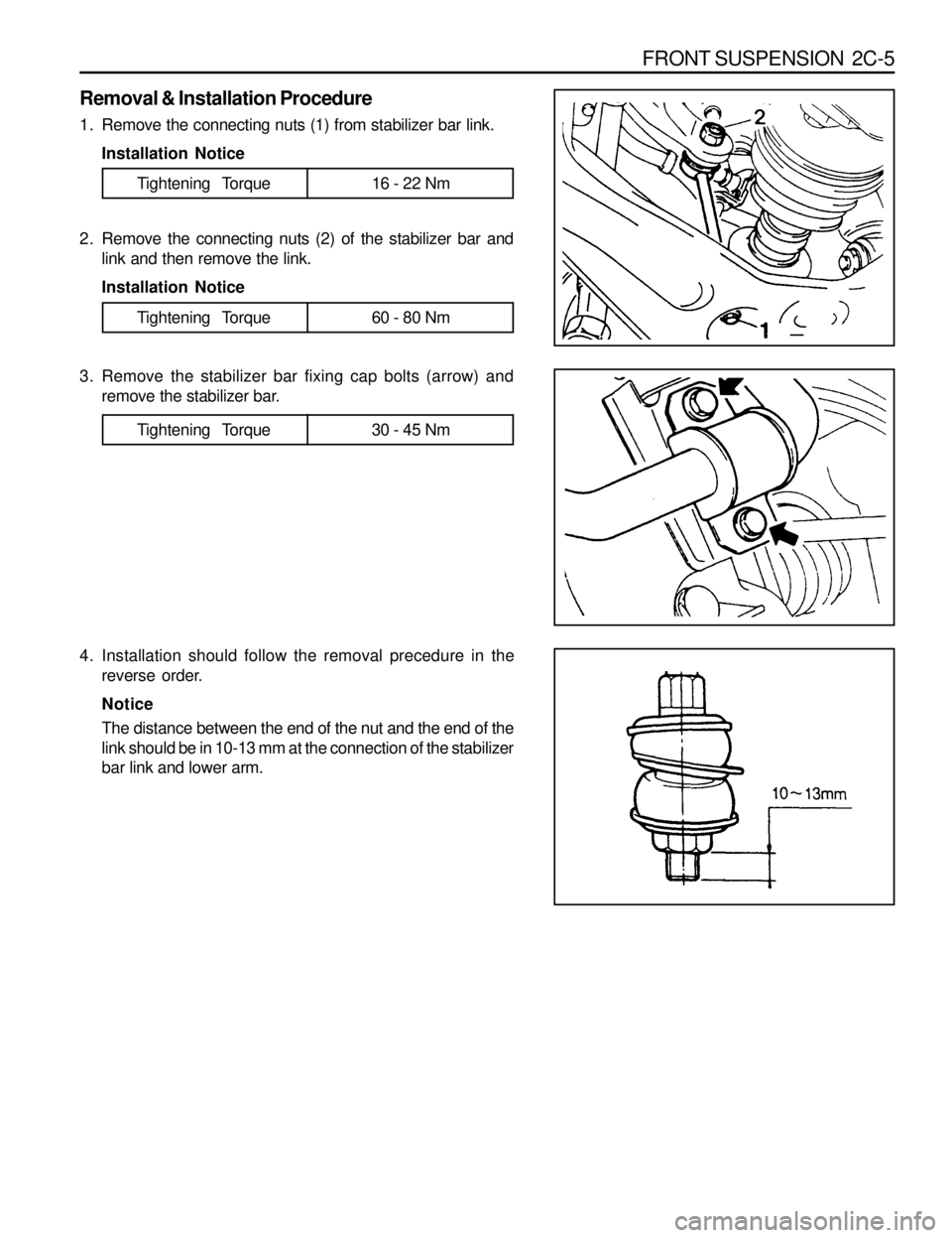
1. Remove the connecting nuts (1) from stabilizer bar link.
Installation Notice
2. Remove the connecting nuts (2) of the stabilizer bar and
link and then remove the link.
Installation Notice
3. Remove the stabilizer bar fixing cap bolts (arrow) and
remove the stabilizer bar.
Tightening Torque 60 - 80 Nm
4. Installation should follow the removal precedure in the
reverse order.
Notice
The distance between the end of the nut and the end of the
link should be in 10-13 mm at the connection of the stabilizer
bar link and lower arm.
Tightening Torque 30 - 45 Nm
Tightening Torque 16 - 22 Nm
Page 843 of 1463
2C-6 FRONT SUSPENSION
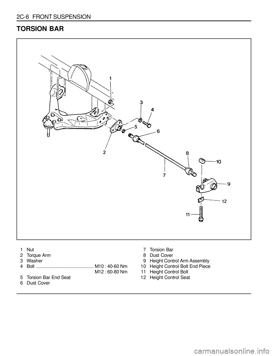
TORSION BAR
1 Nut
2 Torque Arm
3 Washer
4 Bolt............................................M10 : 40-60 Nm
M12 : 60-80 Nm
5 Torsion Bar End Seat
6 Dust Cover7 Torsion Bar
8 Dust Cover
9 Height Control Arm Assembly
10 Height Control Bolt End Piece
11 Height Control Bolt
12 Height Control Seat
Page 844 of 1463

FRONT SUSPENSION 2C-7
Removal & Installation Procedure
1. Remove the fixing nuts and bolts of the shock absorber
and lower arm connection.
Installation Notice
2. Remove the connecting nuts of the stabilizer bar link to the
lower arm.
Installation Notice
3. Turn the height control bolt until the distance between the
end of the height control bolt end piece and the bolt end
becomes 0-5 mm.
Installation Notice
Install the torsion bar spring and adjust the distance between
the end of the height control bolt and piece end the bolt
end to be 50-55 mm. Adjust the vehicle height.
Tightening Torque 60 - 80 Nm
Tightening Torque 16 - 22 Nm
4. Remove the torque arm fixing nuts and bolts and then
withdraw the torsion bar spring.
Installation Notice
M10
M12Tightening Torque40 - 60 Nm
60 - 80 Nm
5. Installation should follow the removal precedure in the
reverse order.
6. Check and adjust the wheel alignment.
Page 846 of 1463
FRONT SUSPENSION 2C-9
Removal & Installation Procedure
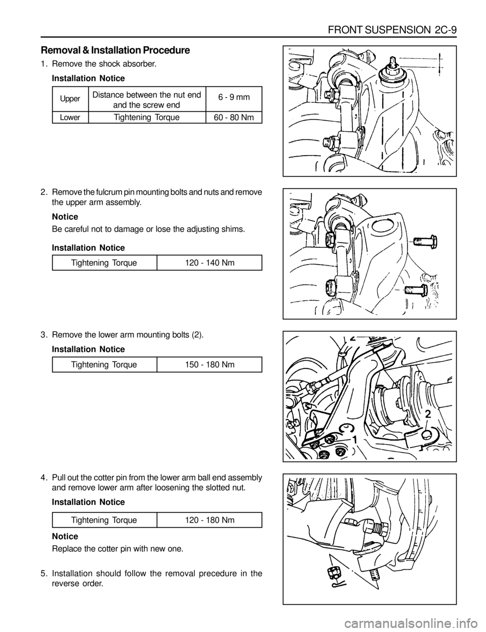
1. Remove the shock absorber.
Installation Notice
2. Remove the fulcrum pin mounting bolts and nuts and remove
the upper arm assembly.
Notice
Be careful not to damage or lose the adjusting shims.
Upper
LowerDistance between the nut end
and the screw end
Tightening Torque6 - 9 mm
60 - 80 Nm
3. Remove the lower arm mounting bolts (2).
Installation Notice
Tightening Torque 120 - 140 Nm
4. Pull out the cotter pin from the lower arm ball end assembly
and remove lower arm after loosening the slotted nut.
Installation Notice
Tightening Torque 150 - 180 Nm
Notice
Replace the cotter pin with new one.
5. Installation should follow the removal precedure in the
reverse order.
Tightening Torque 120 - 180 Nm
Installation Notice
Page 850 of 1463

FRONT SUSPENSION 2C-13
VERTICAL AND LATERAL SENSOR
Removal & Installation Procedure
1. Disconnect vertical sensor and lateral sensor connectors.
Notice
When connecting the connectors, connector connection of
the lateral sensor (2) should be in the right and connector
connection of the vertical sensor (1) should face downward.
2. Unscrew bolts and remove vertical sensor and lateral sensor.
Installation Notice
1 Body Vertical Acceleration Sensor(Vertical Sensor)
2 Body Lateral Acceleration Sensor (Lateral Sensor)
3. Installation should follow the removal procedure in the
reverse order.
Tightening Torque 20 - 30 Nm
Page 857 of 1463
2D-6 REAR SUSPENSION
Removal & Installation Procedure
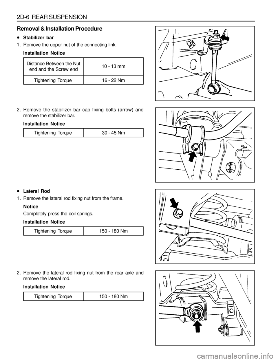
lStabilizer bar
1. Remove the upper nut of the connecting link.
Installation Notice
2. Remove the stabilizer bar cap fixing bolts (arrow) and
remove the stabilizer bar.
Installation Notice
Tightening Torque 16 - 22 Nm
Distance Between the Nut
end and the Screw end10 - 13 mm
Tightening Torque 30 - 45 Nm
lLateral Rod
1. Remove the lateral rod fixing nut from the frame.
Notice
Completely press the coil springs.
Installation Notice
2. Remove the lateral rod fixing nut from the rear axle and
remove the lateral rod.
Installation Notice
Tightening Torque 150 - 180 Nm
Tightening Torque 150 - 180 Nm
Page 858 of 1463
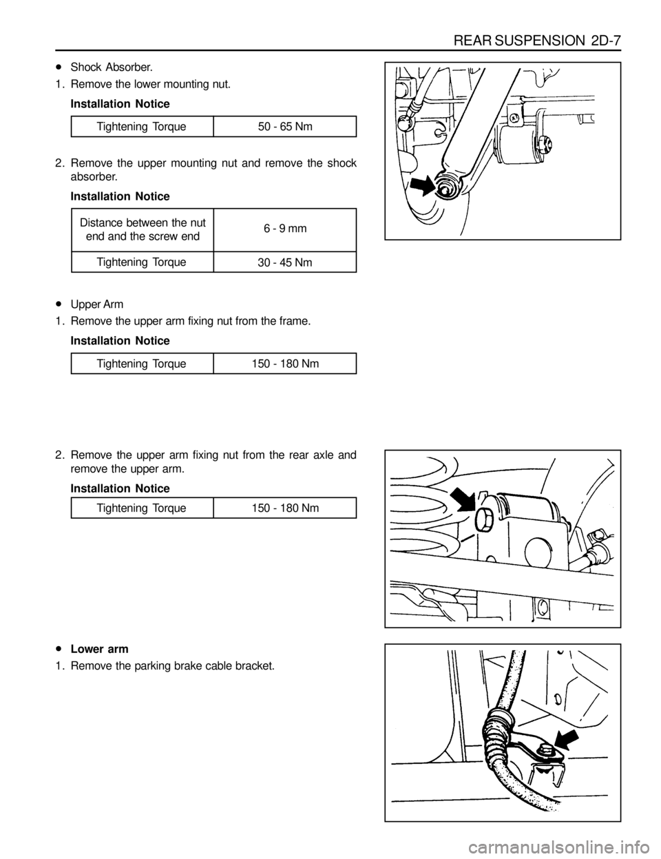
REAR SUSPENSION 2D-7
lShock Absorber.
1. Remove the lower mounting nut.
Installation Notice
2. Remove the upper mounting nut and remove the shock
absorber.
Installation Notice
Tightening Torque 50 - 65 Nm
lUpper Arm
1. Remove the upper arm fixing nut from the frame.
Installation Notice
2. Remove the upper arm fixing nut from the rear axle and
remove the upper arm.
Installation Notice
Tightening Torque 150 - 180 Nm
Tightening Torque 150 - 180 Nm
lLower arm
1. Remove the parking brake cable bracket.
Tightening Torque
30 - 45 Nm
Distance between the nut
end and the screw end6 - 9 mm