SUBARU FORESTER 2004 Service Repair Manual
Manufacturer: SUBARU, Model Year: 2004, Model line: FORESTER, Model: SUBARU FORESTER 2004Pages: 2870, PDF Size: 38.67 MB
Page 1021 of 2870
CO(H4SO)-38
COOLING
Radiator Main Fan and Fan Motor
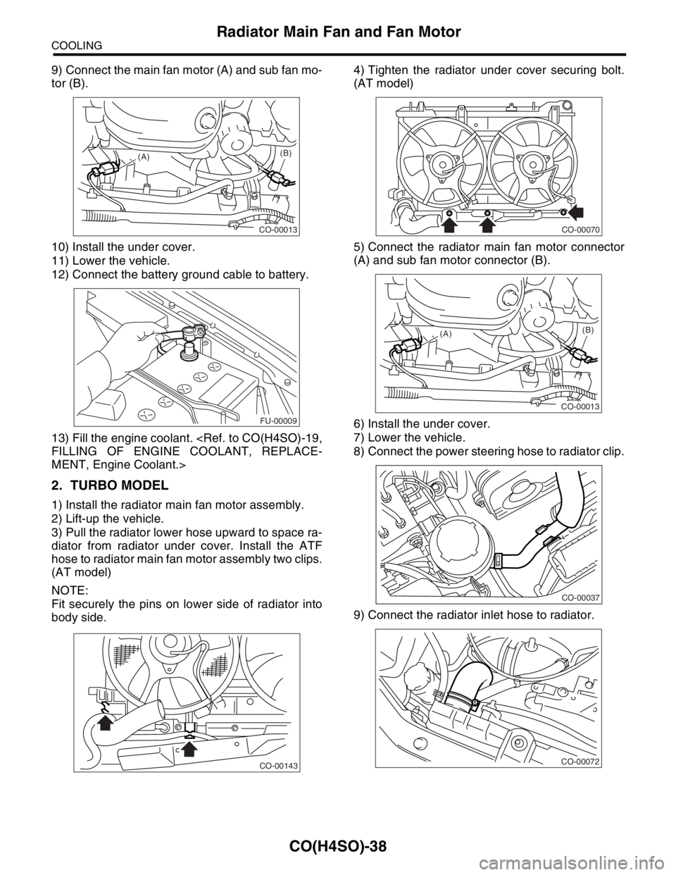
9) Connect the main fan motor (A) and sub fan mo-
tor (B).
10) Install the under cover.
11) Lower the vehicle.
12) Connect the battery ground cable to battery.
13) Fill the engine coolant.
MENT, Engine Coolant.>
2. TURBO MODEL
1) Install the radiator main fan motor assembly.
2) Lift-up the vehicle.
3) Pull the radiator lower hose upward to space ra-
diator from radiator under cover. Install the ATF
hose to radiator main fan motor assembly two clips.
(AT model)
NOTE:
Fit securely the pins on lower side of radiator into
body side.4) Tighten the radiator under cover securing bolt.
(AT model)
5) Connect the radiator main fan motor connector
(A) and sub fan motor connector (B).
6) Install the under cover.
7) Lower the vehicle.
8) Connect the power steering hose to radiator clip.
9) Connect the radiator inlet hose to radiator.
CO-00013
(A)(B)
FU-00009
CO-00143
CO-00070
CO-00013
(A)(B)
CO-00037
CO-00072
Page 1022 of 2870
CO(H4SO)-39
COOLING
Radiator Main Fan and Fan Motor
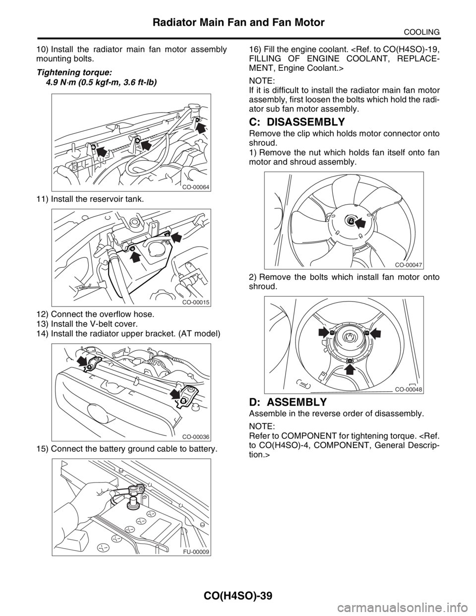
10) Install the radiator main fan motor assembly
mounting bolts.
Tightening torque:
4.9 N
⋅m (0.5 kgf-m, 3.6 ft-lb)
11) Install the reservoir tank.
12) Connect the overflow hose.
13) Install the V-belt cover.
14) Install the radiator upper bracket. (AT model)
15) Connect the battery ground cable to battery.16) Fill the engine coolant.
MENT, Engine Coolant.>
NOTE:
If it is difficult to install the radiator main fan motor
assembly, first loosen the bolts which hold the radi-
ator sub fan motor assembly.
C: DISASSEMBLY
Remove the clip which holds motor connector onto
shroud.
1) Remove the nut which holds fan itself onto fan
motor and shroud assembly.
2) Remove the bolts which install fan motor onto
shroud.
D: ASSEMBLY
Assemble in the reverse order of disassembly.
NOTE:
Refer to COMPONENT for tightening torque.
tion.>
CO-00064
CO-00015
CO-00036
FU-00009
CO-00047
CO-00048
Page 1023 of 2870
CO(H4SO)-40
COOLING
Radiator Sub Fan and Fan Motor
9. Radiator Sub Fan and Fan
Motor
A: REMOVAL
Refer to Radiator Main Fan and Fan Motor.
Fan Motor.>
B: INSTALLATION
Refer to Radiator Main Fan and Fan Motor.
Fan and Fan Motor.>
C: DISASSEMBLY
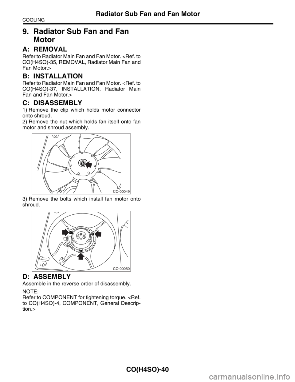
1) Remove the clip which holds motor connector
onto shroud.
2) Remove the nut which holds fan itself onto fan
motor and shroud assembly.
3) Remove the bolts which install fan motor onto
shroud.
D: ASSEMBLY
Assemble in the reverse order of disassembly.
NOTE:
Refer to COMPONENT for tightening torque.
tion.>
CO-00049
CO-00050
Page 1024 of 2870
CO(H4SO)-41
COOLING
Reservoir Tank
10.Reservoir Tank
A: REMOVAL
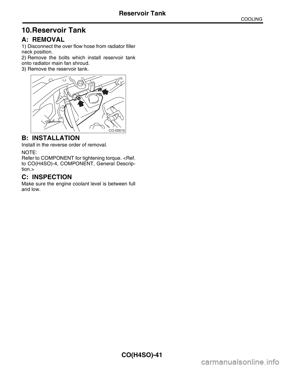
1) Disconnect the over flow hose from radiator filler
neck position.
2) Remove the bolts which install reservoir tank
onto radiator main fan shroud.
3) Remove the reservoir tank.
B: INSTALLATION
Install in the reverse order of removal.
NOTE:
Refer to COMPONENT for tightening torque.
tion.>
C: INSPECTION
Make sure the engine coolant level is between full
and low.
CO-00015
Page 1025 of 2870
CO(H4SO)-42
COOLING
Coolant Filler Tank
11.Coolant Filler Tank
A: REMOVAL
WARNING:
The radiator is pressurized. Wait until the en-
gine cools down before working on the radia-
tor.
1) Drain the coolant about 3.02 (3.2 US qt, 2.6 Imp
qt).
ant.>
2) Remove the air cleaner upper cover and air in-
take boot.
3) Remove the air cleaner element.
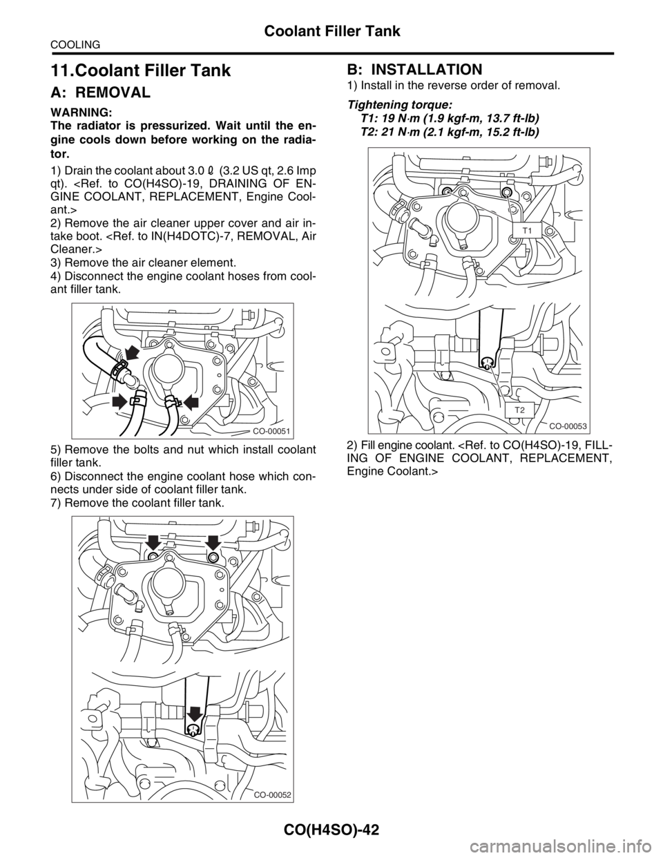
4) Disconnect the engine coolant hoses from cool-
ant filler tank.
5) Remove the bolts and nut which install coolant
filler tank.
6) Disconnect the engine coolant hose which con-
nects under side of coolant filler tank.
7) Remove the coolant filler tank.
B: INSTALLATION
1) Install in the reverse order of removal.
Tightening torque:
T1: 19 N
⋅m (1.9 kgf-m, 13.7 ft-lb)
T2: 21 N
⋅m (2.1 kgf-m, 15.2 ft-lb)
2) Fill engine coolant.
Engine Coolant.>
CO-00051
CO-00052
T2
T1
CO-00053
Page 1026 of 2870

CO(H4SO)-43
COOLING
Engine Cooling System Trouble in General
12.Engine Cooling System Trouble in General
A: INSPECTION
Trouble Possible cause Corrective action
Over-heatinga. Insufficient engine coolantReplenish the engine coolant, inspect for leakage, and
repair.
b. Loose timing belt Repair or replace the timing belt tensioner.
c. Oil on drive belt Replace.
d. Malfunction of thermostat Replace.
e. Malfunction of water pump Replace.
f. Clogged engine coolant passage Clean.
g. Improper ignition timingInspect and repair the ignition control system.
h. Clogged or leaking radiator Clean or repair, or replace.
i. Improper engine oil in engine coolant Replace the engine coolant.
j. Air/fuel mixture ratio too leanInspect and repair the fuel injection system.
k. Excessive back pressure in exhaust system Clean or replace.
l. Insufficient clearance between piston and cylinder Adjust or replace.
m. Slipping clutch Repair or replace.
n. Dragging brake Adjust.
o. Defective thermostat Replace.
p. Malfunction of radiator fanInspect the radiator fan relay, engine coolant tempera-
ture sensor or radiator motor and replace there.
Over-coolinga. Atmospheric temperature extremely low Partly cover the radiator front area.
b. Defective thermostat Replace.
Engine coolant
leaks.a. Loosened or damaged connecting units on hoses Repair or replace.
b. Leakage from water pump Replace.
c. Leakage from water pipe Repair or replace.
d. Leakage around cylinder head gasket Retighten the cylinder head bolts or replace gasket.
e. Damaged or cracked cylinder head and crankcase Repair or replace.
f. Damaged or cracked thermostat case Repair or replace.
g. Leakage from radiator Repair or replace.
Noisea. Defective drive belt Replace.
b. Defective radiator fan Replace.
c. Defective water pump bearing Replace the water pump.
d. Defective water pump mechanical seal Replace the water pump.
Page 1027 of 2870

CO(H4SO)-44
COOLING
Engine Cooling System Trouble in General
Page 1028 of 2870
FUJI HEAVY INDUSTRIES LTD. G8080GE2
2004 FORESTER SERVICE MANUAL QUICK REFERENCE INDEX
ENGINE SECTION 1
This service manual has been prepared
to provide SUBARU service personnel
with the necessary information and data
for the correct maintenance and repair
of SUBARU vehicles.
This manual includes the procedures
for maintenance, disassembling, reas-
sembling, inspection and adjustment of
components and diagnostics for guid-
ance of experienced mechanics.
Please peruse and utilize this manual
fully to ensure complete repair work for
satisfying our customers by keeping
their vehicle in optimum condition.
When replacement of parts during
repair work is needed, be sure to use
SUBARU genuine parts.
All information, illustration and specifi-
cations contained in this manual are
based on the latest product information
available at the time of publication
approval.FUEL INJECTION (FUEL SYSTEM) FU(H4SO)
EMISSION CONTROL
(AUX. EMISSION CONTROL DEVICE)EC(H4SO)
INTAKE (INDUCTION) IN(H4SO)
MECHANICAL ME(H4SO)
EXHAUST EX(H4SO)
COOLING CO(H4SO)
LUBRICATION LU(H4SO)
SPEED CONTROL SYSTEM SP(H4SO)
IGNITION IG(H4SO)
STARTING/CHARGING SYSTEM SC(H4SO)
ENGINE (DIAGNOSTIC) EN(H4SO)
Page 1029 of 2870

LUBRICATION
LU(H4SO)
Page
1. General Description ....................................................................................2
2. Oil Pressure System ...................................................................................8
3. Engine Oil..................................................................................................10
4. Oil Pump ...................................................................................................12
5. Oil Pan and Strainer ..................................................................................16
6. Oil Pressure Switch ...................................................................................20
7. Engine Oil Cooler ......................................................................................21
8. Engine Oil Filter.........................................................................................23
9. Engine Lubrication System Trouble in General.........................................24
Page 1030 of 2870

LU(H4SO)-2
LUBRICATION
General Description
1. General Description
A: SPECIFICATION
Lubrication methodForced lubrication
Oil pumpPump type Trochoid type
Number of teethInner rotor 9
Outer rotor 10
Outer rotor diameter×thicknessNon-turbo model 78×7 mm (3.07×0.28 in)
Turbo model 78×10 mm (3.07×0.39 in)
Tip clearance between inner and outer rotorStandard 0.04 — 0.14 mm (0.0016 — 0.0055 in)
Limit 0.18 mm (0.0071 in)
Side clearance between inner rotor and pump
caseStandard 0.02 — 0.07 mm (0.0008 — 0.0028 in)
Limit 0.12 mm (0.0047 in)
Case clearance between outer rotor and pump
caseStandard 0.10 — 0.175 mm (0.0039 — 0.0069 in)
Limit 0.20 mm (0.0079 in)
Capacity at
80°C (176°F)Non-turbo
model
600 rpmDischarge
pressure98 kPa (1.0 kg/cm
2, 14 psi)
Discharge
quantity3.22 (3.4 US qt, 2.8 Imp qt)/min.
5,000 rpmDischarge
pressure294 kPa (3.0 kg/cm
2, 43 psi)
Discharge
quantity32.62 (34.4 US qt, 28.7 Imp qt)/min.
Turbo model
600 rpmDischarge
pressure98 kPa (1.0 kg/cm
2, 14 psi)
Discharge
quantity4.62 (4.9 US qt, 4.0 Imp qt)/min.
5,000 rpmDischarge
pressure294 kPa (3.0 kg/cm
2, 43 psi)
Discharge
quantity47.02 (49.7 US qt, 41.4 Imp qt)/min.
Relief valve operation pressureNon-turbo model
490 kPa (5.0 kg/cm
2, 71 psi)
Turbo model
588 kPa (6.0 kg/cm
2, 85 psi)
Oil filterTy p eFull-flow filter type
Filtration areaNon-turbo
760 cm
2 (118 sq in)
Tu r b o
800 cm
2 (124 sq in)
By-pass valve opening pressureNon-turbo
157 kPa (1.60 kg/cm
2, 22.8 psi)
Tu r b o
160 kPa (1.63 kg/cm
2, 23.2 psi)
Outer diameter×widthNon-turbo 80×70 mm (3.15×2.76 in)
Tu r b o 6 8×65 mm (2.68×2.56 in)
Oil filter to engine thread size M 20×1.5
Oil pressure
switchType Immersed contact point type
Working voltage — wattage 12 V — 3.4 W or less
Warning light activation pressure
14.7 kPa (0.15 kg/cm
2, 2.1 psi)
Proof pressure
More than 981 kPa (10 kg/cm
2, 142 psi)
Oil capacity (at replacement) 4.02 (4.2 US qt, 3.5 Imp qt)