SUBARU FORESTER 2004 Service Repair Manual
Manufacturer: SUBARU, Model Year: 2004, Model line: FORESTER, Model: SUBARU FORESTER 2004Pages: 2870, PDF Size: 38.67 MB
Page 991 of 2870

CO(H4SO)-8
COOLING
General Description
TURBO MODEL
CO-00140 (9)
(1)(10)(8)
(2)
T3
T2
T4(14)
(20) (22)(3) (4)
(19)(7)
(12)
(11)
(13)
T5
T5
T1
T1
(5) (5)(5)(5)
(5)(6)
(21) (27)
(25)(24)
(23)
(26)
(5)
B
C
B
C
T2(16) (18)(17)
(15) (15)
(15)
(15)
T3
T2
T3
(32) (31)
B
C
(15)
(33)
(28)(29)
(33)
(34)
(34)
(35)(35)
(30) (15)(15)
T4
Page 992 of 2870

CO(H4SO)-9
COOLING
General Description
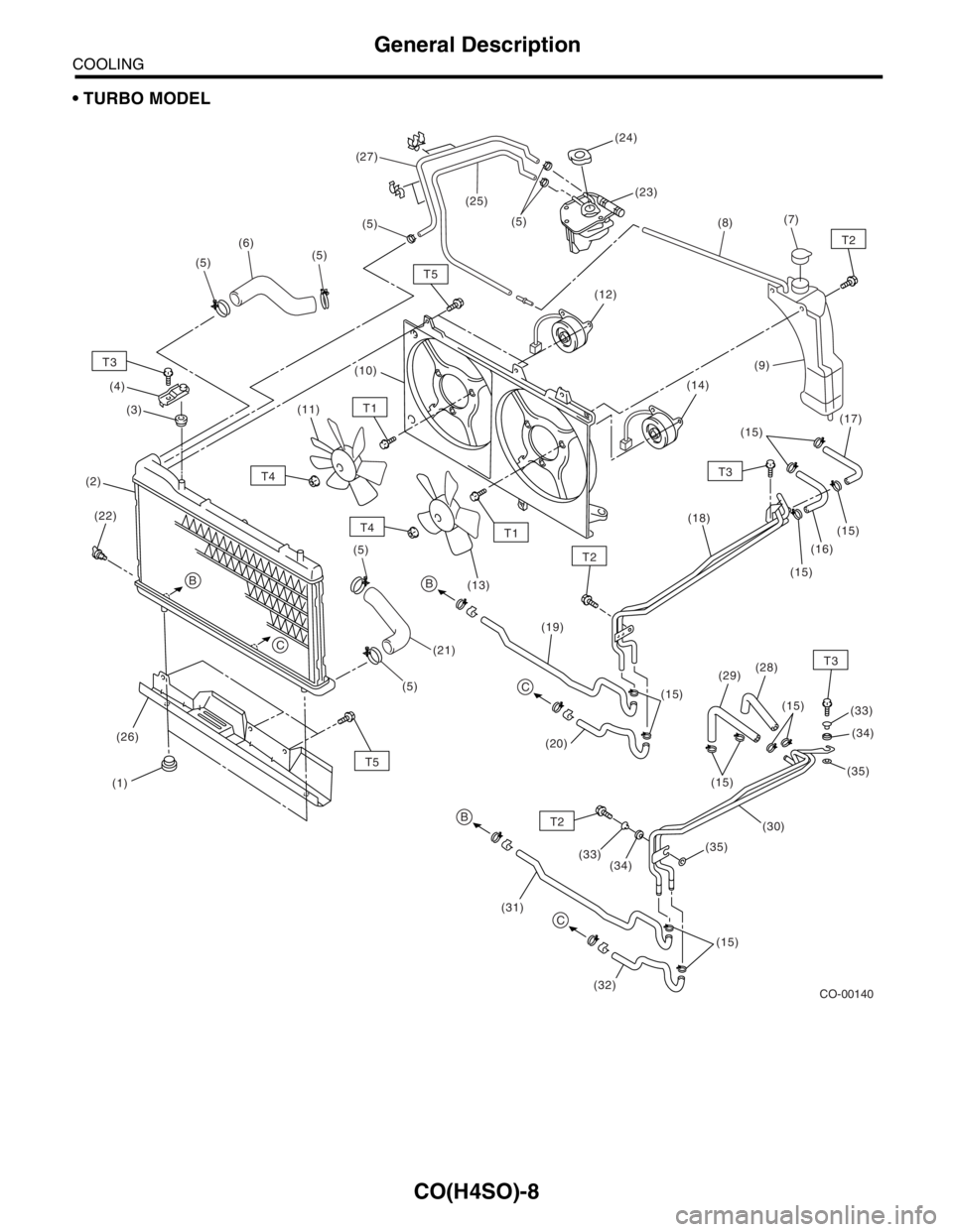
(1) Radiator lower cushion (18) ATF pipe (AT model) (31) Oil cooler inlet hose B (MT model
with oil cooler)
(2) Radiator (19) ATF inlet hose B (AT model)
(3) Radiator upper cushion (20) ATF outlet hose B (AT model) (32) Oil cooler outlet hose B (MT
model with oil cooler)
(4) Radiator upper bracket (21) Radiator outlet hose
(5) Clamp (22) Radiator drain plug (33) Spacer (MT model with oil cooler)
(6) Radiator inlet hose (23) Engine coolant filler tank (34) Cushion (MT model with oil
cooler)
(7) Engine coolant reservoir tank cap (24) Engine coolant filler tank cap
(8) Over flow hose (25) Engine overflow hose (35) Setting washer (MT model with oil
cooler)
(9) Engine coolant reservoir tank (26) Radiator under cover (AT model)
(10) Radiator fan shroud (27) Engine air breather hose
(11) Radiator sub fan (28) Oil cooler inlet hose A (MT model
with oil cooler)Tightening torque: N
⋅m (kgf-m, ft-lb)
(12) Radiator sub fan motorT1: 4.4 (0.45, 3.3)
(13) Radiator main fan (29) Oil cooler outlet hose A (MT
model with oil cooler)T2: 7.5 (0.76, 5.5)
(14) Radiator main fan motorT3: 18 (1.8, 13.0)
(15) ATF hose clamp (AT model) (30) Oil cooler pipe (MT model with oil
cooler)T4: 3.4 (0.35, 2.5)
(16) ATF inlet hose A (AT model)T5: 4.9 (0.50, 3.6)
(17) ATF outlet hose A (AT model)
Page 993 of 2870

CO(H4SO)-10
COOLING
General Description
C: CAUTION
Wear working clothing, including a cap, protec-
tive goggles, and protective shoes during opera-
tion.
Remove contamination including dirt and corro-
sion before removal, installation or disassembly.
Keep the disassembled parts in order and pro-
tect them from dust or dirt.
Before removal, installation or disassembly, be
sure to clarify the failure. Avoid unnecessary re-
moval, installation, disassembly, and replacement.
Be careful not to burn your hands, because each
part in the vehicle is hot after running.
Be sure to tighten fasteners including bolts and
nuts to the specified torque.
Place shop jacks or rigid racks at the specified
points.
Before disconnecting electrical connectors of
sensors or units, be sure to disconnect the ground
cable from battery.
Page 994 of 2870

CO(H4SO)-11
COOLING
General Description
D: PREPARATION TOOL
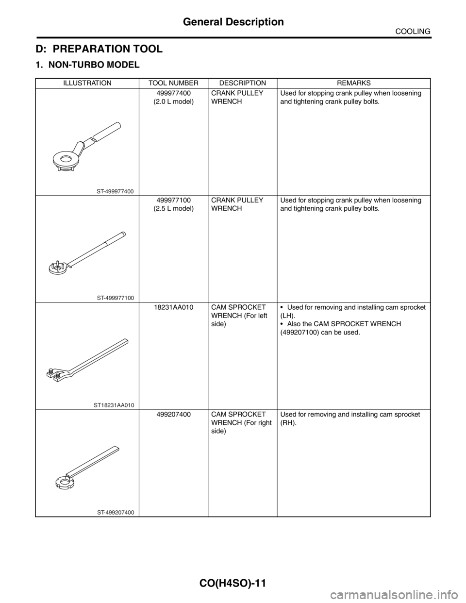
1. NON-TURBO MODEL
ILLUSTRATION TOOL NUMBER DESCRIPTION REMARKS
499977400
(2.0 L model)CRANK PULLEY
WRENCHUsed for stopping crank pulley when loosening
and tightening crank pulley bolts.
499977100
(2.5 L model)CRANK PULLEY
WRENCHUsed for stopping crank pulley when loosening
and tightening crank pulley bolts.
18231AA010 CAM SPROCKET
WRENCH (For left
side) Used for removing and installing cam sprocket
(LH).
Also the CAM SPROCKET WRENCH
(499207100) can be used.
499207400 CAM SPROCKET
WRENCH (For right
side)Used for removing and installing cam sprocket
(RH).
ST-499977400
ST-499977100
ST18231AA010
ST-499207400
Page 995 of 2870

CO(H4SO)-12
COOLING
General Description
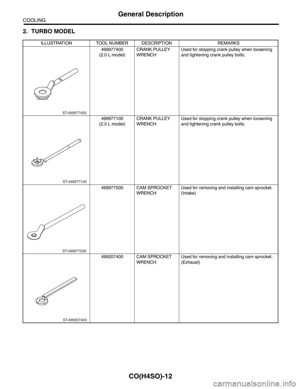
2. TURBO MODEL
ILLUSTRATION TOOL NUMBER DESCRIPTION REMARKS
499977400
(2.0 L model)CRANK PULLEY
WRENCHUsed for stopping crank pulley when loosening
and tightening crank pulley bolts.
499977100
(2.5 L model)CRANK PULLEY
WRENCHUsed for stopping crank pulley when loosening
and tightening crank pulley bolts.
499977500 CAM SPROCKET
WRENCHUsed for removing and installing cam sprocket.
(Intake)
499207400 CAM SPROCKET
WRENCHUsed for removing and installing cam sprocket.
(Exhaust)
ST-499977400
ST-499977100
ST-499977500
ST-499207400
Page 996 of 2870

CO(H4SO)-13
COOLING
Radiator Fan System
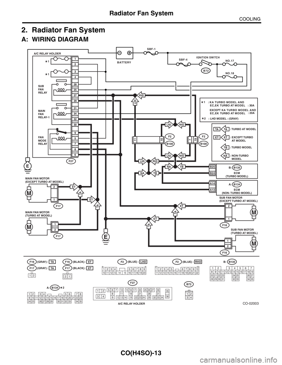
2. Radiator Fan System
A: WIRING DIAGRAM
CO-02003
B72 SBF-1
SBF-4
NO.17
NO.18
MAIN FAN MOTOR
(EXCEPT TURBO AT MODEL)
F17
2
1
ET
MAIN
FA N
RELAY-1
FA N
MODE
RELAY31
34
32
30
5
9
7
8
6 SUB
FA N
RELAY A/C RELAY HOLDER
28
25
3
4
27
29
RHD
RHD
RHD
RHDLHD
LHD
LHD
F2
B1001110F2
B100197
2
1
F27
B25
B24
A14
ECM
(NON- TURBO MODEL)B134 A:
A13
NA
F17
F16
21
LHD
RHD
F2(BLACK)
(BLACK) (GRAY)
(GRAY)F2
A/C RELAY HOLDER
F27
12
34
567891110
1312142120
2322243130
333234
1615171819
26252728293536
B:B135
A:
B134
1234567891011121314151617181920212223242526272829303132333435
: : ::
ET
TA
1234 5678910 11 12 13 14 15 16 17 18 19 2012345
678910
11 12 19 20 2113 14 15 16 17 18 22
B135 B:
ECM
(TURBO MODEL)
(BLUE)
(BLUE)
567 2 134
2910
1112131415252416
30
98171819202821222332312627333435
: TURBO MODELTB
: NON-TURBO
MODEL
NA: TURBO AT MODEL
TA
: EXCEPT TURBO
AT MODEL
ET
: KA TURBO MODEL AND
EC,EK TURBO AT MODEL : 30A 1*
1*
1*
: LHD MODEL : (GRAY) 2*
2*
SUB FAN MOTOR
(TURBO AT MODEL)
F16
1
2
MAIN FAN MOTOR
(TURBO AT MODEL)
F17
1
2
SUB FAN MOTOR
(EXCEPT TURBO AT MODEL)
F16
2
1
TA
ET
TA
TA
LHD
TA
ET
ET
TBNA
TB
12
F17
F16TA
:
TA
ET
:
ET
E
EXCEPT KA TURBO MODEL AND
EC,EK TURBO AT MODEL: 20A
IGNITION SWITCH
BATTERY
3412
B72
Page 997 of 2870

CO(H4SO)-14
COOLING
Radiator Fan System
B: INSPECTION
DETECTING CONDITION:
Engine coolant temperature is above 95°C (203°F).
Vehicle speed is below 19 km/h (12 MPH).
TROUBLE SYMPTOM:
Radiator main fan and sub fan does not rotate under the above conditions.
Step Check Yes No
1 CHECK OPERATION OF RADIATOR FAN.
1) Connect the test mode connector.
2) Turn the ignition switch to ON.
3) Using Subaru Select Monitor, check the
compulsory operation of radiator fan relay.
N
OTE:
With Subaru Select Monitor
When checking the compulsory operation of
radiator fan, the radiator main and sub fan
repeat the rotation in order of following: low
speed rotation → high speed rotation → off.
Subaru Select Monitor
Refer to Compulsory Valve Operation Check
Mode for detail procedures.
Check Mode.>Do the radiator main and sub
fan rotate at low speed?Go to step 2.Go to step 3.
2 CHECK OPERATION OF RADIATOR FAN.
1) Connect the test mode connector.
2) Turn the ignition switch to ON.
3) Using Subaru Select Monitor, check the
compulsory operation of radiator fan relay.
N
OTE:
With Subaru Select Monitor
When checking the compulsory operation of
radiator fan, the radiator main and sub fan
repeat the rotation in order of following: low
speed rotation → high speed rotation → off.
Subaru Select Monitor
Refer to Compulsory Valve Operation Check
Mode for detail procedures.
Check Mode.>Do the radiator main and sub
fan rotate at high speed?Radiator main fan
system is okay.Go to step 32.
3 CHECK POWER SUPPLY TO MAIN FAN RE-
LAY.
1) Turn the ignition switch to OFF.
2) Remove the fan relay 1 from A/C relay
holder.
3) Measure the voltage between main fan
relay terminal and chassis ground.
Connector & terminal
(F27) No. 31 (+) — Chassis ground (
−):Is the voltage more than 10 V? Go to step 4.Go to step 5.
4 CHECK POWER SUPPLY TO MAIN FAN RE-
LAY.
1) Turn the ignition switch to ON.
2) Measure the voltage between main fan
relay terminal and chassis ground.
Connector & terminal
(F27) No. 34 (+) — Chassis ground (
−):Is the voltage more than 10 V? Go to step 8.Go to step 7.
5 CHECK FUSE.
1) Remove the fuse from A/C relay holder.
2) Check the condition of fuse.Is the fuse blown out? Replace the fuse. Go to step 6.
Page 998 of 2870

CO(H4SO)-15
COOLING
Radiator Fan System
6 CHECK HARNESS OF FUSE TERMINAL
AND MAIN FAN RELAY TERMINAL.
1) Turn the ignition switch to OFF.
2) Measure the resistance between 20 A fuse
terminal and main fan relay terminal.
Te r m i n a l
No. 2 — No. 31:Is the resistance less than 1
Ω?Repair the power
supply line.Repair the open
harness.
7 CHECK FUSE.
1) Turn the ignition switch to OFF
2) Remove the fuse No. 18.
3) Check the condition of fuse.Is the fuse blown out? Replace the fuse. Repair the power
supply line.
8 CHECK MAIN FAN RELAY.
1) Turn the ignition switch to OFF.
2) Measure the resistance between main fan
relay terminals.
Te r m i n a l
No. 30 — No. 31:Is the resistance more than 1
MΩ?Go to step 9.Replace the main
fan relay.
9 CHECK MAIN FAN RELAY.
1) Connect the battery to main fan relay termi-
nals No. 32 and No. 34.
2) Measure the resistance between main fan
relay terminals.
Te r m i n a l
No. 30 — No. 31:Is the resistance less than 1
Ω?Go to step 10.Replace the main
fan relay.
10 CHECK HARNESS BETWEEN MAIN FAN
RELAY TERMINAL AND MAIN FAN MOTOR
CONNECTOR.
1) Disconnect the connector from main fan
motor.
2) Measure the resistance between main fan
relay terminal and main fan motor connector.
Connector & terminal
Turbo AT model
(F17) No. 1 — (F27) No. 30:
Except turbo AT model
(F17) No. 2 — (F27) No. 30:Is the resistance less than 1
Ω?Go to step 11.Repair the open
harness between
main fan relay ter-
minal and main fan
motor connector.
11 CHECK HARNESS BETWEEN MAIN FAN
MOTOR CONNECTOR AND FAN MODE RE-
LAY CONNECTOR.
1) Remove the fan mode relay from A/C relay
holder.
2) Measure the resistance between main fan
motor connector and fan mode relay connec-
tor.
Connector & terminal
Turbo AT model
(F17) No. 2 — (F27) No. 9:
Except turbo AT model
(F17) No. 1 — (F27) No. 9:Is the resistance less than 1
Ω?Go to step 12.Repair the open
harness between
main fan motor
connector and fan
mode relay con-
nector.
12 CHECK POOR CONTACT.
Check poor contact in main fan motor connec-
tor.Is there poor contact in main
fan motor connector?Repair poor con-
tact in main fan
motor connector.Go to step 13.
13 CHECK MAIN FAN MOTOR.
Connect the battery positive (+) terminal to ter-
minal No. 2 (except turbo AT model), No. 1
(turbo AT model), and ground (−) terminal to
terminal No. 1 (except turbo AT model), No. 2
(turbo AT model) of main fan motor.Does the main fan rotate? Go to step 14.Replace the main
fan motor with new
one. Step Check Yes No
Page 999 of 2870

CO(H4SO)-16
COOLING
Radiator Fan System
14 CHECK FAN MODE RELAY.
Measure the resistance of fan mode relay.
Te r m i n a l
No. 6 — No. 9:Is the resistance less than 1
Ω?Go to step 15.Replace the fan
mode relay.
15 CHECK RESISTANCE BETWEEN FAN
MODE RELAY TERMINAL AND SUB FAN
MOTOR CONNECTOR.
1) Disconnect the connector from sub fan
motor.
2) Measure the resistance between fan mode
relay terminal and sub fan motor connector.
Connector & terminal
Turbo AT model
(F16) No. 1 — (F27) No. 6:
Except turbo AT model
(F16) No. 2 — (F27) No. 6:Is the resistance less than 1
Ω?Go to step 16.Repair the open
harness between
fan mode relay ter-
minal and sub fan
motor connector.
16 CHECK SUB FAN MOTOR AND GROUND
CIRCUIT.
Measure the resistance between sub fan motor
connector and chassis ground.
Connector & terminal
Turbo AT model
(F16) No. 2 — Chassis ground:
Except turbo AT model
(F16) No. 1 — Chassis ground:Is the resistance less than 5
Ω?Go to step 17.Repair the open
harness between
sub fan motor con-
nector and chassis
ground.
17 CHECK POOR CONTACT.
Check poor contact in sub fan motor connec-
tor.Is there poor contact in sub fan
motor connector?Repair poor con-
tact in sub fan
motor connector.Go to step 18.
18 CHECK SUB FAN MOTOR.
Connect the battery positive (+) terminal to ter-
minal No. 2 (except turbo AT model), No. 1
(turbo AT model), and ground (−) terminal to
terminal No. 1 (except turbo AT model), No. 2
(turbo AT model) of sub fan motor.Does the sub fan rotate? Go to step 19.Replace the sub
fan motor with new
one.
19 CHECK HARNESS BETWEEN MAIN FAN
RELAY AND ECM.
1) Disconnect the connector from ECM.
2) Measure the resistance between fan relay 1
terminal and ECM connector.
Connector & terminal
Turbo model
(B135) No. 25 — (F27) No. 32:
Non-turbo model
(B134) No. 14 — (F27) No. 32:Is the resistance less than 1
Ω?Go to step 20.Repair the open
harness between
fan relay 1 terminal
and ECM.
20 CHECK POOR CONTACT.
Check poor contact in ECM connector.Is there poor contact in ECM
connector?Repair poor con-
tact in ECM con-
nector.Contact with SUB-
ARU dealers.
21 CHECK POWER SUPPLY TO SUB FAN RE-
LAY.
1) Turn the ignition switch to OFF.
2) Remove the sub fan relay from A/C relay
holder.
3) Measure the voltage between sub fan relay
terminal and chassis ground.
Connector & terminal
(F27) No. 28 (+) — Chassis ground (
−):Is the voltage more than 10 V? Go to step 22.Go to step 23. Step Check Yes No
Page 1000 of 2870

CO(H4SO)-17
COOLING
Radiator Fan System
22 CHECK POWER SUPPLY TO SUB FAN RE-
LAY.
1) Turn the ignition switch to ON.
2) Measure the voltage between sub fan relay
terminal and chassis ground.
Connector & terminal
(F27) No. 25 (+) — Chassis ground (
−):Is the voltage more than 10 V? Go to step 26.Go to step 25.
23 CHECK FUSE.
1) Remove the fuse from A/C relay holder.
2) Check the condition of fuse.Is the fuse blown out? Replace the fuse. Go to step 24.
24 CHECK HARNESS BETWEEN FUSE TERMI-
NAL AND SUB FAN RELAY TERMINAL.
1) Turn the ignition switch to OFF.
2) Measure the resistance between fuse ter-
minal and sub fan relay terminal.
Te r m i n a l
No. 4 — No. 28:Is the resistance less than 1
Ω?Repair the power
supply line.Repair the open
harness.
25 CHECK FUSE.
1) Turn the ignition switch to OFF.
2) Remove the fuse No. 17.
3) Check the condition of fuse.Is the fuse blown out? Replace the fuse. Repair the power
supply line.
26 CHECK SUB FAN RELAY.
1) Turn the ignition switch to OFF.
2) Remove the sub fan relay from A/C relay
holder.
3) Measure the resistance of sub fan relay.
Te r m i n a l
No. 28 — No. 29:Is the resistance more than 1
MΩ?Go to step 27.Replace the sub
fan relay.
27 CHECK SUB FAN RELAY.
1) Connect the battery to terminals No. 25 and
No. 27 of sub fan relay.
2) Measure the resistance of sub fan relay.
Te r m i n a l
No. 28 — No. 29:Is the resistance less than 1
Ω?Go to step 28.Replace the sub
fan relay.
28 CHECK HARNESS BETWEEN SUB FAN RE-
LAY TERMINAL AND SUB FAN MOTOR
CONNECTOR.
1) Disconnect the connector from sub fan
motor.
2) Measure the resistance between sub fan
relay terminal and sub fan motor connector.
Connector & terminal
Turbo AT model
(F16) No. 1 — (F27) No. 29:
Except turbo AT model
(F16) No. 2 — (F27) No. 29:Is the resistance less than 1
Ω?Go to step 30.Repair the open
harness between
sub fan relay ter-
minal and sub fan
motor connector.
29 CHECK HARNESS BETWEEN SUB FAN RE-
LAY AND ECM.
1) Disconnect the connector from ECM.
2) Measure the resistance between sub fan
relay terminal and ECM connector.
Connector & terminal
Non-turbo model: (B134) No. 13 — (F27)
No. 27:
Turbo model: (B135) No. 24 — (F27) No.
27:Is the resistance less than 1
Ω?Go to step 30.Repair the open
harness between
sub fan relay ter-
minal and ECM. Step Check Yes No