SUBARU FORESTER 2004 Service Repair Manual
Manufacturer: SUBARU, Model Year: 2004, Model line: FORESTER, Model: SUBARU FORESTER 2004Pages: 2870, PDF Size: 38.67 MB
Page 981 of 2870
EX(H4SO)-13
EXHAUST
Muffler
5. Muffler
A: REMOVAL
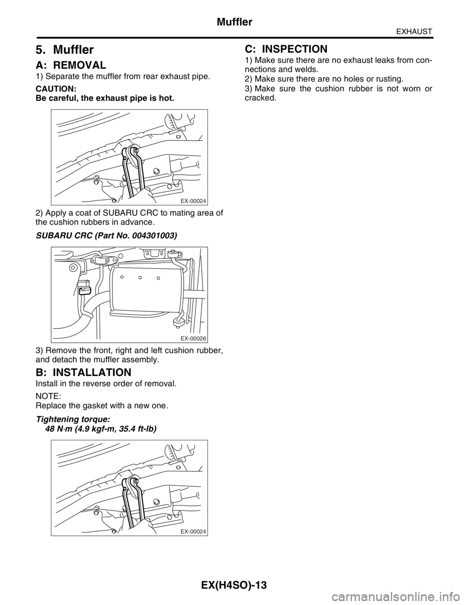
1) Separate the muffler from rear exhaust pipe.
CAUTION:
Be careful, the exhaust pipe is hot.
2) Apply a coat of SUBARU CRC to mating area of
the cushion rubbers in advance.
SUBARU CRC (Part No. 004301003)
3) Remove the front, right and left cushion rubber,
and detach the muffler assembly.
B: INSTALLATION
Install in the reverse order of removal.
NOTE:
Replace the gasket with a new one.
Tightening torque:
48 N
⋅m (4.9 kgf-m, 35.4 ft-lb)
C: INSPECTION
1) Make sure there are no exhaust leaks from con-
nections and welds.
2) Make sure there are no holes or rusting.
3) Make sure the cushion rubber is not worn or
cracked.
EX-00024
EX-00026
EX-00024
Page 982 of 2870

EX(H4SO)-14
EXHAUST
Muffler
Page 983 of 2870
FUJI HEAVY INDUSTRIES LTD. G8080GE2
2004 FORESTER SERVICE MANUAL QUICK REFERENCE INDEX
ENGINE SECTION 1
This service manual has been prepared
to provide SUBARU service personnel
with the necessary information and data
for the correct maintenance and repair
of SUBARU vehicles.
This manual includes the procedures
for maintenance, disassembling, reas-
sembling, inspection and adjustment of
components and diagnostics for guid-
ance of experienced mechanics.
Please peruse and utilize this manual
fully to ensure complete repair work for
satisfying our customers by keeping
their vehicle in optimum condition.
When replacement of parts during
repair work is needed, be sure to use
SUBARU genuine parts.
All information, illustration and specifi-
cations contained in this manual are
based on the latest product information
available at the time of publication
approval.FUEL INJECTION (FUEL SYSTEM) FU(H4SO)
EMISSION CONTROL
(AUX. EMISSION CONTROL DEVICE)EC(H4SO)
INTAKE (INDUCTION) IN(H4SO)
MECHANICAL ME(H4SO)
EXHAUST EX(H4SO)
COOLING CO(H4SO)
LUBRICATION LU(H4SO)
SPEED CONTROL SYSTEM SP(H4SO)
IGNITION IG(H4SO)
STARTING/CHARGING SYSTEM SC(H4SO)
ENGINE (DIAGNOSTIC) EN(H4SO)
Page 984 of 2870

COOLING
CO(H4SO)
Page
1. General Description ....................................................................................2
2. Radiator Fan System ................................................................................13
3. Engine Coolant..........................................................................................19
4. Water Pump ..............................................................................................21
5. Thermostat ................................................................................................26
6. Radiator.....................................................................................................28
7. Radiator Cap .............................................................................................34
8. Radiator Main Fan and Fan Motor ............................................................35
9. Radiator Sub Fan and Fan Motor..............................................................40
10. Reservoir Tank ..........................................................................................41
11. Coolant Filler Tank ....................................................................................42
12. Engine Cooling System Trouble in General ..............................................43
Page 985 of 2870

CO(H4SO)-2
COOLING
General Description
1. General Description
A: SPECIFICATION
ModelNon-turbo Turbo
Cooling system Electric fan+Forced engine coolant circulation system
Total engine coolant capacity2(US qt, Imp qt)2.0L with ATF warmer:
Approx. 6.9 (7.29, 6.07)
2.0L AT:
Approx. 6.5 (6.87, 5.72)
2.0L MT:
Approx. 6.6 (6.98, 5.81)
2.5L AT:
Approx. 6.8 (7.19, 5.98)
2.5L MT:
Approx. 6.9 (7.29, 6.07)AT :
Approx. 7.3 (7.71, 6.42)
MT with oil cooler:
Approx. 7.3 (7.71, 6.42)
MT without oil cooler:
Approx. 7.4 (7.82, 6.51)
Water pumpType Centrifugal impeller type
Discharge perfor-
mance IDischarge 202 (5.3 US gal, 4.4 Imp gal)/min.
Pump speed — Discharge
pressure760 rpm — 2.9 kPa (0.3 mAq)
Engine coolant temperature 85°C (185°F)
Discharge perfor-
mance IIDischarge 1002 (26.4 US gal, 22.0 Imp gal)/min.
Pump speed — Discharge
pressure3,000 rpm — 49.0 kPa (5.0 mAq)
Engine coolant temperature 85°C (185°F)
Discharge perfor-
mance IIIDischarge 2002 (52.8 US gal, 44.0 Imp gal)/min.
Pump speed — Discharge
pressure6,000 rpm — 225.4 kPa (23.0 mAq)
Engine coolant temperature 85°C (185°F)
Impeller diameter 76 mm (2.99 in)
Number of impeller vanes 8
Pump pulley diameter 60 mm (2.36 in)
Clearance between
impeller and caseStandard 0.5 — 0.7 mm (0.020 — 0.028 in)
Limit 1.0 mm (0.039 in)
“Thrust” runout of impeller end 0.5 mm (0.020 in)
ThermostatType Wax pellet type
Starts to open 80 — 84°C (176 — 183°F) 76 — 80°C (169 — 176°F)
Fully opened 95°C (203°F) 91°C (196°F)
Valve lift 9.0 mm (0.354 in) or more
Valve bore 35 mm (1.38 in)
Radiator fanMotorMain fan 70 W2.0L AT (K4
★1) : 70 W
2.0L AT (EC, EK★1) :
120 W
2.0 L MT: 70 W
2.5 L: 120 W
Sub fan 70 W2.0L AT (K4
★1) : 70 W
2.0L AT (EC, EK★1) :
120 W
2.0 L MT: 70 W
2.5 L: 120 W
Fan diameter×Blade320 mm (11.81 in)×5 (main fan)
320 mm (11.81 in)×7 (sub fan)
Page 986 of 2870

CO(H4SO)-3
COOLING
General Description
★1: For option code, refer to ID section.
Core dimensions Width×Height×Thickness691.5×360×16 mm
(27.22×14.17×0.63 in)
Pressure range in which cap valve is openAbove: 108±15 kPa
(1.1±0.15 kg/cm
2, 16±2 psi)
Below: −1.0 to −4.9 kPa
(−0.01 to −0.05 kg/cm
2, −0.1 to −0.7 psi)
Fins Corrugated fin type
Reservoir
tankCapacity 0.52 (0.5 US qt, 0.4 Imp qt)
Page 987 of 2870
CO(H4SO)-4
COOLING
General Description
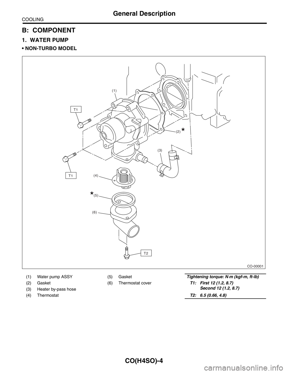
B: COMPONENT
1. WATER PUMP
NON-TURBO MODEL
(1) Water pump ASSY (5) GasketTightening torque: N⋅m (kgf-m, ft-lb)
(2) Gasket (6) Thermostat coverT1: First 12 (1.2, 8.7)
Second 12 (1.2, 8.7)
(3) Heater by-pass hose
(4) ThermostatT2: 6.5 (0.66, 4.8)
CO-00001
T2(2) (1)
(4)
T1
(3)
(5)
(6)
T1
Page 988 of 2870
CO(H4SO)-5
COOLING
General Description
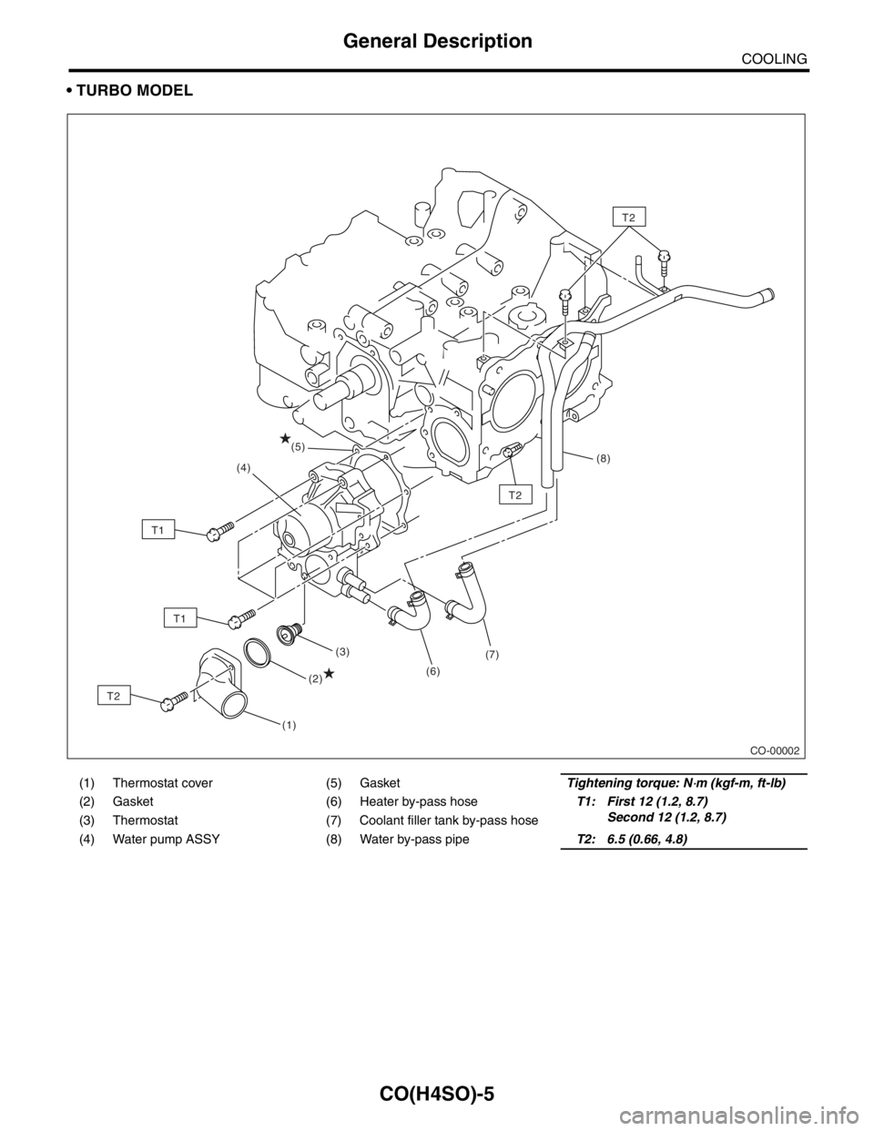
TURBO MODEL
(1) Thermostat cover (5) GasketTightening torque: N⋅m (kgf-m, ft-lb)
(2) Gasket (6) Heater by-pass hoseT1: First 12 (1.2, 8.7)
Second 12 (1.2, 8.7)
(3) Thermostat (7) Coolant filler tank by-pass hose
(4) Water pump ASSY (8) Water by-pass pipeT2: 6.5 (0.66, 4.8)
CO-00002
T2
(1)(3)
(6)(7)(8)
(4)
(2)
(5)
T2
T2
T1
T1
Page 989 of 2870
CO(H4SO)-6
COOLING
General Description
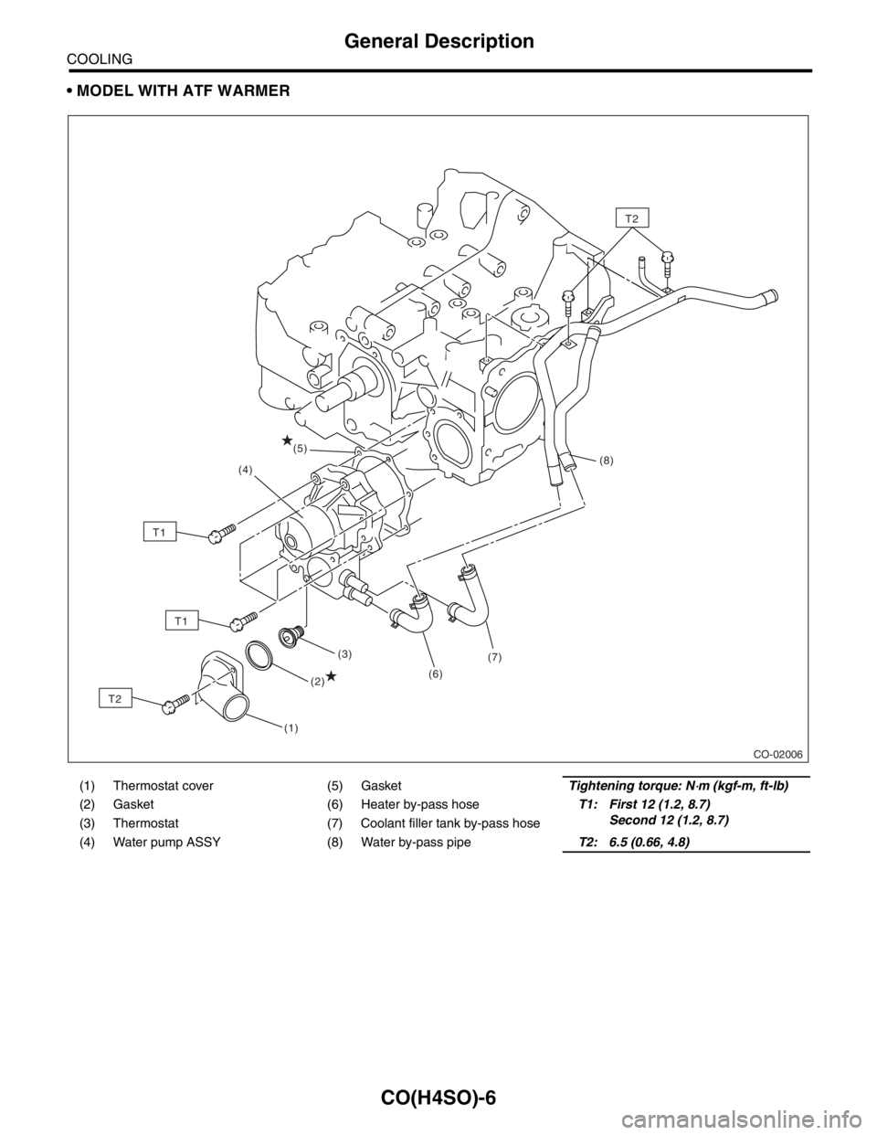
MODEL WITH ATF WARMER
(1) Thermostat cover (5) GasketTightening torque: N⋅m (kgf-m, ft-lb)
(2) Gasket (6) Heater by-pass hoseT1: First 12 (1.2, 8.7)
Second 12 (1.2, 8.7)
(3) Thermostat (7) Coolant filler tank by-pass hose
(4) Water pump ASSY (8) Water by-pass pipeT2: 6.5 (0.66, 4.8)
CO-02006
(1)(3)
(6)(7)(8)
(4)
(2)
(5)
T2
T2
T1
T1
Page 990 of 2870
CO(H4SO)-7
COOLING
General Description
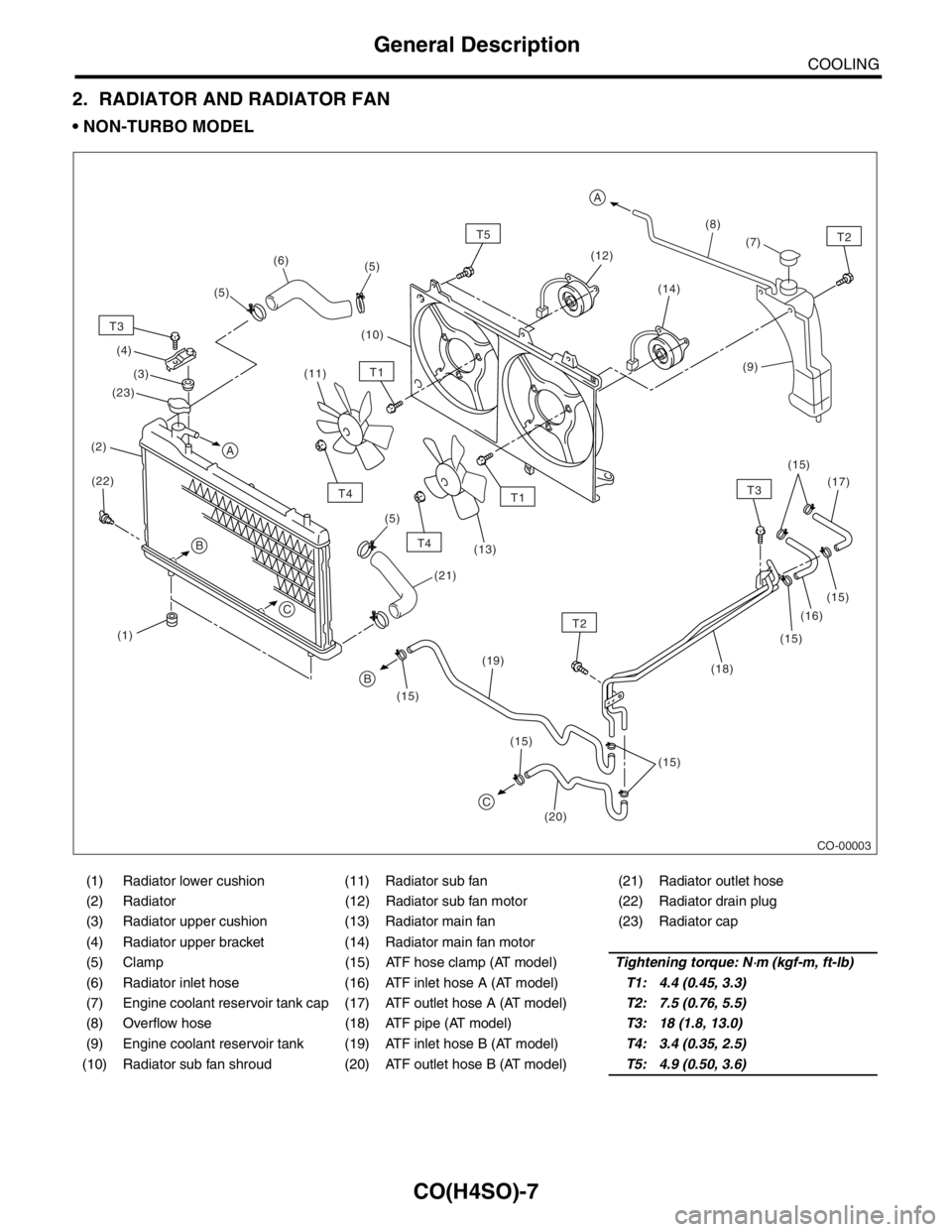
2. RADIATOR AND RADIATOR FAN
NON-TURBO MODEL
(1) Radiator lower cushion (11) Radiator sub fan (21) Radiator outlet hose
(2) Radiator (12) Radiator sub fan motor (22) Radiator drain plug
(3) Radiator upper cushion (13) Radiator main fan (23) Radiator cap
(4) Radiator upper bracket (14) Radiator main fan motor
(5) Clamp (15) ATF hose clamp (AT model)Tightening torque: N
⋅m (kgf-m, ft-lb)
(6) Radiator inlet hose (16) ATF inlet hose A (AT model)T1: 4.4 (0.45, 3.3)
(7) Engine coolant reservoir tank cap (17) ATF outlet hose A (AT model)T2: 7.5 (0.76, 5.5)
(8) Overflow hose (18) ATF pipe (AT model)T3: 18 (1.8, 13.0)
(9) Engine coolant reservoir tank (19) ATF inlet hose B (AT model)T4: 3.4 (0.35, 2.5)
(10) Radiator sub fan shroud (20) ATF outlet hose B (AT model)T5: 4.9 (0.50, 3.6)
CO-00003
(9)
(1)(10)(8)
(2)
T3
T2
T2
T4
T4(14)
(20) (22)(3) (4)
(19)(16)
(18)(7)
(17)
(15) (15)
(15)
(15) (15) (15)(12)
(11)
(13)
T5
T1
T1
(5) (5)
(5)(6)
(21)
A
A
C
T3
B
B
C
(23)