SUBARU FORESTER 2004 Service Repair Manual
Manufacturer: SUBARU, Model Year: 2004, Model line: FORESTER, Model: SUBARU FORESTER 2004Pages: 2870, PDF Size: 38.67 MB
Page 2791 of 2870
5MT-78
MANUAL TRANSMISSION AND DIFFERENTIAL
Main Shaft Assembly For Dual-Range
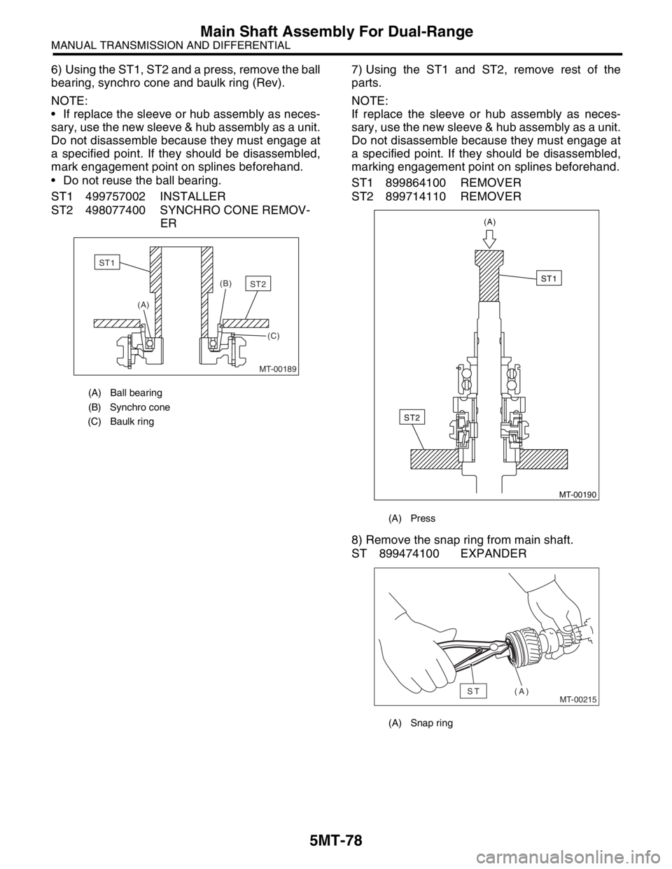
6) Using the ST1, ST2 and a press, remove the ball
bearing, synchro cone and baulk ring (Rev).
NOTE:
If replace the sleeve or hub assembly as neces-
sary, use the new sleeve & hub assembly as a unit.
Do not disassemble because they must engage at
a specified point. If they should be disassembled,
mark engagement point on splines beforehand.
Do not reuse the ball bearing.
ST1 499757002 INSTALLER
ST2 498077400 SYNCHRO CONE REMOV-
ER7) Using the ST1 and ST2, remove rest of the
parts.
NOTE:
If replace the sleeve or hub assembly as neces-
sary, use the new sleeve & hub assembly as a unit.
Do not disassemble because they must engage at
a specified point. If they should be disassembled,
marking engagement point on splines beforehand.
ST1 899864100 REMOVER
ST2 899714110 REMOVER
8) Remove the snap ring from main shaft.
ST 899474100 EXPANDER
(A) Ball bearing
(B) Synchro cone
(C) Baulk ring
MT-00189
(B)
(A)
(C)ST2
ST1
(A) Press
(A) Snap ring
MT-00190
(A)
ST2
ST1
MT-00215(A)ST
Page 2792 of 2870
5MT-79
MANUAL TRANSMISSION AND DIFFERENTIAL
Main Shaft Assembly For Dual-Range
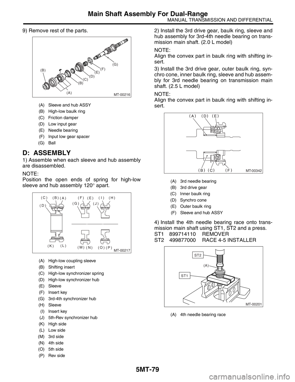
9) Remove rest of the parts.
D: ASSEMBLY
1) Assemble when each sleeve and hub assembly
are disassembled.
NOTE:
Position the open ends of spring for high-low
sleeve and hub assembly 120° apart.2) Install the 3rd drive gear, baulk ring, sleeve and
hub assembly for 3rd-4th needle bearing on trans-
mission main shaft. (2.0 L model)
NOTE:
Align the convex part in baulk ring with shifting in-
sert.
3) Install the 3rd drive gear, outer baulk ring, syn-
chro cone, inner baulk ring, sleeve and hub assem-
bly for 3rd needle bearing on transmission main
shaft. (2.5 L model)
NOTE:
Align the convex part in baulk ring with shifting in-
sert.
4) Install the 4th needle bearing race onto trans-
mission main shaft using ST1, ST2 and a press.
ST1 899714110 REMOVER
ST2 499877000 RACE 4-5 INSTALLER
(A) Sleeve and hub ASSY
(B) High-low baulk ring
(C) Friction damper
(D) Low input gear
(E) Needle bearing
(F) Input low gear spacer
(G) Ball
(A) High-low coupling sleeve
(B) Shifting insert
(C) High-low synchronizer spring
(D) High-low synchronizer hub
(E) Sleeve
(F) Insert key
(G) 3rd-4th synchronizer hub
(H) Sleeve
(I) Insert key
(J) 5th-Rev synchronizer hub
(K) High side
(L) Low side
(M) 3rd side
(N) 4th side
(O) 5th side
(P) Rev side
MT-00216
(B)
(A)(E)(F)(G)
(D)
(C)
(B)
MT-00217
(B)
(A)
(D)(G)(F)
(E)(I) (H)
(J)
(K)(L)
(M)
(N) (O)
(P) (C)
(A) 3rd needle bearing
(B) 3rd drive gear
(C) Inner baulk ring
(D) Synchro cone
(E) Outer baulk ring
(F) Sleeve and hub ASSY
(A) 4th needle bearing race
MT-00342
MT-00201
(A)
ST1
ST2
Page 2793 of 2870
5MT-80
MANUAL TRANSMISSION AND DIFFERENTIAL
Main Shaft Assembly For Dual-Range
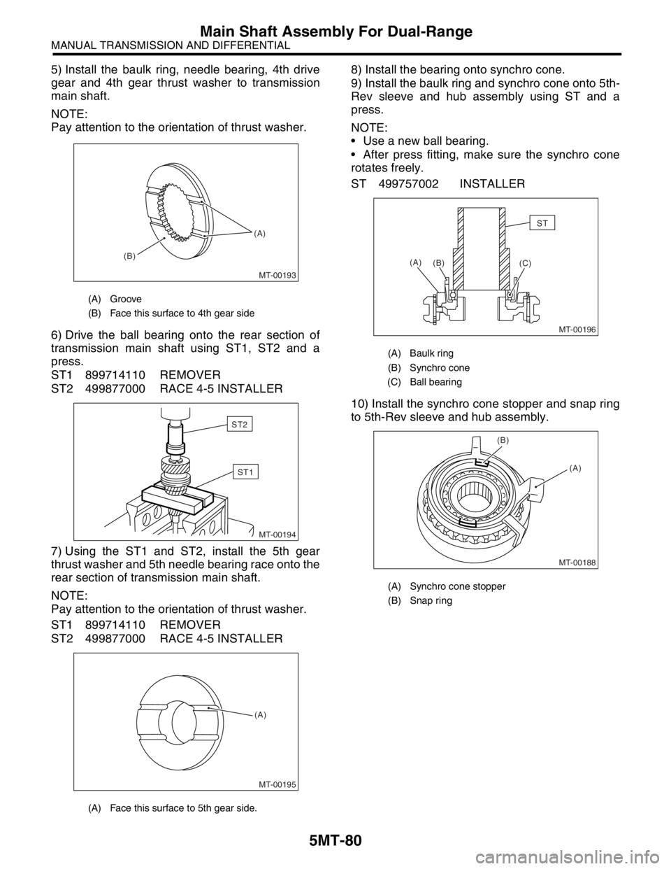
5) Install the baulk ring, needle bearing, 4th drive
gear and 4th gear thrust washer to transmission
main shaft.
NOTE:
Pay attention to the orientation of thrust washer.
6) Drive the ball bearing onto the rear section of
transmission main shaft using ST1, ST2 and a
press.
ST1 899714110 REMOVER
ST2 499877000 RACE 4-5 INSTALLER
7) Using the ST1 and ST2, install the 5th gear
thrust washer and 5th needle bearing race onto the
rear section of transmission main shaft.
NOTE:
Pay attention to the orientation of thrust washer.
ST1 899714110 REMOVER
ST2 499877000 RACE 4-5 INSTALLER8) Install the bearing onto synchro cone.
9) Install the baulk ring and synchro cone onto 5th-
Rev sleeve and hub assembly using ST and a
press.
NOTE:
Use a new ball bearing.
After press fitting, make sure the synchro cone
rotates freely.
ST 499757002 INSTALLER
10) Install the synchro cone stopper and snap ring
to 5th-Rev sleeve and hub assembly.
(A) Groove
(B) Face this surface to 4th gear side
(A) Face this surface to 5th gear side.
MT-00193 (A)
(B)
MT-00194
ST1
ST2
MT-00195
(A)
(A) Baulk ring
(B) Synchro cone
(C) Ball bearing
(A) Synchro cone stopper
(B) Snap ring
MT-00196
(B) (A)
(C)
ST
MT-00188
(A) (B)
Page 2794 of 2870
5MT-81
MANUAL TRANSMISSION AND DIFFERENTIAL
Main Shaft Assembly For Dual-Range
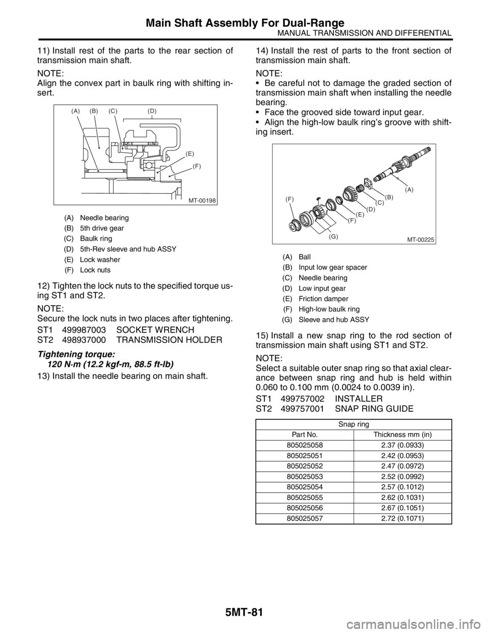
11) Install rest of the parts to the rear section of
transmission main shaft.
NOTE:
Align the convex part in baulk ring with shifting in-
sert.
12) Tighten the lock nuts to the specified torque us-
ing ST1 and ST2.
NOTE:
Secure the lock nuts in two places after tightening.
ST1 499987003 SOCKET WRENCH
ST2 498937000 TRANSMISSION HOLDER
Tightening torque:
120 N·m (12.2 kgf-m, 88.5 ft-lb)
13) Install the needle bearing on main shaft.14) Install the rest of parts to the front section of
transmission main shaft.
NOTE:
Be careful not to damage the graded section of
transmission main shaft when installing the needle
bearing.
Face the grooved side toward input gear.
Align the high-low baulk ring’s groove with shift-
ing insert.
15) Install a new snap ring to the rod section of
transmission main shaft using ST1 and ST2.
NOTE:
Select a suitable outer snap ring so that axial clear-
ance between snap ring and hub is held within
0.060 to 0.100 mm (0.0024 to 0.0039 in).
ST1 499757002 INSTALLER
ST2 499757001 SNAP RING GUIDE
(A) Needle bearing
(B) 5th drive gear
(C) Baulk ring
(D) 5th-Rev sleeve and hub ASSY
(E) Lock washer
(F) Lock nuts
MT-00198
(A) (B) (C) (D)
(E)
(F)
(A) Ball
(B) Input low gear spacer
(C) Needle bearing
(D) Low input gear
(E) Friction damper
(F) High-low baulk ring
(G) Sleeve and hub ASSY
Snap ring
Part No. Thickness mm (in)
805025058 2.37 (0.0933)
805025051 2.42 (0.0953)
805025052 2.47 (0.0972)
805025053 2.52 (0.0992)
805025054 2.57 (0.1012)
805025055 2.62 (0.1031)
805025056 2.67 (0.1051)
805025057 2.72 (0.1071)
MT-00225
(F)
(G)(C)(B)(A)
(D)
(E)
(F)
Page 2795 of 2870

5MT-82
MANUAL TRANSMISSION AND DIFFERENTIAL
Main Shaft Assembly For Dual-Range
E: INSPECTION
Disassembled parts should be washed clean first
and then inspected carefully.
1) Bearings
Replace the bearings in the following cases:
Bearings whose balls, outer races and inner rac-
es are broken or rusty.
Worn bearings
Bearings that fail to turn smoothly or make noise
when turned after gear oil lubrication.
Bearings having other defects
2) Bushing (each gear)
Replace the bushing in the following cases:
When the sliding surface is damaged or abnor-
mally worn.
When the inner wall is abnormally worn.
3) Gears
Replace the gears with new ones if their tooth
surfaces are broken, damaged, or excessively
worn.
Correct or replace if the cone that contacts the
baulk ring is rough or damaged.
Correct or replace if the inner surface or end face
is damaged.
4) Baulk ring
Replace the ring in the following cases:
When the inner surface and end face are dam-
aged.
When the ring inner surface is abnormally or par-
tially worn down.
When the contact surface of the synchronizer
ring insert is scored or abnormally worn down.
5) Shifting insert key
Replace the insert if deformed, excessively worn,
or defective in any way.
6) Oil seal
Replace the oil seal if the lip is deformed, hard-
ened, damaged, worn, or defective in any way.
7) O-ring
Replace the O-ring if the sealing face is deformed,
hardened, damaged, worn, or defective in any way.
8) Gearshift mechanism
Repair or replace the gearshift mechanism if ex-
cessively worn, bent, or defective in any way.
F: ADJUSTMENT
Choose the main shaft rear plate.
Range.>
Page 2796 of 2870
5MT-83
MANUAL TRANSMISSION AND DIFFERENTIAL
Input Shaft Assembly
19.Input Shaft Assembly
A: REMOVAL
1) Remove the manual transmission assembly
from vehicle.
2) Remove the transfer case with extension case
assembly.
3) Remove the transmission case.
4) Remove the drive pinion shaft assembly.
bly.>
5) Remove the main shaft assembly and input shaft
assembly.
B: INSTALLATION
1) Install the needle bearing onto the front of trans-
mission main shaft assembly.
2) Connect the main shaft assembly and input shaft
assembly.
3) Install the needle bearing outer race knock pin
hole into transmission case knock pin.
4) Install the drive pinion assembly.
bly.>
5) Install the transmission case.
6) Install the transfer case with extension case as-
sembly.
7) Install the manual transmission assembly on ve-
hicle.
C: DISASSEMBLY
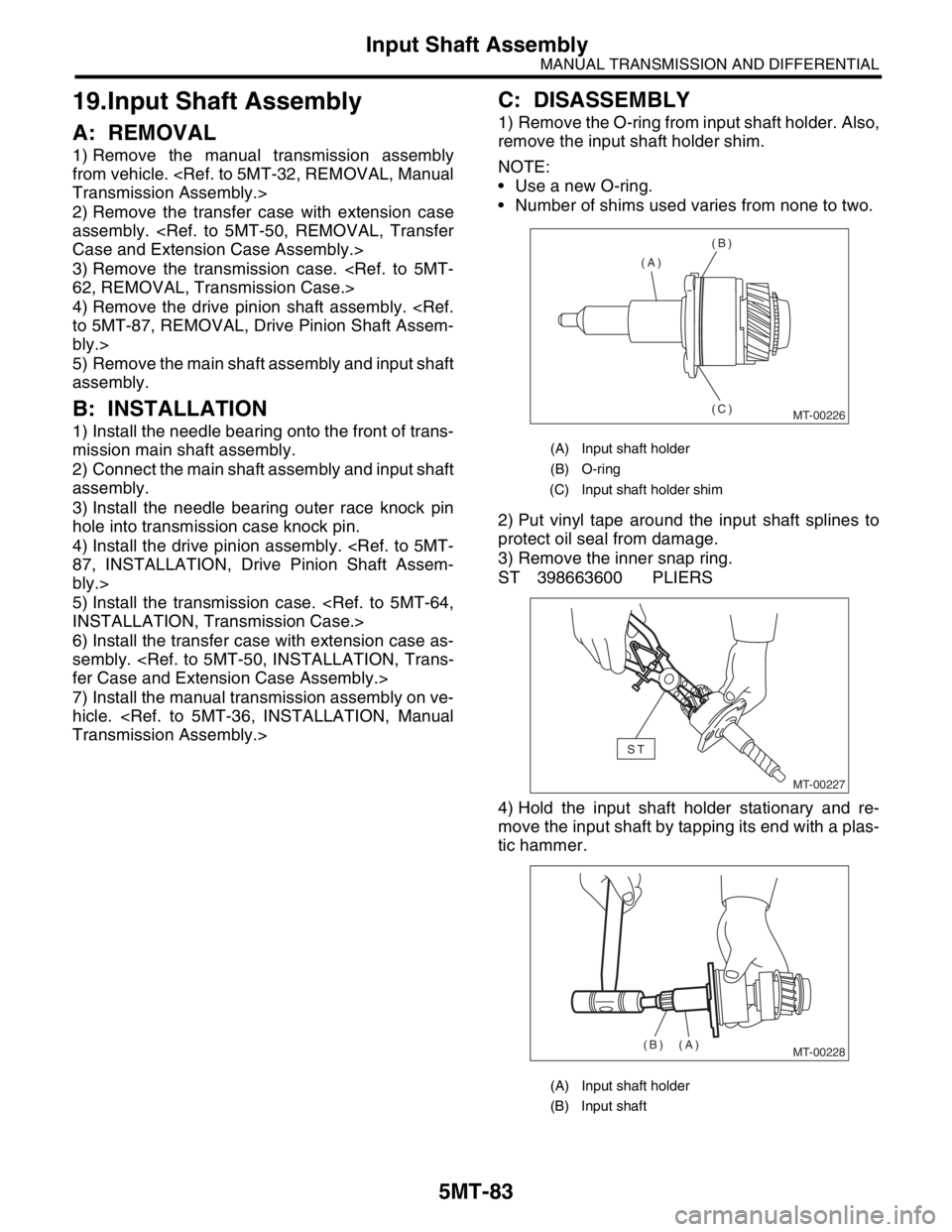
1) Remove the O-ring from input shaft holder. Also,
remove the input shaft holder shim.
NOTE:
Use a new O-ring.
Number of shims used varies from none to two.
2) Put vinyl tape around the input shaft splines to
protect oil seal from damage.
3) Remove the inner snap ring.
ST 398663600 PLIERS
4) Hold the input shaft holder stationary and re-
move the input shaft by tapping its end with a plas-
tic hammer.
(A) Input shaft holder
(B) O-ring
(C) Input shaft holder shim
(A) Input shaft holder
(B) Input shaft
MT-00226
(A)(B)
(C)
MT-00227
ST
MT-00228(A)
(B)
Page 2797 of 2870
5MT-84
MANUAL TRANSMISSION AND DIFFERENTIAL
Input Shaft Assembly
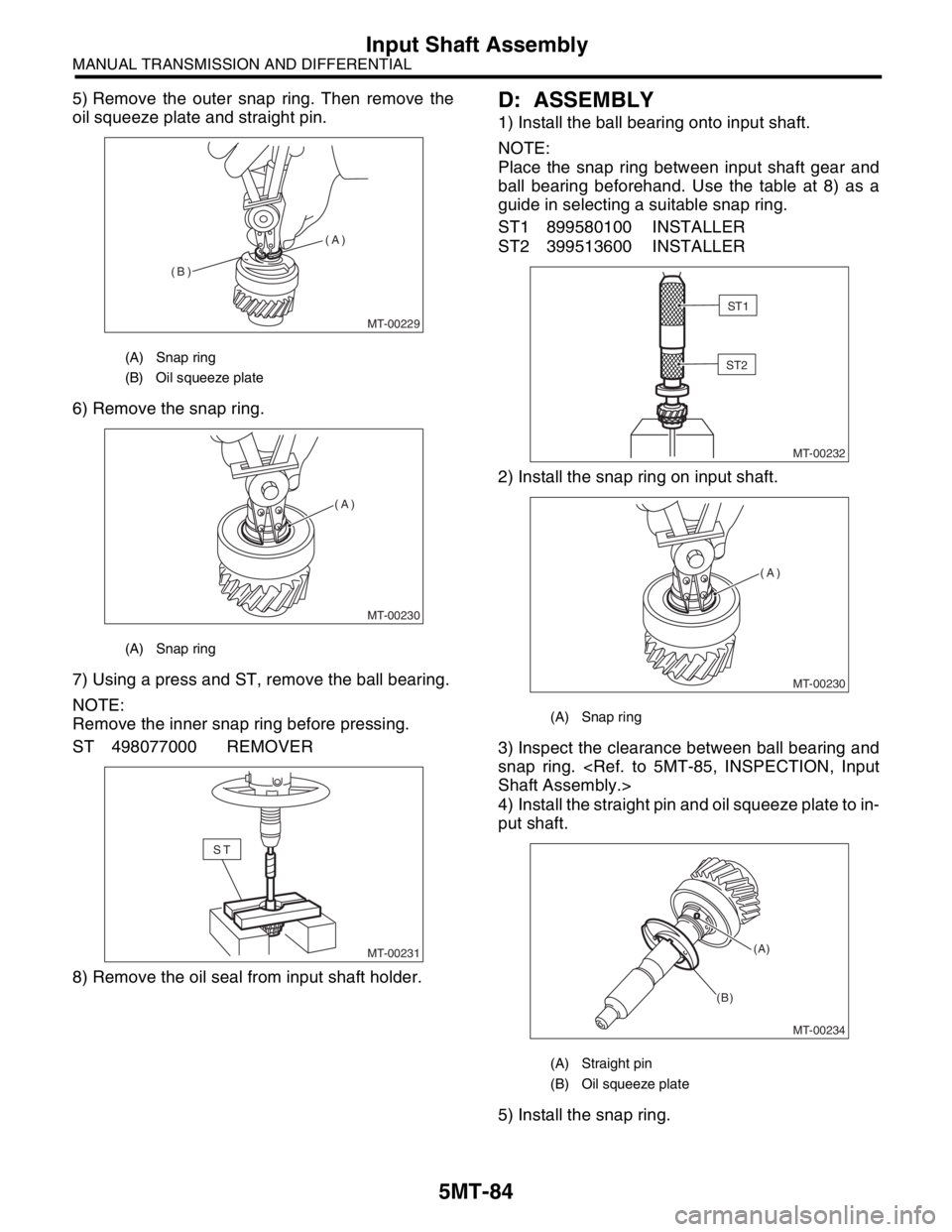
5) Remove the outer snap ring. Then remove the
oil squeeze plate and straight pin.
6) Remove the snap ring.
7) Using a press and ST, remove the ball bearing.
NOTE:
Remove the inner snap ring before pressing.
ST 498077000 REMOVER
8) Remove the oil seal from input shaft holder.D: ASSEMBLY
1) Install the ball bearing onto input shaft.
NOTE:
Place the snap ring between input shaft gear and
ball bearing beforehand. Use the table at 8) as a
guide in selecting a suitable snap ring.
ST1 899580100 INSTALLER
ST2 399513600 INSTALLER
2) Install the snap ring on input shaft.
3) Inspect the clearance between ball bearing and
snap ring.
4) Install the straight pin and oil squeeze plate to in-
put shaft.
5) Install the snap ring.
(A) Snap ring
(B) Oil squeeze plate
(A) Snap ring
MT-00229
(A)
(B)
MT-00230
(A)
MT-00231
ST
(A) Snap ring
(A) Straight pin
(B) Oil squeeze plate
MT-00232
ST1
ST2
MT-00230
(A)
MT-00234
(A)
(B)
Page 2798 of 2870
5MT-85
MANUAL TRANSMISSION AND DIFFERENTIAL
Input Shaft Assembly
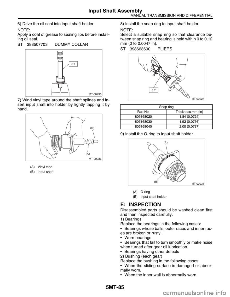
6) Drive the oil seal into input shaft holder.
NOTE:
Apply a coat of grease to sealing lips before install-
ing oil seal.
ST 398507703 DUMMY COLLAR
7) Wind vinyl tape around the shaft splines and in-
sert input shaft into holder by lightly tapping it by
hand.8) Install the snap ring to input shaft holder.
NOTE:
Select a suitable snap ring so that clearance be-
tween snap ring and bearing is held within 0 to 0.12
mm (0 to 0.0047 in).
ST 398663600 PLIERS
9) Install the O-ring to input shaft holder.
E: INSPECTION
Disassembled parts should be washed clean first
and then inspected carefully.
1) Bearings
Replace the bearings in the following cases:
Bearings whose balls, outer races and inner rac-
es are broken or rusty.
Worn bearings
Bearings that fail to turn smoothly or make noise
when turned after gear oil lubrication.
Bearings having other defects
2) Bushing (each gear)
Replace the bushing in the following cases:
When the sliding surface is damaged or abnor-
mally worn.
When the inner wall is abnormally worn.
(A) Vinyl tape
(B) Input shaft
MT-00235
ST
MT-00236
(A)(B)
Snap ring
Part No. Thickness mm (in)
805168020 1.84 (0.0724)
805168030 1.92 (0.0756)
805168040 2.00 (0.0787)
(A) O-ring
(B) Input shaft holder
MT-00227
ST
MT-00238
(A)
(B)
Page 2799 of 2870
5MT-86
MANUAL TRANSMISSION AND DIFFERENTIAL
Input Shaft Assembly
3) Gears
Replace the gears with new ones if their tooth
surfaces are broken, damaged, or excessively
worn.
Correct or replace if the cone that contacts the
baulk ring is rough or damaged.
Correct or replace if the inner surface or end face
is damaged.
4) Baulk ring
Replace the ring in the following cases:
When the inner surface and end face are dam-
aged.
When the ring inner surface is excessively or
partially worn down.
When the contact surface of the synchronizer
ring insert is scored or abnormally worn down.
5) Shifting insert key
Replace the insert if deformed, excessively worn,
or defective in any way.
6) Oil seal
Replace the oil seal if the lip is deformed, hard-
ened, damaged, worn, or defective in any way.
7) O-ring
Replace the O-ring if the sealing face is deformed,
hardened, damaged, worn, or defective in any way.
8) Gearshift mechanism
Repair or replace the gearshift mechanism if ex-
cessively worn, bent, or defective in any way.
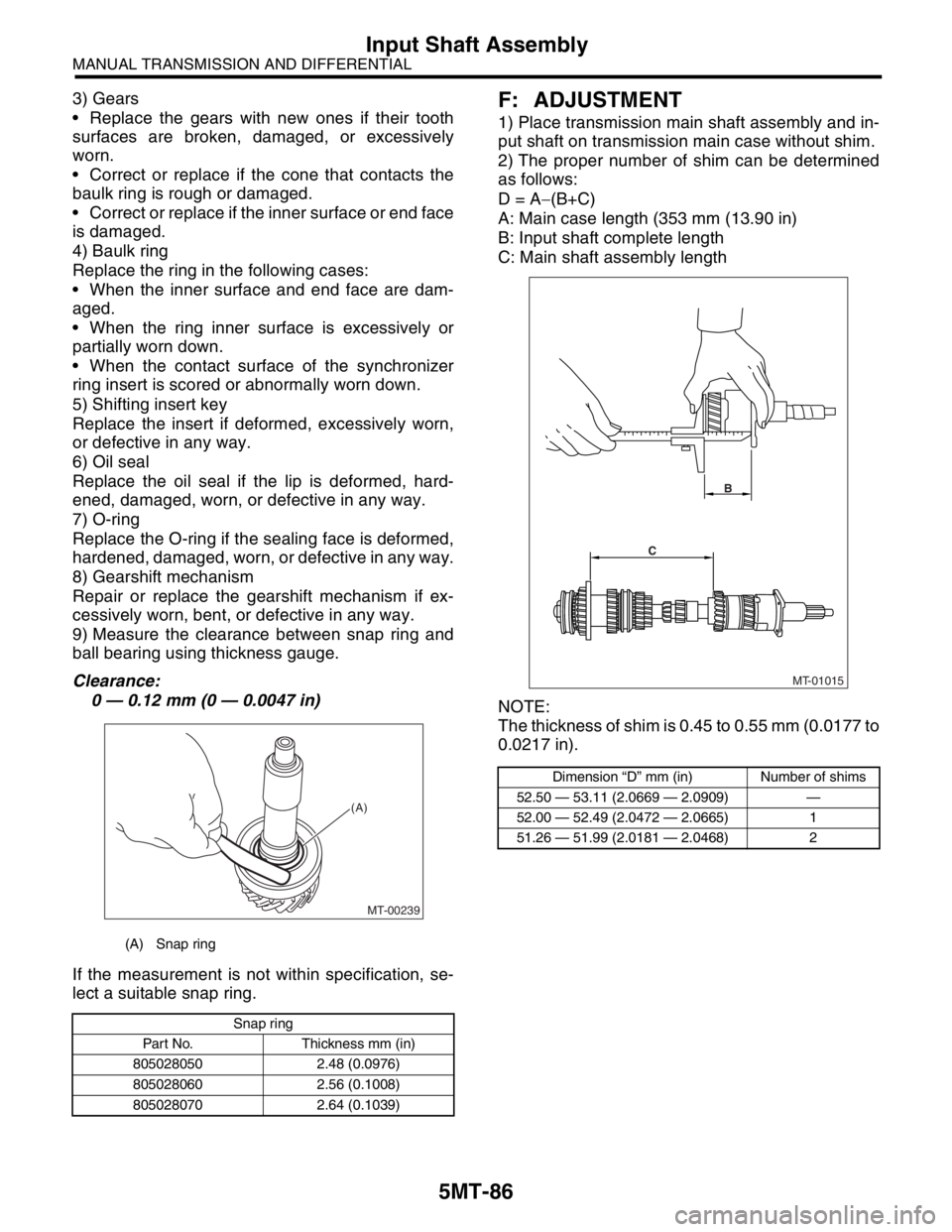
9) Measure the clearance between snap ring and
ball bearing using thickness gauge.
Clearance:
0 — 0.12 mm (0 — 0.0047 in)
If the measurement is not within specification, se-
lect a suitable snap ring.F: ADJUSTMENT
1) Place transmission main shaft assembly and in-
put shaft on transmission main case without shim.
2) The proper number of shim can be determined
as follows:
D = A−(B+C)
A: Main case length (353 mm (13.90 in)
B: Input shaft complete length
C: Main shaft assembly length
NOTE:
The thickness of shim is 0.45 to 0.55 mm (0.0177 to
0.0217 in).
(A) Snap ring
Snap ring
Part No. Thickness mm (in)
805028050 2.48 (0.0976)
805028060 2.56 (0.1008)
805028070 2.64 (0.1039)
MT-00239
(A)
Dimension “D” mm (in) Number of shims
52.50 — 53.11 (2.0669 — 2.0909) —
52.00 — 52.49 (2.0472 — 2.0665) 1
51.26 — 51.99 (2.0181 — 2.0468) 2
MT-01015
CB
Page 2800 of 2870
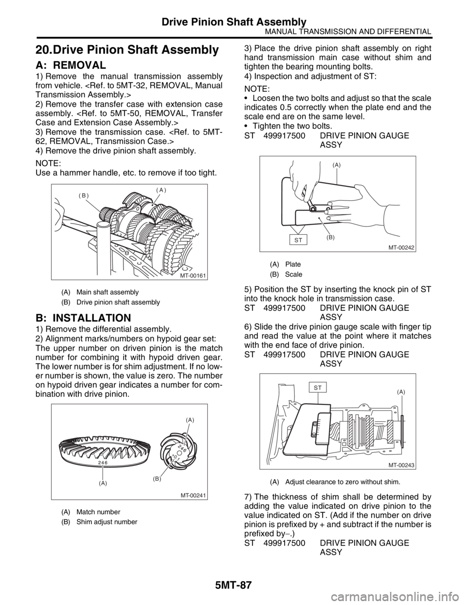
5MT-87
MANUAL TRANSMISSION AND DIFFERENTIAL
Drive Pinion Shaft Assembly
20.Drive Pinion Shaft Assembly
A: REMOVAL
1) Remove the manual transmission assembly
from vehicle.
2) Remove the transfer case with extension case
assembly.
3) Remove the transmission case.
4) Remove the drive pinion shaft assembly.
NOTE:
Use a hammer handle, etc. to remove if too tight.
B: INSTALLATION
1) Remove the differential assembly.
2) Alignment marks/numbers on hypoid gear set:
The upper number on driven pinion is the match
number for combining it with hypoid driven gear.
The lower number is for shim adjustment. If no low-
er number is shown, the value is zero. The number
on hypoid driven gear indicates a number for com-
bination with drive pinion.3) Place the drive pinion shaft assembly on right
hand transmission main case without shim and
tighten the bearing mounting bolts.
4) Inspection and adjustment of ST:
NOTE:
Loosen the two bolts and adjust so that the scale
indicates 0.5 correctly when the plate end and the
scale end are on the same level.
Tighten the two bolts.
ST 499917500 DRIVE PINION GAUGE
ASSY
5) Position the ST by inserting the knock pin of ST
into the knock hole in transmission case.
ST 499917500 DRIVE PINION GAUGE
ASSY
6) Slide the drive pinion gauge scale with finger tip
and read the value at the point where it matches
with the end face of drive pinion.
ST 499917500 DRIVE PINION GAUGE
ASSY
7) The thickness of shim shall be determined by
adding the value indicated on drive pinion to the
value indicated on ST. (Add if the number on drive
pinion is prefixed by + and subtract if the number is
prefixed by−.)
ST 499917500 DRIVE PINION GAUGE
ASSY
(A) Main shaft assembly
(B) Drive pinion shaft assembly
(A) Match number
(B) Shim adjust number
MT-00161
(A)
(B)
MT-00241
(A)
(B)
(A)
+0.1
(A) Plate
(B) Scale
(A) Adjust clearance to zero without shim.
MT-00242
(A)
(B)
ST
MT-00243
(A)ST