SUBARU FORESTER 2004 Service Repair Manual
Manufacturer: SUBARU, Model Year: 2004, Model line: FORESTER, Model: SUBARU FORESTER 2004Pages: 2870, PDF Size: 38.67 MB
Page 761 of 2870
PM-24
PERIODIC MAINTENANCE SERVICE
Transmission Gear Oil
14.Transmission Gear Oil
A: REPLACEMENT
1. MANUAL TRANSMISSION
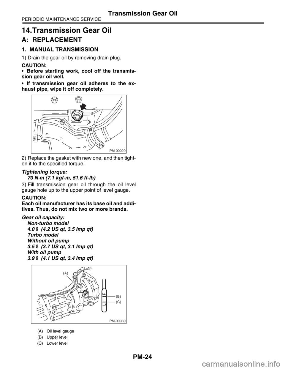
1) Drain the gear oil by removing drain plug.
CAUTION:
Before starting work, cool off the transmis-
sion gear oil well.
If transmission gear oil adheres to the ex-
haust pipe, wipe it off completely.
2) Replace the gasket with new one, and then tight-
en it to the specified torque.
Tightening torque:
70 N·m (7.1 kgf-m, 51.6 ft-lb)
3) Fill transmission gear oil through the oil level
gauge hole up to the upper point of level gauge.
CAUTION:
Each oil manufacturer has its base oil and addi-
tives. Thus, do not mix two or more brands.
Gear oil capacity:
Non-turbo model
4.02 (4.2 US qt, 3.5 Imp qt)
Turbo model
Without oil pump
3.52 (3.7 US qt, 3.1 Imp qt)
With oil pump
3.92 (4.1 US qt, 3.4 Imp qt)
(A) Oil level gauge
(B) Upper level
(C) Lower level
PM-00029
PM-00030
(B)
(C) (A)
Page 762 of 2870
PM-25
PERIODIC MAINTENANCE SERVICE
Hill-holder System
15.Hill-holder System
A: INSPECTION AND ADJUSTMENT
1) Confirm the stopping and starting performance
by activating the hill-holder on an uphill road of 3°
or higher inclination.
(1) When the vehicle does not stop;
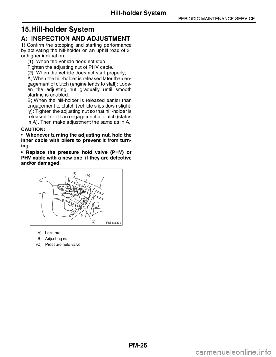
Tighten the adjusting nut of PHV cable.
(2) When the vehicle does not start properly;
A; When the hill-holder is released later than en-
gagement of clutch (engine tends to stall): Loos-
en the adjusting nut gradually until smooth
starting is enabled.
B; When the hill-holder is released earlier than
engagement to clutch (vehicle slips down slight-
ly): Tighten the adjusting nut so that hill-holder is
released later than engagement of clutch (status
in A). Then make adjustment the same as in A.
CAUTION:
Whenever turning the adjusting nut, hold the
inner cable with pliers to prevent it from turn-
ing.
Replace the pressure hold valve (PHV) or
PHV cable with a new one, if they are defective
and/or damaged.
(A) Lock nut
(B) Adjusting nut
(C) Pressure hold valve
(C) (B)
(A)
PM-00077
Page 763 of 2870
PM-26
PERIODIC MAINTENANCE SERVICE
ATF
16.ATF
A: INSPECTION
CAUTION:
The level of ATF varies with fluid temperature.
Pay attention to the fluid temperature when
checking ATF level.
1) Raise the ATF temperature by driving a distance
of 5 to 10 km (3 to 6 miles). Otherwise, idle the en-
gine to raise ATF temperature to 70 — 80°C (158
— 176°F) on Subaru Select Monitor.
TION, Subaru Select Monitor.>
2) Make sure the vehicle is level.
3) After selecting all positions (P, R, N, D, 3, 2, 1),
set the select lever in “P” range. Measure the ATF
level with the engine idling for one or two minutes.
4) Make sure that ATF level is above the center of
upper and lower level.
NOTE:
When the transmission is hot, the level should be
above the center of upper and lower marks, and
when it is cold, the level should be found below the
center of these two marks.
5) If the ATF level is below the center between up-
per and lower marks, add the recommended ATF
until the ATF level is found above the center be-
tween upper and lower marks.
CAUTION:
Use care not to exceed the upper limit level.
Remember that the addition of ATF to the up-
per limit mark when the transmission is cold
will result in overfilling of ATF, causing a trans-
mission failure.
6) Check ATF level after raising ATF temperature
to 70 — 80°C (158 — 176°F) by running the vehicle
or by idling the engine again.7) Check the ATF for leaks.
Check for leaks in the transmission. If there are
leaks, it is necessary to repair or replace gasket, oil
seals, plugs or other parts.
B: REPLACEMENT
1. AUTOMATIC TRANSMISSION FLUID
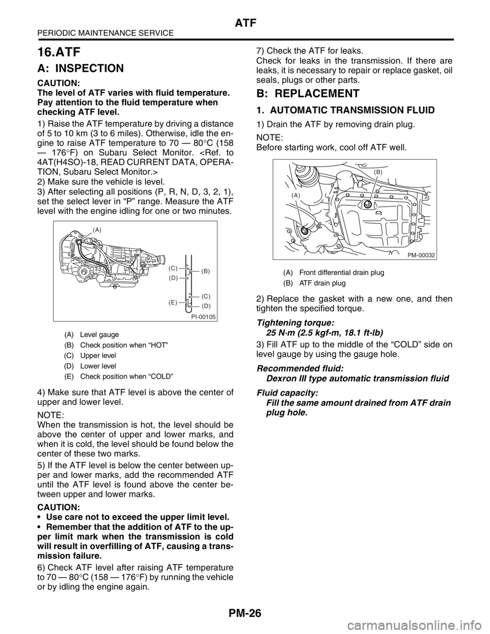
1) Drain the ATF by removing drain plug.
NOTE:
Before starting work, cool off ATF well.
2) Replace the gasket with a new one, and then
tighten the specified torque.
Tightening torque:
25 N·m (2.5 kgf-m, 18.1 ft-lb)
3) Fill ATF up to the middle of the “COLD” side on
level gauge by using the gauge hole.
Recommended fluid:
Dexron III type automatic transmission fluid
Fluid capacity:
Fill the same amount drained from ATF drain
plug hole.
(A) Level gauge
(B) Check position when “HOT”
(C) Upper level
(D) Lower level
(E) Check position when “COLD”
PI-00105
COLD
LFHOT LF
(A)
(C)
(D)
(C)
(D)
(E)
(B)(A) Front differential drain plug
(B) ATF drain plug
PM-00032
(B)
(A)
Page 764 of 2870
PM-27
PERIODIC MAINTENANCE SERVICE
ATF
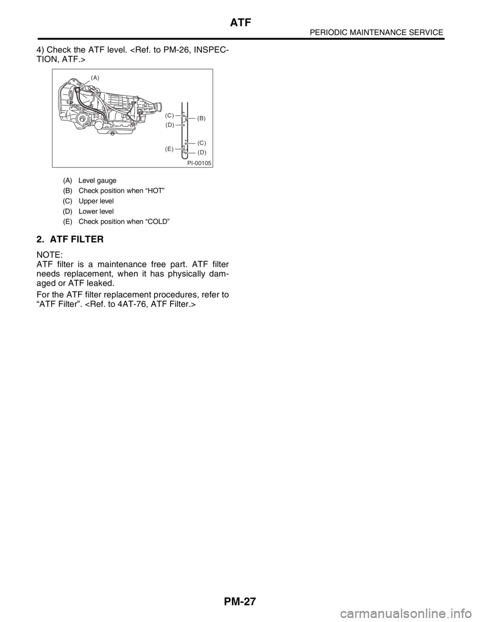
4) Check the ATF level.
2. ATF FILTER
NOTE:
ATF filter is a maintenance free part. ATF filter
needs replacement, when it has physically dam-
aged or ATF leaked.
For the ATF filter replacement procedures, refer to
“ATF Filter”.
(A) Level gauge
(B) Check position when “HOT”
(C) Upper level
(D) Lower level
(E) Check position when “COLD”
PI-00105
COLD
LFHOT LF
(A)
(C)
(D)
(C)
(D)
(E)
(B)
Page 765 of 2870
PM-28
PERIODIC MAINTENANCE SERVICE
Front & Rear Differential Oil
17.Front & Rear Differential Oil
A: REPLACEMENT
1. FRONT DIFFERENTIAL (MT MODEL)
For MT model, manual transmission oil works as
differential oil to lubricate differential. Refer to
“Transmission Oil”.
2. FRONT DIFFERENTIAL (AT MODEL)
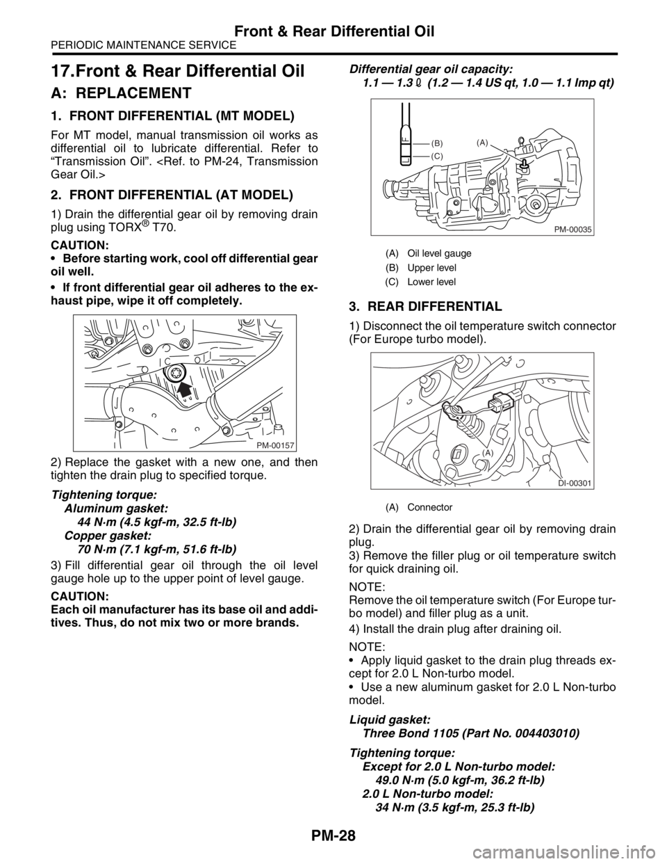
1) Drain the differential gear oil by removing drain
plug using TORX® T70.
CAUTION:
Before starting work, cool off differential gear
oil well.
If front differential gear oil adheres to the ex-
haust pipe, wipe it off completely.
2) Replace the gasket with a new one, and then
tighten the drain plug to specified torque.
Tightening torque:
Aluminum gasket:
44 N·m (4.5 kgf-m, 32.5 ft-lb)
Copper gasket:
70 N·m (7.1 kgf-m, 51.6 ft-lb)
3) Fill differential gear oil through the oil level
gauge hole up to the upper point of level gauge.
CAUTION:
Each oil manufacturer has its base oil and addi-
tives. Thus, do not mix two or more brands.Differential gear oil capacity:
1.1 — 1.32 (1.2 — 1.4 US qt, 1.0 — 1.1 Imp qt)
3. REAR DIFFERENTIAL
1) Disconnect the oil temperature switch connector
(For Europe turbo model).
2) Drain the differential gear oil by removing drain
plug.
3) Remove the filler plug or oil temperature switch
for quick draining oil.
NOTE:
Remove the oil temperature switch (For Europe tur-
bo model) and filler plug as a unit.
4) Install the drain plug after draining oil.
NOTE:
Apply liquid gasket to the drain plug threads ex-
cept for 2.0 L Non-turbo model.
Use a new aluminum gasket for 2.0 L Non-turbo
model.
Liquid gasket:
Three Bond 1105 (Part No. 004403010)
Tightening torque:
Except for 2.0 L Non-turbo model:
49.0 N·m (5.0 kgf-m, 36.2 ft-lb)
2.0 L Non-turbo model:
34 N·m (3.5 kgf-m, 25.3 ft-lb)
PM-00157
(A) Oil level gauge
(B) Upper level
(C) Lower level
(A) Connector
PM-00035
(B)
(C)(A)
DI-00301
(A)
Page 766 of 2870
PM-29
PERIODIC MAINTENANCE SERVICE
Front & Rear Differential Oil
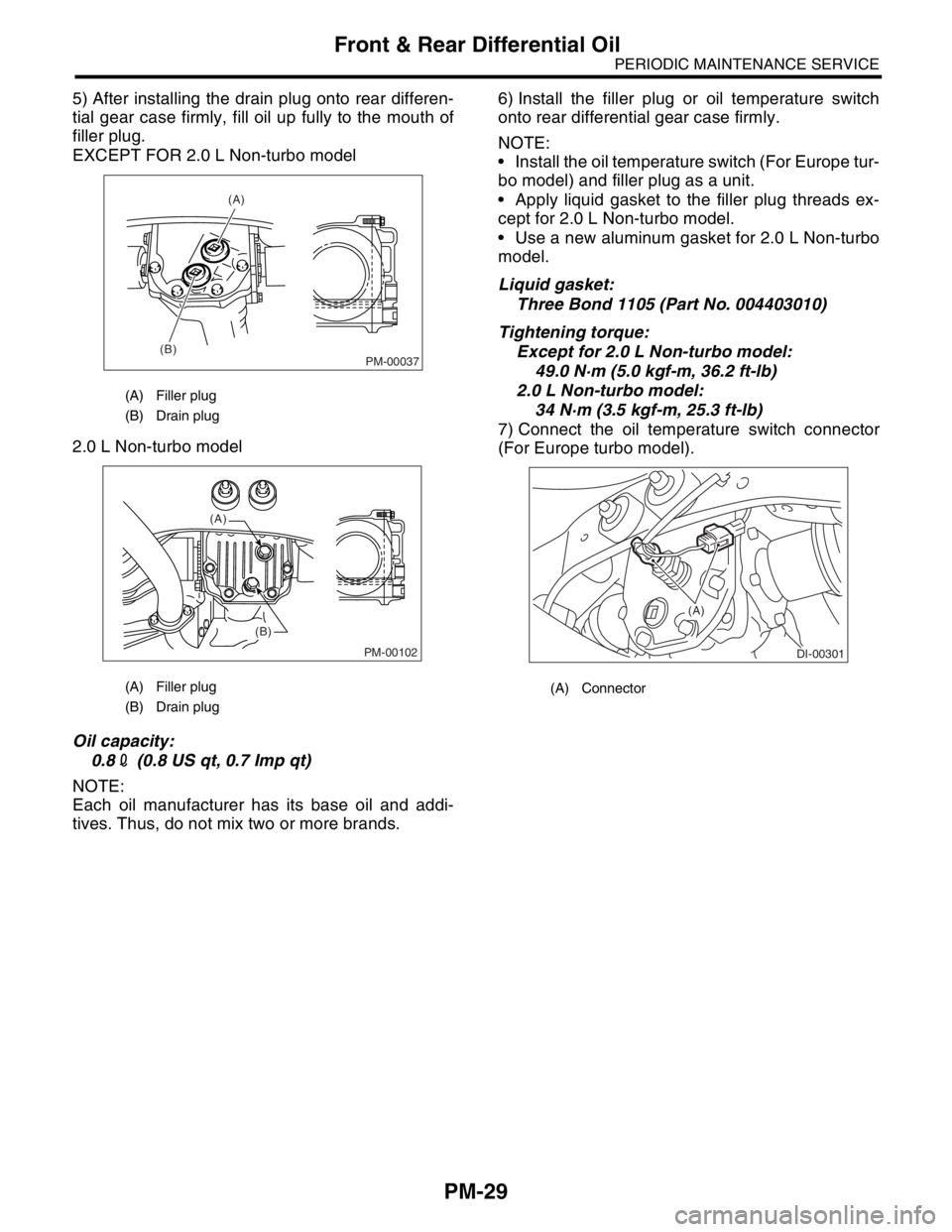
5) After installing the drain plug onto rear differen-
tial gear case firmly, fill oil up fully to the mouth of
filler plug.
EXCEPT FOR 2.0 L Non-turbo model
2.0 L Non-turbo model
Oil capacity:
0.82 (0.8 US qt, 0.7 Imp qt)
NOTE:
Each oil manufacturer has its base oil and addi-
tives. Thus, do not mix two or more brands.6) Install the filler plug or oil temperature switch
onto rear differential gear case firmly.
NOTE:
Install the oil temperature switch (For Europe tur-
bo model) and filler plug as a unit.
Apply liquid gasket to the filler plug threads ex-
cept for 2.0 L Non-turbo model.
Use a new aluminum gasket for 2.0 L Non-turbo
model.
Liquid gasket:
Three Bond 1105 (Part No. 004403010)
Tightening torque:
Except for 2.0 L Non-turbo model:
49.0 N·m (5.0 kgf-m, 36.2 ft-lb)
2.0 L Non-turbo model:
34 N·m (3.5 kgf-m, 25.3 ft-lb)
7) Connect the oil temperature switch connector
(For Europe turbo model).
(A) Filler plug
(B) Drain plug
(A) Filler plug
(B) Drain plug
PM-00037
(A)
(B)
PM-00102
(A)
(B)
(A) Connector
DI-00301
(A)
Page 767 of 2870
PM-30
PERIODIC MAINTENANCE SERVICE
Brake Line
18.Brake Line
A: INSPECTION
1. BRAKE LINE
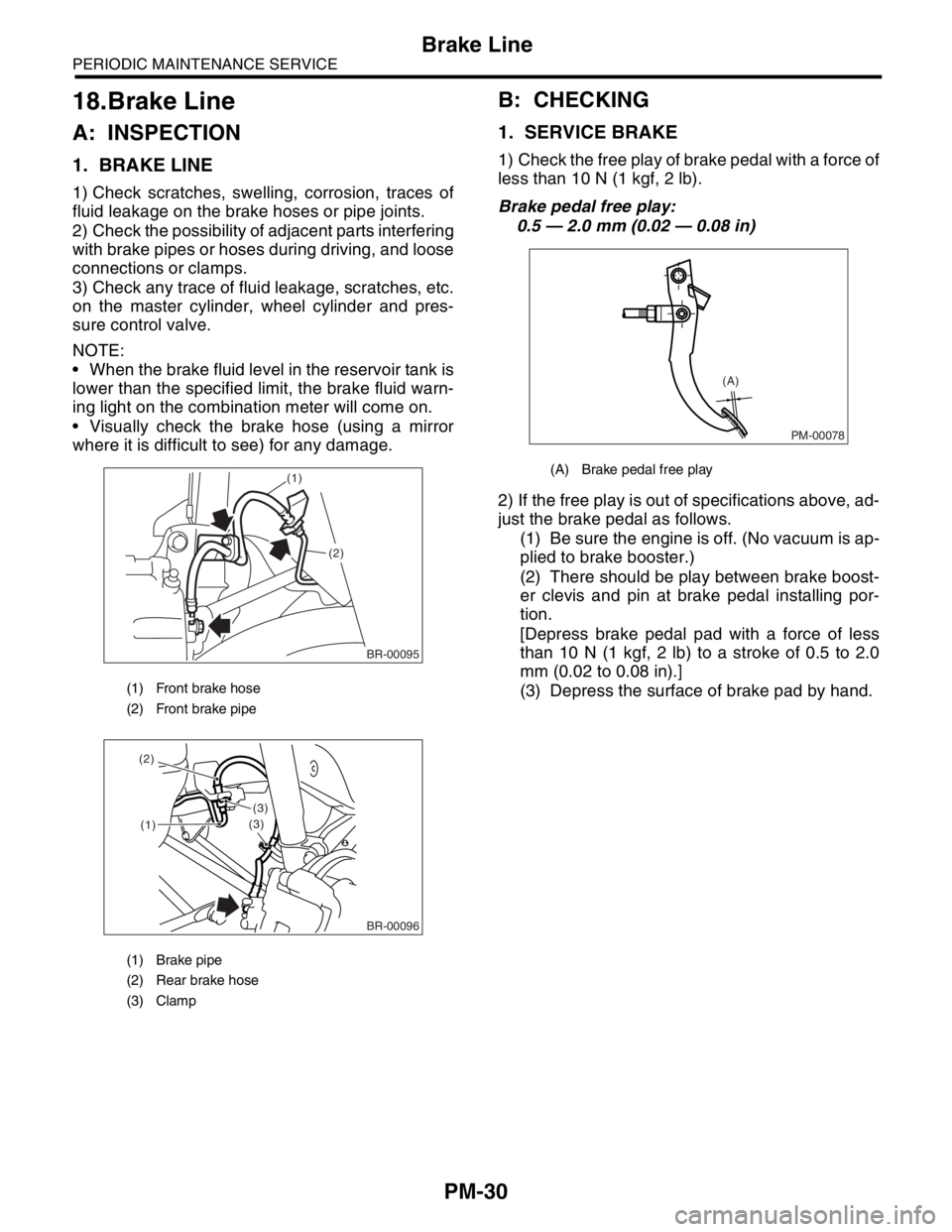
1) Check scratches, swelling, corrosion, traces of
fluid leakage on the brake hoses or pipe joints.
2) Check the possibility of adjacent parts interfering
with brake pipes or hoses during driving, and loose
connections or clamps.
3) Check any trace of fluid leakage, scratches, etc.
on the master cylinder, wheel cylinder and pres-
sure control valve.
NOTE:
When the brake fluid level in the reservoir tank is
lower than the specified limit, the brake fluid warn-
ing light on the combination meter will come on.
Visually check the brake hose (using a mirror
where it is difficult to see) for any damage.
B: CHECKING
1. SERVICE BRAKE
1) Check the free play of brake pedal with a force of
less than 10 N (1 kgf, 2 lb).
Brake pedal free play:
0.5 — 2.0 mm (0.02 — 0.08 in)
2) If the free play is out of specifications above, ad-
just the brake pedal as follows.
(1) Be sure the engine is off. (No vacuum is ap-
plied to brake booster.)
(2) There should be play between brake boost-
er clevis and pin at brake pedal installing por-
tion.
[Depress brake pedal pad with a force of less
than 10 N (1 kgf, 2 lb) to a stroke of 0.5 to 2.0
mm (0.02 to 0.08 in).]
(3) Depress the surface of brake pad by hand.
(1) Front brake hose
(2) Front brake pipe
(1) Brake pipe
(2) Rear brake hose
(3) Clamp
BR-00095
(1)
(2)
(1)
(3)
(3) (2)
BR-00096
(A) Brake pedal free play
PM-00078
(A)
Page 768 of 2870
PM-31
PERIODIC MAINTENANCE SERVICE
Brake Line
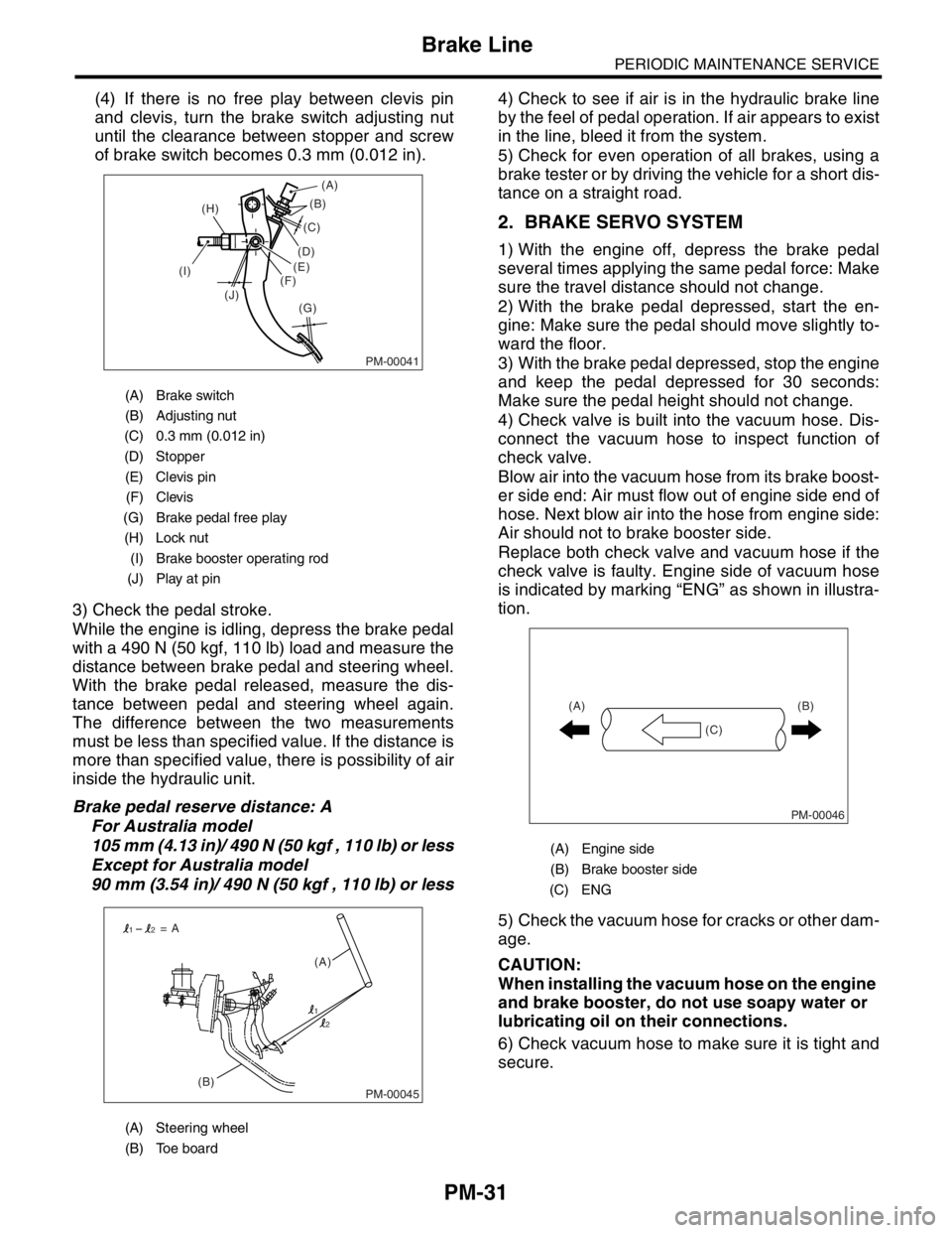
(4) If there is no free play between clevis pin
and clevis, turn the brake switch adjusting nut
until the clearance between stopper and screw
of brake switch becomes 0.3 mm (0.012 in).
3) Check the pedal stroke.
While the engine is idling, depress the brake pedal
with a 490 N (50 kgf, 110 lb) load and measure the
distance between brake pedal and steering wheel.
With the brake pedal released, measure the dis-
tance between pedal and steering wheel again.
The difference between the two measurements
must be less than specified value. If the distance is
more than specified value, there is possibility of air
inside the hydraulic unit.
Brake pedal reserve distance: A
For Australia model
105 mm (4.13 in)/ 490 N (50 kgf , 110 lb) or less
Except for Australia model
90 mm (3.54 in)/ 490 N (50 kgf , 110 lb) or less4) Check to see if air is in the hydraulic brake line
by the feel of pedal operation. If air appears to exist
in the line, bleed it from the system.
5) Check for even operation of all brakes, using a
brake tester or by driving the vehicle for a short dis-
tance on a straight road.
2. BRAKE SERVO SYSTEM
1) With the engine off, depress the brake pedal
several times applying the same pedal force: Make
sure the travel distance should not change.
2) With the brake pedal depressed, start the en-
gine: Make sure the pedal should move slightly to-
ward the floor.
3) With the brake pedal depressed, stop the engine
and keep the pedal depressed for 30 seconds:
Make sure the pedal height should not change.
4) Check valve is built into the vacuum hose. Dis-
connect the vacuum hose to inspect function of
check valve.
Blow air into the vacuum hose from its brake boost-
er side end: Air must flow out of engine side end of
hose. Next blow air into the hose from engine side:
Air should not to brake booster side.
Replace both check valve and vacuum hose if the
check valve is faulty. Engine side of vacuum hose
is indicated by marking “ENG” as shown in illustra-
tion.
5) Check the vacuum hose for cracks or other dam-
age.
CAUTION:
When installing the vacuum hose on the engine
and brake booster, do not use soapy water or
lubricating oil on their connections.
6) Check vacuum hose to make sure it is tight and
secure.
(A) Brake switch
(B) Adjusting nut
(C) 0.3 mm (0.012 in)
(D) Stopper
(E) Clevis pin
(F) Clevis
(G) Brake pedal free play
(H) Lock nut
(I) Brake booster operating rod
(J) Play at pin
(A) Steering wheel
(B) Toe board
PM-00041
(B)
(G) (H)
(I)
(J)(C)
(D)
(E)
(F)(A)
PM-00045(B)(A) = A
1
12
2
(A) Engine side
(B) Brake booster side
(C) ENG
PM-00046
(B)
(C) (A)
Page 769 of 2870
PM-32
PERIODIC MAINTENANCE SERVICE
Brake Fluid
19.Brake Fluid
A: REPLACEMENT
1) Lift-up the vehicle.
2) Remove both front and rear wheels.
3) Draw out the brake fluid from master cylinder
with syringe.
4) Refill the reservoir tank with recommended
brake fluid.
Recommended brake fluid:
FMVSS No. 116, fresh DOT3 or DOT4 brake
fluid
CAUTION:
Avoid mixing different brands of brake fluid
to prevent degrading the quality of the fluid.
Be careful not to allow dirt or dust to get into
the reservoir tank.
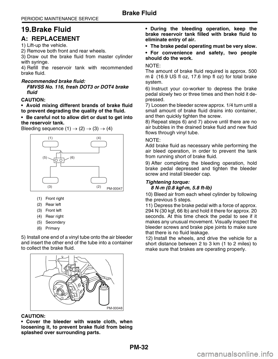
Bleeding sequence (1) → (2) → (3) → (4)
5) Install one end of a vinyl tube onto the air bleeder
and insert the other end of the tube into a container
to collect the brake fluid.
CAUTION:
Cover the bleeder with waste cloth, when
loosening it, to prevent brake fluid from being
splashed over surrounding parts. During the bleeding operation, keep the
brake reservoir tank filled with brake fluid to
eliminate entry of air.
The brake pedal operating must be very slow.
For convenience and safety, two people
should do the work.
NOTE:
The amount of brake fluid required is approx. 500
m2 (16.9 US fl oz, 17.6 Imp fl oz) for total brake
system.
6) Instruct your co-worker to depress the brake
pedal slowly two or three times and then hold it de-
pressed.
7) Loosen the bleeder screw approx. 1/4 turn until a
small amount of brake fluid drains into container,
and then quickly tighten the screw.
8) Repeat steps 6) and 7) above until there are no
air bubbles in the drained brake fluid and new fluid
flows through vinyl tube.
NOTE:
Add brake fluid as necessary while performing the
air bleed operation, in order to prevent the tank
from running short of brake fluid.
9) After completing the bleeding operation, hold
brake pedal depressed and tighten the bleeder
screw and install bleeder cap.
Tightening torque:
8 N·m (0.8 kgf-m, 5.8 ft-lb)
10) Bleed air from each wheel cylinder by following
the previous 5 steps.
11) Depress the brake pedal with a force of approx.
294 N (30 kgf, 66 lb) and hold it there for approx. 20
seconds. At this time check the pedal to see if it
makes any unusual movement. Visually inspect the
bleeder screws and brake pipe joints to make sure
that there is no fluid leakage.
12) Install the wheels, and drive the vehicle for a
short distance between 2 to 3 km (1 to 2 miles) to
make sure that brakes are operating properly.
(1) Front right
(2) Rear left
(3) Front left
(4) Rear right
(5) Secondary
(6) Primary
(1) (4)
(2) (3) (5) (6)
PM-00047
PM-00048
Page 770 of 2870
PM-33
PERIODIC MAINTENANCE SERVICE
Disc Brake Pads and Discs
20.Disc Brake Pads and Discs
A: INSPECTION
1. DISC BRAKE PAD AND DISC
1) Lift-up the vehicle. Then remove the wheels.
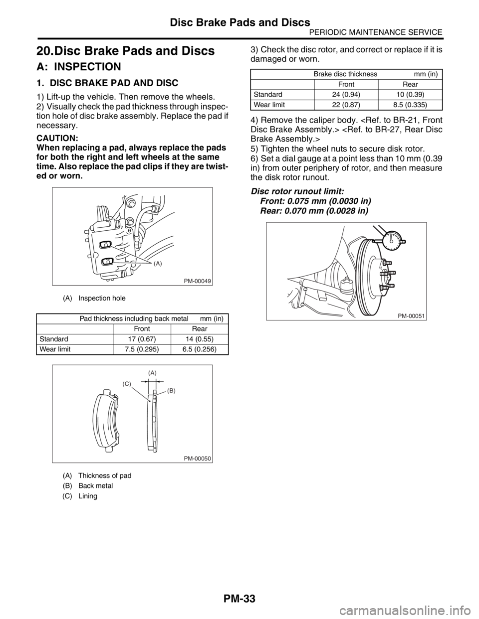
2) Visually check the pad thickness through inspec-
tion hole of disc brake assembly. Replace the pad if
necessary.
CAUTION:
When replacing a pad, always replace the pads
for both the right and left wheels at the same
time. Also replace the pad clips if they are twist-
ed or worn.3) Check the disc rotor, and correct or replace if it is
damaged or worn.
4) Remove the caliper body.
5) Tighten the wheel nuts to secure disk rotor.
6) Set a dial gauge at a point less than 10 mm (0.39
in) from outer periphery of rotor, and then measure
the disk rotor runout.
Disc rotor runout limit:
Front: 0.075 mm (0.0030 in)
Rear: 0.070 mm (0.0028 in)
(A) Inspection hole
Pad thickness including back metal mm (in)
Front Rear
Standard 17 (0.67) 14 (0.55)
Wear limit 7.5 (0.295) 6.5 (0.256)
(A) Thickness of pad
(B) Back metal
(C) Lining
PM-00049
(A)
PM-00050
(A)
(C)
(B)
Brake disc thickness mm (in)
Front Rear
Standard 24 (0.94) 10 (0.39)
Wear limit 22 (0.87) 8.5 (0.335)
PM-00051