SUBARU FORESTER 2004 Service Repair Manual
Manufacturer: SUBARU, Model Year: 2004, Model line: FORESTER, Model: SUBARU FORESTER 2004Pages: 2870, PDF Size: 38.67 MB
Page 921 of 2870
ME(H4SO)-52
MECHANICAL
Timing Belt
2. AUTOMATIC BELT TENSION ADJUST-
ER
1) Visually check oil seals for leaks, and rod ends
for abnormal wear or scratches. If necessary, re-
place faulty parts.
2) Check that the adjuster rod does not move when
a pressure of 294 N (30 kgf, 66 lb) is applied to it.
This is to check adjuster rod stiffness.
3) If the adjuster rod is not stiff and moves freely
when applying 294 N (30 kgf, 66 lb), check it using
the following procedures:
(1) Slowly press the adjuster rod down to the
end surface of the cylinder. Repeat this motion 2
or 3 times.
(2) With the adjuster rod moved all the way up,
apply a pressure of 294 N (30 kgf, 66 lb) to it.
Check adjuster rod stiffness.
(3) If the adjuster rod is not stiff and moves
down, replace the automatic belt tension adjust-
er assembly with a new one.
CAUTION:
Always use a vertical type pressing tool to
move the adjuster rod down.
Do not use a lateral type vise.
Push the adjuster rod vertically.
Press-in the adjuster rod gradually taking
more than 3 minutes.
Do not allow press pressure to exceed 9,807
N (1,000 kgf, 2,205 lb).
Press the adjuster rod as far as the end sur-
face of the cylinder. Do not press the adjuster
rod into the cylinder. Doing so may damage the
cylinder.
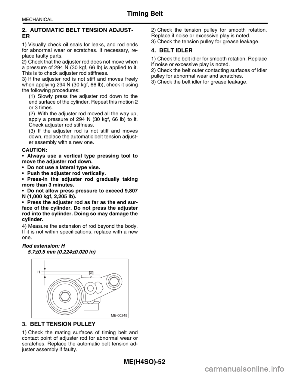
4) Measure the extension of rod beyond the body.
If it is not within specifications, replace with a new
one.
Rod extension: H
5.7
±0.5 mm (0.224±0.020 in)
3. BELT TENSION PULLEY
1) Check the mating surfaces of timing belt and
contact point of adjuster rod for abnormal wear or
scratches. Replace the automatic belt tension ad-
juster assembly if faulty.2) Check the tension pulley for smooth rotation.
Replace if noise or excessive play is noted.
3) Check the tension pulley for grease leakage.
4. BELT IDLER
1) Check the belt idler for smooth rotation. Replace
if noise or excessive play is noted.
2) Check the belt outer contacting surfaces of idler
pulley for abnormal wear and scratches.
3) Check the belt idler for grease leakage.
ME-00249
H
Page 922 of 2870
FUJI HEAVY INDUSTRIES LTD. G8080GE2
2004 FORESTER SERVICE MANUAL QUICK REFERENCE INDEX
ENGINE SECTION 1
This service manual has been prepared
to provide SUBARU service personnel
with the necessary information and data
for the correct maintenance and repair
of SUBARU vehicles.
This manual includes the procedures
for maintenance, disassembling, reas-
sembling, inspection and adjustment of
components and diagnostics for guid-
ance of experienced mechanics.
Please peruse and utilize this manual
fully to ensure complete repair work for
satisfying our customers by keeping
their vehicle in optimum condition.
When replacement of parts during
repair work is needed, be sure to use
SUBARU genuine parts.
All information, illustration and specifi-
cations contained in this manual are
based on the latest product information
available at the time of publication
approval.FUEL INJECTION (FUEL SYSTEM) FU(H4SO)
EMISSION CONTROL
(AUX. EMISSION CONTROL DEVICE)EC(H4SO)
INTAKE (INDUCTION) IN(H4SO)
MECHANICAL ME(H4SO)
EXHAUST EX(H4SO)
COOLING CO(H4SO)
LUBRICATION LU(H4SO)
SPEED CONTROL SYSTEM SP(H4SO)
IGNITION IG(H4SO)
STARTING/CHARGING SYSTEM SC(H4SO)
ENGINE (DIAGNOSTIC) EN(H4SO)
Page 923 of 2870

MECHANICAL
ME(H4SO)
Page
1. General Description ....................................................................................2
2. Compression .............................................................................................25
3. Idle Speed .................................................................................................26
4. Ignition Timing ...........................................................................................27
5. Intake Manifold Vacuum............................................................................28
6. Engine Oil Pressure ..................................................................................29
7. Fuel Pressure ............................................................................................30
8. Valve Clearance ........................................................................................31
9. Engine Assembly ......................................................................................34
10. Engine Mounting .......................................................................................41
11. Preparation for Overhaul ...........................................................................42
12. V-belt .........................................................................................................43
13. Crank Pulley ..............................................................................................45
14. Timing Belt Cover......................................................................................47
15. Timing Belt ................................................................................................48
16. Cam Sprocket ...........................................................................................53
17. Crank Sprocket .........................................................................................55
18. Valve Rocker Assembly ............................................................................56
19. Camshaft ...................................................................................................58
20. Cylinder Head ...........................................................................................62
21. Cylinder Block ...........................................................................................69
22. Engine Trouble in General ........................................................................91
23. Engine Noise .............................................................................................96
Page 924 of 2870
ME(H4SO)-53
MECHANICAL
Cam Sprocket
16.Cam Sprocket
A: REMOVAL
1. REMOVAL
1) Remove the V-belt.
2) Remove the crank pulley.
3) Remove the belt cover.
4) Remove the timing belt assembly.
5) Remove the camshaft position sensor.
Sensor.>
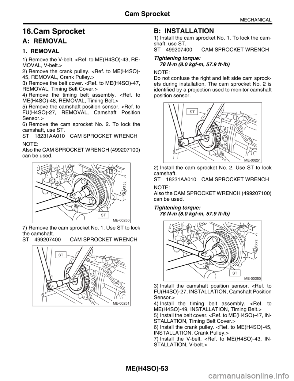
6) Remove the cam sprocket No. 2. To lock the
camshaft, use ST.
ST 18231AA010 CAM SPROCKET WRENCH
NOTE:
Also the CAM SPROCKET WRENCH (499207100)
can be used.
7) Remove the cam sprocket No. 1. Use ST to lock
the camshaft.
ST 499207400 CAM SPROCKET WRENCH
B: INSTALLATION
1) Install the cam sprocket No. 1. To lock the cam-
shaft, use ST.
ST 499207400 CAM SPROCKET WRENCH
Tightening torque:
78 N
⋅m (8.0 kgf-m, 57.9 ft-lb)
NOTE:
Do not confuse the right and left side cam sprock-
ets during installation. The cam sprocket No. 2 is
identified by a projection used to monitor camshaft
position sensor.
2) Install the cam sprocket No. 2. Use ST to lock
camshaft.
ST 18231AA010 CAM SPROCKET WRENCH
NOTE:
Also the CAM SPROCKET WRENCH (499207100)
can be used.
Tightening torque:
78 N
⋅m (8.0 kgf-m, 57.9 ft-lb)
3) Install the camshaft position sensor.
Sensor.>
4) Install the timing belt assembly.
5) Install the belt cover.
6) Install the crank pulley.
7) Install the V-belt.
ME-00250
ST
ME-00251
ST
ME-00251
ST
ME-00250
ST
Page 925 of 2870

ME(H4SO)-54
MECHANICAL
Cam Sprocket
C: INSPECTION
1) Check the cam sprocket teeth for abnormal wear
and scratches.
2) Make sure there is no free play between cam
sprocket and key.
3) Check the cam sprocket notch for sensor for
damage and contamination of foreign matter.
Page 926 of 2870
ME(H4SO)-55
MECHANICAL
Crank Sprocket
17.Crank Sprocket
A: REMOVAL
1) Remove the V-belt.
2) Remove the crank pulley.
3) Remove the belt cover.
4) Remove the timing belt assembly.
5) Remove the cam sprocket.
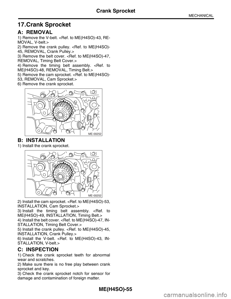
6) Remove the crank sprocket.
B: INSTALLATION
1) Install the crank sprocket.
2) Install the cam sprocket.
3) Install the timing belt assembly.
4) Install the belt cover.
5) Install the crank pulley.
6) Install the V-belt.
C: INSPECTION
1) Check the crank sprocket teeth for abnormal
wear and scratches.
2) Make sure there is no free play between crank
sprocket and key.
3) Check the crank sprocket notch for sensor for
damage and contamination of foreign matter.
ME-00252
ME-00252
Page 927 of 2870
ME(H4SO)-56
MECHANICAL
Valve Rocker Assembly
18.Valve Rocker Assembly
A: REMOVAL
1) Remove the V-belt.
2) Remove the crank pulley.
3) Remove the belt cover.
4) Remove the timing belt assembly.
5) Remove the cam sprocket.
6) Disconnect the PCV hose and remove rocker
cover.
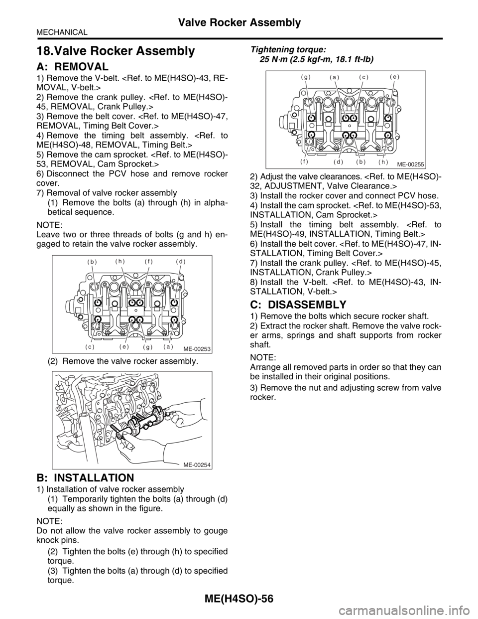
7) Removal of valve rocker assembly
(1) Remove the bolts (a) through (h) in alpha-
betical sequence.
NOTE:
Leave two or three threads of bolts (g and h) en-
gaged to retain the valve rocker assembly.
(2) Remove the valve rocker assembly.
B: INSTALLATION
1) Installation of valve rocker assembly
(1) Temporarily tighten the bolts (a) through (d)
equally as shown in the figure.
NOTE:
Do not allow the valve rocker assembly to gouge
knock pins.
(2) Tighten the bolts (e) through (h) to specified
torque.
(3) Tighten the bolts (a) through (d) to specified
torque.Tightening torque:
25 N
⋅m (2.5 kgf-m, 18.1 ft-lb)
2) Adjust the valve clearances.
3) Install the rocker cover and connect PCV hose.
4) Install the cam sprocket.
5) Install the timing belt assembly.
6) Install the belt cover.
7) Install the crank pulley.
8) Install the V-belt.
C: DISASSEMBLY
1) Remove the bolts which secure rocker shaft.
2) Extract the rocker shaft. Remove the valve rock-
er arms, springs and shaft supports from rocker
shaft.
NOTE:
Arrange all removed parts in order so that they can
be installed in their original positions.
3) Remove the nut and adjusting screw from valve
rocker.
ME-00253(a) (b)
(c)(d)
(e)(f)
(g) (h)
ME-00254
ME-00255
(a)
(b)(c)
(d)(e)
(f)(g)
(h)
Page 928 of 2870
ME(H4SO)-57
MECHANICAL
Valve Rocker Assembly
D: ASSEMBLY
1) Install the adjusting screw and nut to valve rock-
er.
2) Arrange the valve rocker arms, springs and shaft
supports in assembly order and insert valve rocker
shaft.
Tightening torque (Shaft supports installing
bolts):
5 N
⋅m (0.5 kgf-m, 3.6 ft-lb)
NOTE:
Valve rocker arms, rocker shaft and shaft supports
have identification marks. Ensure the parts with
same markings are properly assembled.
3) Install the valve rocker shaft securing bolts.
E: INSPECTION
1. VALVE ROCKER ARM AND ROCKER
SHAFT
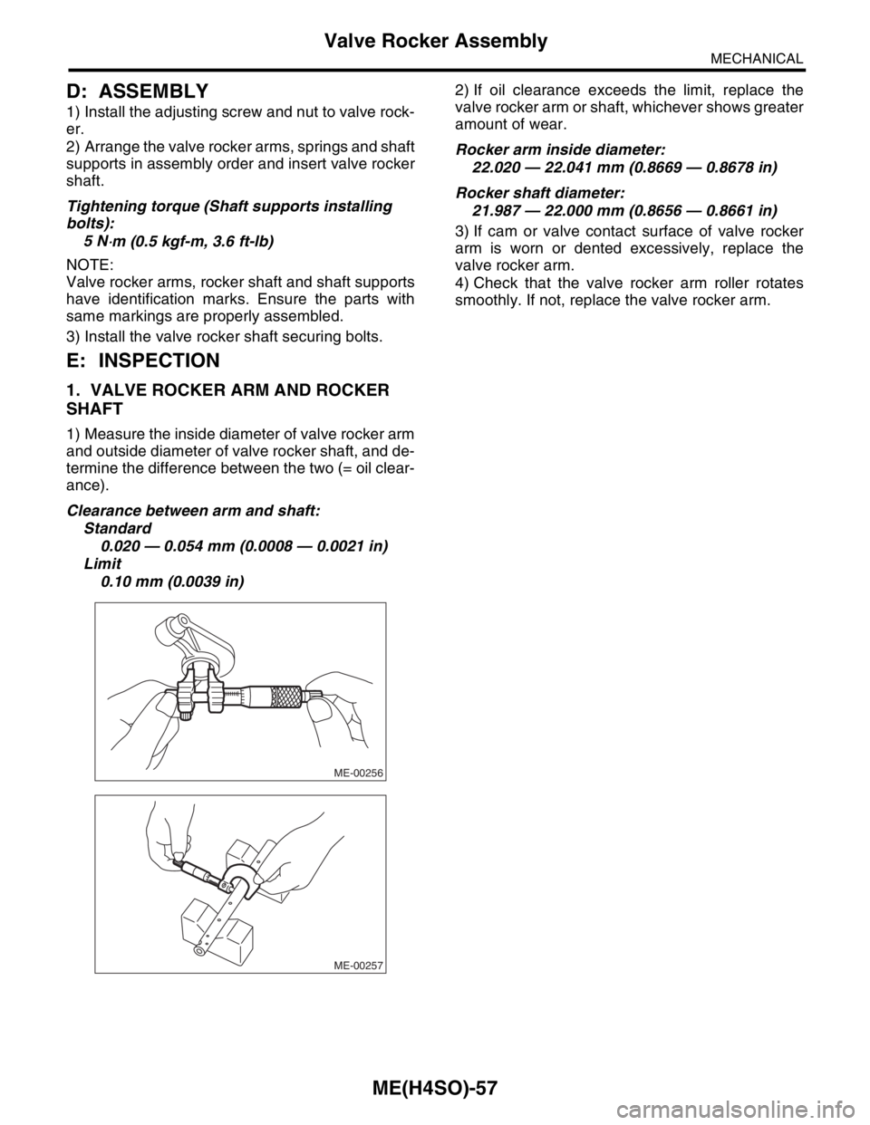
1) Measure the inside diameter of valve rocker arm
and outside diameter of valve rocker shaft, and de-
termine the difference between the two (= oil clear-
ance).
Clearance between arm and shaft:
Standard
0.020 — 0.054 mm (0.0008 — 0.0021 in)
Limit
0.10 mm (0.0039 in)2) If oil clearance exceeds the limit, replace the
valve rocker arm or shaft, whichever shows greater
amount of wear.
Rocker arm inside diameter:
22.020 — 22.041 mm (0.8669 — 0.8678 in)
Rocker shaft diameter:
21.987 — 22.000 mm (0.8656 — 0.8661 in)
3) If cam or valve contact surface of valve rocker
arm is worn or dented excessively, replace the
valve rocker arm.
4) Check that the valve rocker arm roller rotates
smoothly. If not, replace the valve rocker arm.
ME-00256
ME-00257
Page 929 of 2870
ME(H4SO)-58
MECHANICAL
Camshaft
19.Camshaft
A: REMOVAL
1) Remove the V-belt.
2) Remove the crank pulley.
3) Remove the belt cover.
4) Remove the timing belt assembly.
5) Remove the cam sprocket.
6) Remove the crank sprocket.
7) Remove the belt cover No. 2 (LH).
8) Remove the belt cover No. 2 (RH).
NOTE:
Do not damage or lose the seal rubber when re-
moving belt covers.
9) Remove the tensioner bracket.
10) Remove the camshaft position sensor support.
(LH side only)
11) Remove the oil level gauge guide. (LH side only)
12) Remove the valve rocker assembly.
bly.>
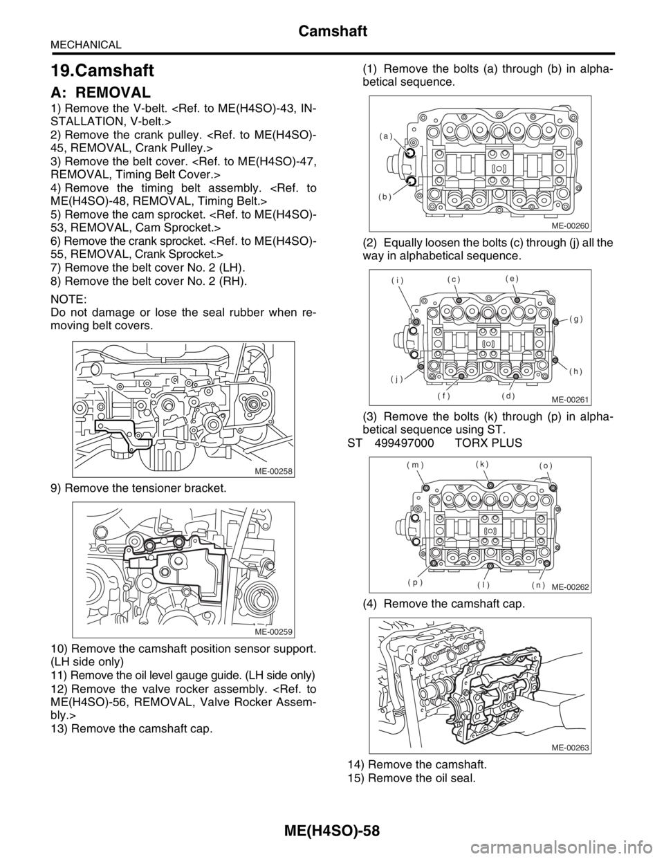
13) Remove the camshaft cap.(1) Remove the bolts (a) through (b) in alpha-
betical sequence.
(2) Equally loosen the bolts (c) through (j) all the
way in alphabetical sequence.
(3) Remove the bolts (k) through (p) in alpha-
betical sequence using ST.
ST 499497000 TORX PLUS
(4) Remove the camshaft cap.
14) Remove the camshaft.
15) Remove the oil seal.
ME-00258
ME-00259
ME-00260
(b)(a)
ME-00261
(c)(e)
(g)
(h)
(d) (f) (j)(i)
ME-00262
(k)
(o)
(n) (l) (p) (m)
ME-00263
Page 930 of 2870
ME(H4SO)-59
MECHANICAL
Camshaft
16) Remove the plug from rear side of camshaft.
CAUTION:
Do not remove the oil seal unless necessary.
Do not scratch the journal surface when re-
moving oil seal.
B: INSTALLATION
1) Apply a coat of engine oil to the camshaft jour-
nals, and then install the camshaft.
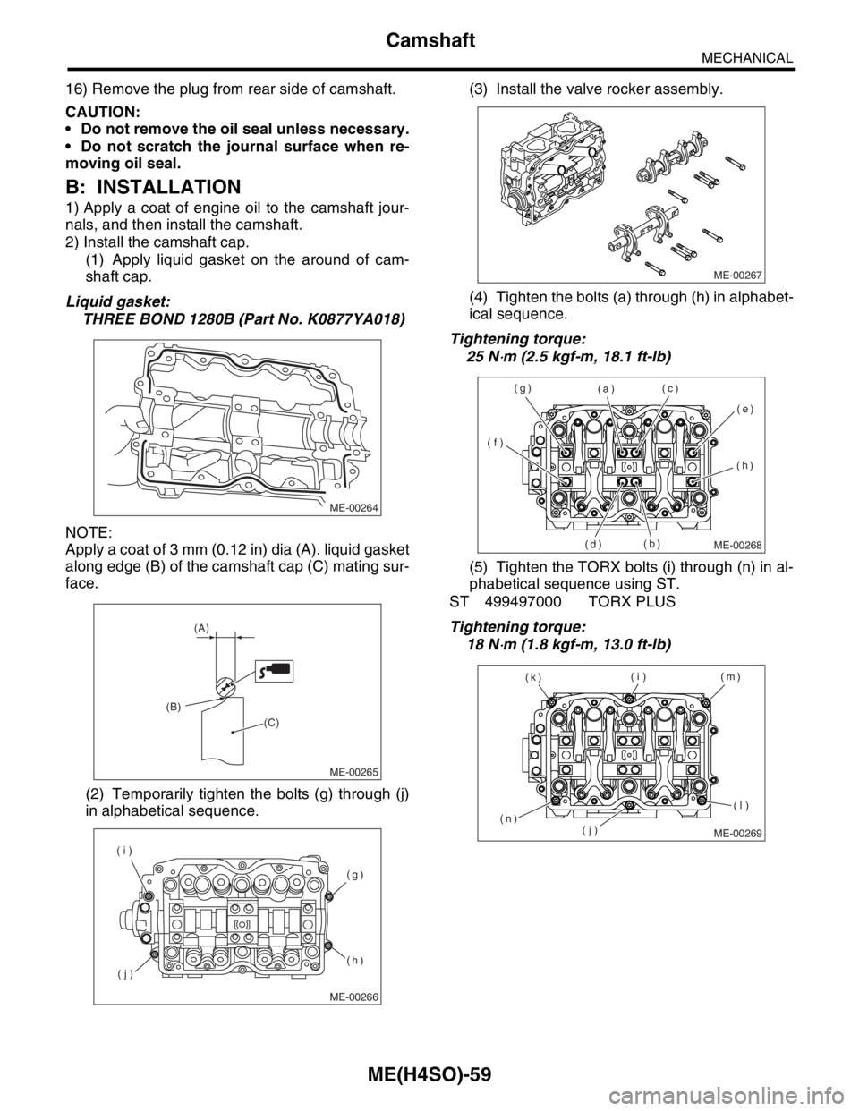
2) Install the camshaft cap.
(1) Apply liquid gasket on the around of cam-
shaft cap.
Liquid gasket:
THREE BOND 1280B (Part No. K0877YA018)
NOTE:
Apply a coat of 3 mm (0.12 in) dia (A). liquid gasket
along edge (B) of the camshaft cap (C) mating sur-
face.
(2) Temporarily tighten the bolts (g) through (j)
in alphabetical sequence.(3) Install the valve rocker assembly.
(4) Tighten the bolts (a) through (h) in alphabet-
ical sequence.
Tightening torque:
25 N
⋅m (2.5 kgf-m, 18.1 ft-lb)
(5) Tighten the TORX bolts (i) through (n) in al-
phabetical sequence using ST.
ST 499497000 TORX PLUS
Tightening torque:
18 N
⋅m (1.8 kgf-m, 13.0 ft-lb)
ME-00264
ME-00265
(A)
(B)
(C)
ME-00266
(g)
(h)
(j) (i)
ME-00267
ME-00268
(a)
(b)(c)
(d)(e)
(f)(g)
(h)
ME-00269
(i)
(j)(m)
(n)(k)
(l)