SUBARU FORESTER 2004 Service Repair Manual
Manufacturer: SUBARU, Model Year: 2004, Model line: FORESTER, Model: SUBARU FORESTER 2004Pages: 2870, PDF Size: 38.67 MB
Page 941 of 2870
ME(H4SO)-70
MECHANICAL
Cylinder Block
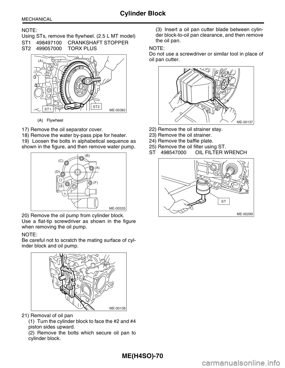
NOTE:
Using STs, remove the flywheel. (2.5 L MT model)
ST1 498497100 CRANKSHAFT STOPPER
ST2 499057000 TORX PLUS
17) Remove the oil separator cover.
18) Remove the water by-pass pipe for heater.
19) Loosen the bolts in alphabetical sequence as
shown in the figure, and then remove water pump.
20) Remove the oil pump from cylinder block.
Use a flat-tip screwdriver as shown in the figure
when removing the oil pump.
NOTE:
Be careful not to scratch the mating surface of cyl-
inder block and oil pump.
21) Removal of oil pan
(1) Turn the cylinder block to face the #2 and #4
piston sides upward.
(2) Remove the bolts which secure oil pan to
cylinder block.(3) Insert a oil pan cutter blade between cylin-
der block-to-oil pan clearance, and then remove
the oil pan.
NOTE:
Do not use a screwdriver or similar tool in place of
oil pan cutter.
22) Remove the oil strainer stay.
23) Remove the oil strainer.
24) Remove the baffle plate.
25) Remove the oil filter using ST.
ST 498547000 OIL FILTER WRENCH
(A) Flywheel
(A)
ME-00382
ST1ST2
ME-00333
(B)
(F) (D)(C)
(A)
(E)
ME-00138
ME-00137
ME-00299
ST
Page 942 of 2870
![SUBARU FORESTER 2004 Service Repair Manual ME(H4SO)-71
MECHANICAL
Cylinder Block
26) Remove the water pipe.
27) Remove the service hole cover and service
hole plugs using hexagon wrench [14 mm (0.55
in)].28) Rotate the crankshaft to bring #1 a SUBARU FORESTER 2004 Service Repair Manual ME(H4SO)-71
MECHANICAL
Cylinder Block
26) Remove the water pipe.
27) Remove the service hole cover and service
hole plugs using hexagon wrench [14 mm (0.55
in)].28) Rotate the crankshaft to bring #1 a](/img/17/57426/w960_57426-941.png)
ME(H4SO)-71
MECHANICAL
Cylinder Block
26) Remove the water pipe.
27) Remove the service hole cover and service
hole plugs using hexagon wrench [14 mm (0.55
in)].28) Rotate the crankshaft to bring #1 and #2 pis-
tons to bottom dead center position, and then re-
move the piston snap ring through service hole of
#1 and #2 cylinders using needle nose plier.
ME-00300
(1) Service hole plug (3) Snap ring (5) Service hole cover
(2) Gasket (4) Piston pin (6) O-ring
ME-00139
(3)
(4) (2)(1)
(3)
(4)
(5)
(6)
(2)(3)
(2)
(1)(3)(4)
(4)
(1)
ME-00140
ME-00141
Page 943 of 2870
ME(H4SO)-72
MECHANICAL
Cylinder Block
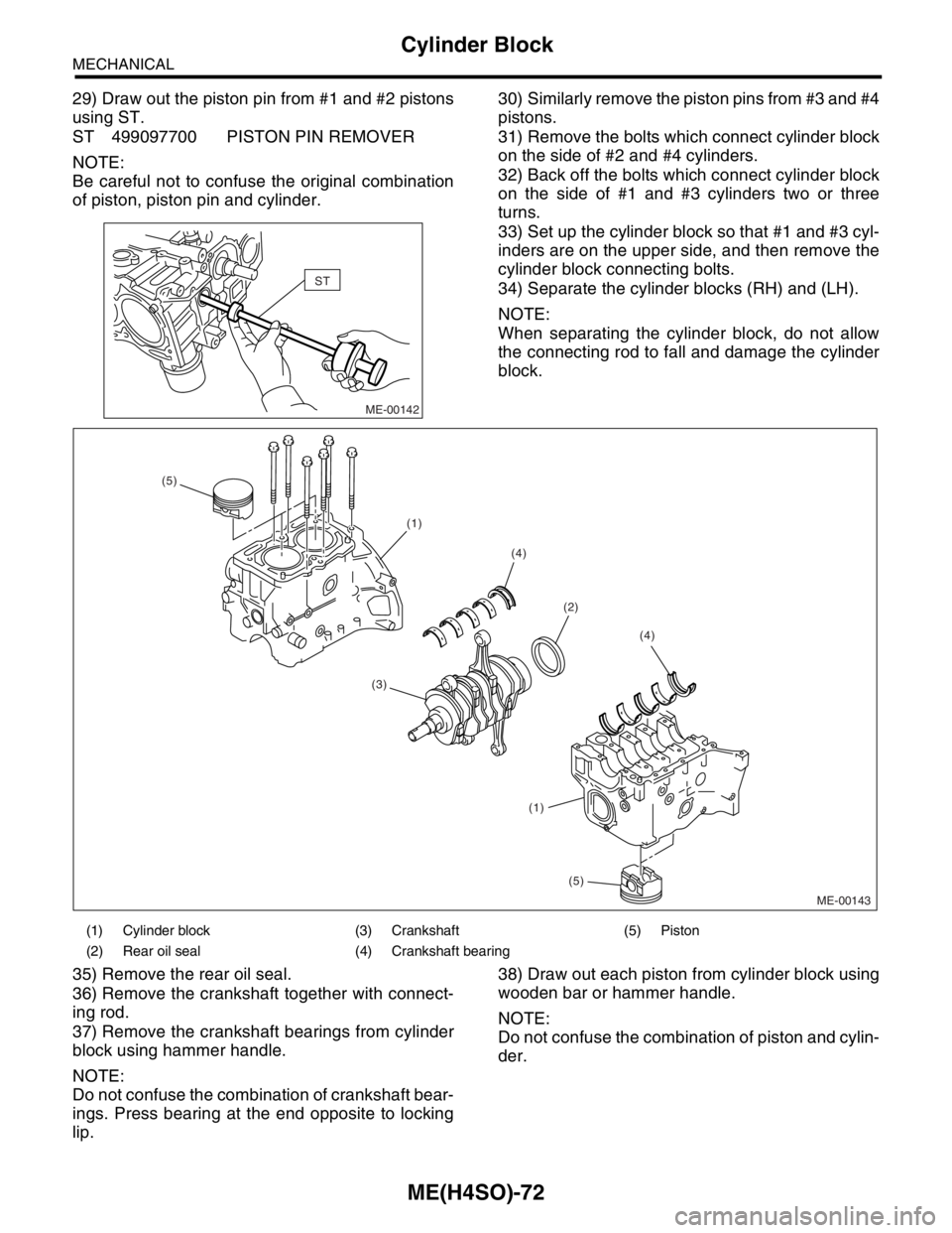
29) Draw out the piston pin from #1 and #2 pistons
using ST.
ST 499097700 PISTON PIN REMOVER
NOTE:
Be careful not to confuse the original combination
of piston, piston pin and cylinder.30) Similarly remove the piston pins from #3 and #4
pistons.
31) Remove the bolts which connect cylinder block
on the side of #2 and #4 cylinders.
32) Back off the bolts which connect cylinder block
on the side of #1 and #3 cylinders two or three
turns.
33) Set up the cylinder block so that #1 and #3 cyl-
inders are on the upper side, and then remove the
cylinder block connecting bolts.
34) Separate the cylinder blocks (RH) and (LH).
NOTE:
When separating the cylinder block, do not allow
the connecting rod to fall and damage the cylinder
block.
35) Remove the rear oil seal.
36) Remove the crankshaft together with connect-
ing rod.
37) Remove the crankshaft bearings from cylinder
block using hammer handle.
NOTE:
Do not confuse the combination of crankshaft bear-
ings. Press bearing at the end opposite to locking
lip.38) Draw out each piston from cylinder block using
wooden bar or hammer handle.
NOTE:
Do not confuse the combination of piston and cylin-
der.
ME-00142
ST
(1) Cylinder block (3) Crankshaft (5) Piston
(2) Rear oil seal (4) Crankshaft bearing
ME-00143
(2)
(3)(4)
(4) (5)
(5) (1) (1)
Page 944 of 2870
ME(H4SO)-73
MECHANICAL
Cylinder Block
B: INSTALLATION
NOTE:
Remove oil in the mating surface of bearing and
cylinder block before installation. Also apply a coat
of engine oil to crankshaft pins.
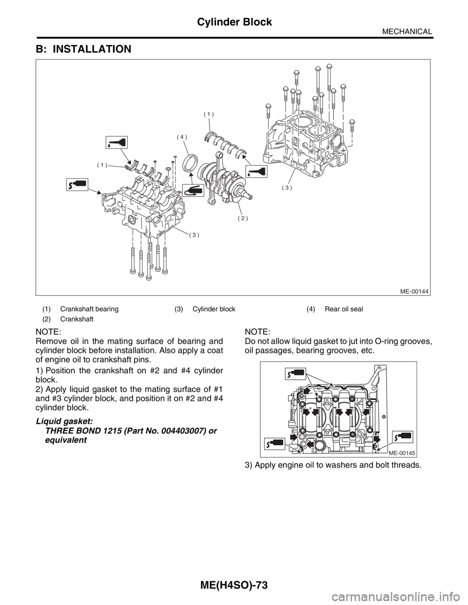
1) Position the crankshaft on #2 and #4 cylinder
block.
2) Apply liquid gasket to the mating surface of #1
and #3 cylinder block, and position it on #2 and #4
cylinder block.
Liquid gasket:
THREE BOND 1215 (Part No. 004403007) or
equivalentNOTE:
Do not allow liquid gasket to jut into O-ring grooves,
oil passages, bearing grooves, etc.
3) Apply engine oil to washers and bolt threads.
(1) Crankshaft bearing (3) Cylinder block (4) Rear oil seal
(2) Crankshaft
ME-00144
( 1 )
( 1 )
( 2 )
( 3 )
( 3 )
( 4 )
ME-00145
Page 945 of 2870
ME(H4SO)-74
MECHANICAL
Cylinder Block
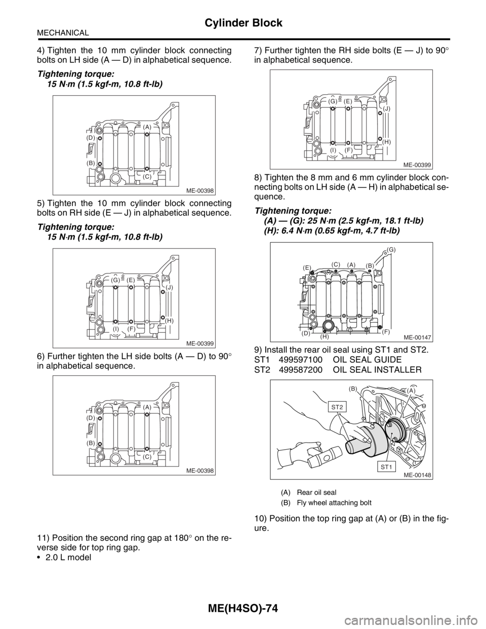
4) Tighten the 10 mm cylinder block connecting
bolts on LH side (A — D) in alphabetical sequence.
Tightening torque:
15 N
⋅m (1.5 kgf-m, 10.8 ft-lb)
5) Tighten the 10 mm cylinder block connecting
bolts on RH side (E — J) in alphabetical sequence.
Tightening torque:
15 N
⋅m (1.5 kgf-m, 10.8 ft-lb)
6) Further tighten the LH side bolts (A — D) to 90°
in alphabetical sequence.7) Further tighten the RH side bolts (E — J) to 90°
in alphabetical sequence.
8) Tighten the 8 mm and 6 mm cylinder block con-
necting bolts on LH side (A — H) in alphabetical se-
quence.
Tightening torque:
(A) — (G): 25 N
⋅m (2.5 kgf-m, 18.1 ft-lb)
(H): 6.4 N
⋅m (0.65 kgf-m, 4.7 ft-lb)
9) Install the rear oil seal using ST1 and ST2.
ST1 499597100 OIL SEAL GUIDE
ST2 499587200 OIL SEAL INSTALLER
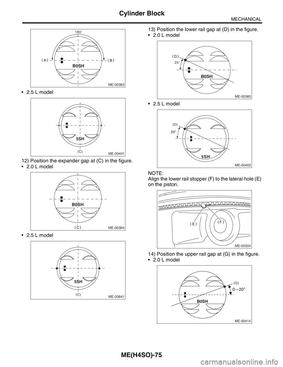
10) Position the top ring gap at (A) or (B) in the fig-
ure.
11) Position the second ring gap at 180° on the re-
verse side for top ring gap.
2.0 L model
ME-00398
(A)
(B)
(C) (D)
ME-00399
(E)(G)
(F)(I)
(J)
(H)
ME-00398
(A)
(B)
(C) (D)
(A) Rear oil seal
(B) Fly wheel attaching bolt
ME-00399
(E)(G)
(F)(I)
(J)
(H)
ME-00147
(B)(C)
(D)
(E)
(F)
(G)
(H)
(A)
ME-00148
ST1
ST2
(B)
(A)
Page 946 of 2870
ME(H4SO)-75
MECHANICAL
Cylinder Block
2.5 L model
12) Position the expander gap at (C) in the figure.
2.0 L model
2.5 L model13) Position the lower rail gap at (D) in the figure.
2.0 L model
2.5 L model
NOTE:
Align the lower rail stopper (F) to the lateral hole (E)
on the piston.
14) Position the upper rail gap at (G) in the figure.
2.0 L model
ME-00383
180�
B0SH
ME-00401(C)
5SH
ME-00384
B0SH
ME-00841
5SH
(C)ME-00385
25�
B0SH
ME-00402
(D)
5SH
ME-00304
(G)
B0SH
ME-00414
Page 947 of 2870
ME(H4SO)-76
MECHANICAL
Cylinder Block
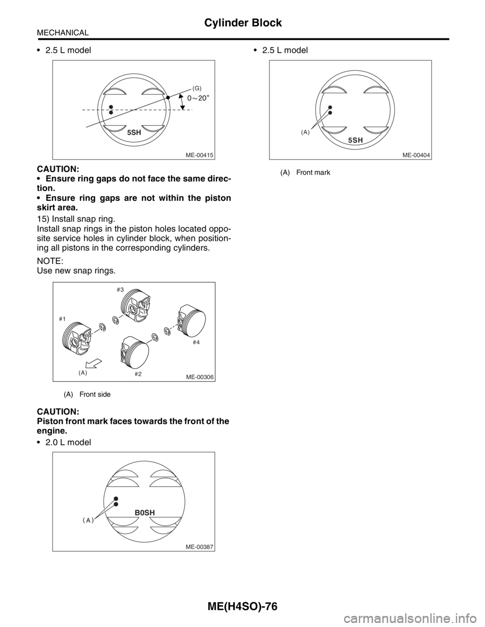
2.5 L model
CAUTION:
Ensure ring gaps do not face the same direc-
tion.
Ensure ring gaps are not within the piston
skirt area.
15) Install snap ring.
Install snap rings in the piston holes located oppo-
site service holes in cylinder block, when position-
ing all pistons in the corresponding cylinders.
NOTE:
Use new snap rings.
CAUTION:
Piston front mark faces towards the front of the
engine.
2.0 L model 2.5 L model
(A) Front side
ME-00415
5SH
(G)
ME-00306
#4 #3
#2 #1
(A)
ME-00387
B0SH
(A) Front mark
ME-00404
5SH
(A)
Page 948 of 2870
ME(H4SO)-77
MECHANICAL
Cylinder Block
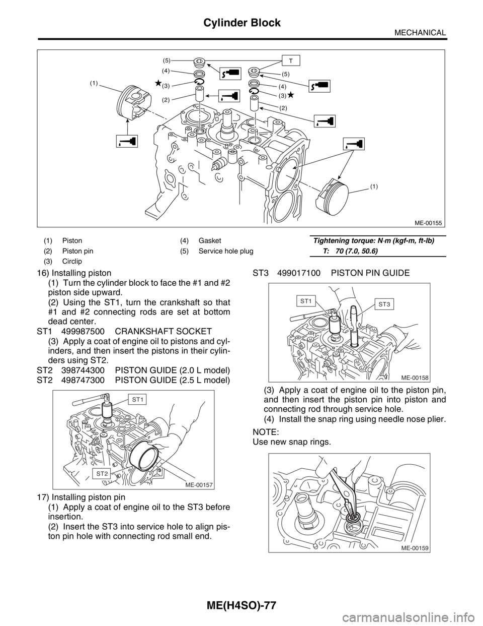
16) Installing piston
(1) Turn the cylinder block to face the #1 and #2
piston side upward.
(2) Using the ST1, turn the crankshaft so that
#1 and #2 connecting rods are set at bottom
dead center.
ST1 499987500 CRANKSHAFT SOCKET
(3) Apply a coat of engine oil to pistons and cyl-
inders, and then insert the pistons in their cylin-
ders using ST2.
ST2 398744300 PISTON GUIDE (2.0 L model)
ST2 498747300 PISTON GUIDE (2.5 L model)
17) Installing piston pin
(1) Apply a coat of engine oil to the ST3 before
insertion.
(2) Insert the ST3 into service hole to align pis-
ton pin hole with connecting rod small end.ST3 499017100 PISTON PIN GUIDE
(3) Apply a coat of engine oil to the piston pin,
and then insert the piston pin into piston and
connecting rod through service hole.
(4) Install the snap ring using needle nose plier.
NOTE:
Use new snap rings.
(1) Piston (4) GasketTightening torque: N⋅m (kgf-m, ft-lb)
(2) Piston pin (5) Service hole plugT: 70 (7.0, 50.6)
(3) Circlip
ME-00155
(1) (1)
(2)
(2) (3)
(3) (4)
(4) (5)
(5)
T
ME-00157
ST2
ST1
ME-00158
ST1ST3
ME-00159
Page 949 of 2870
ME(H4SO)-78
MECHANICAL
Cylinder Block
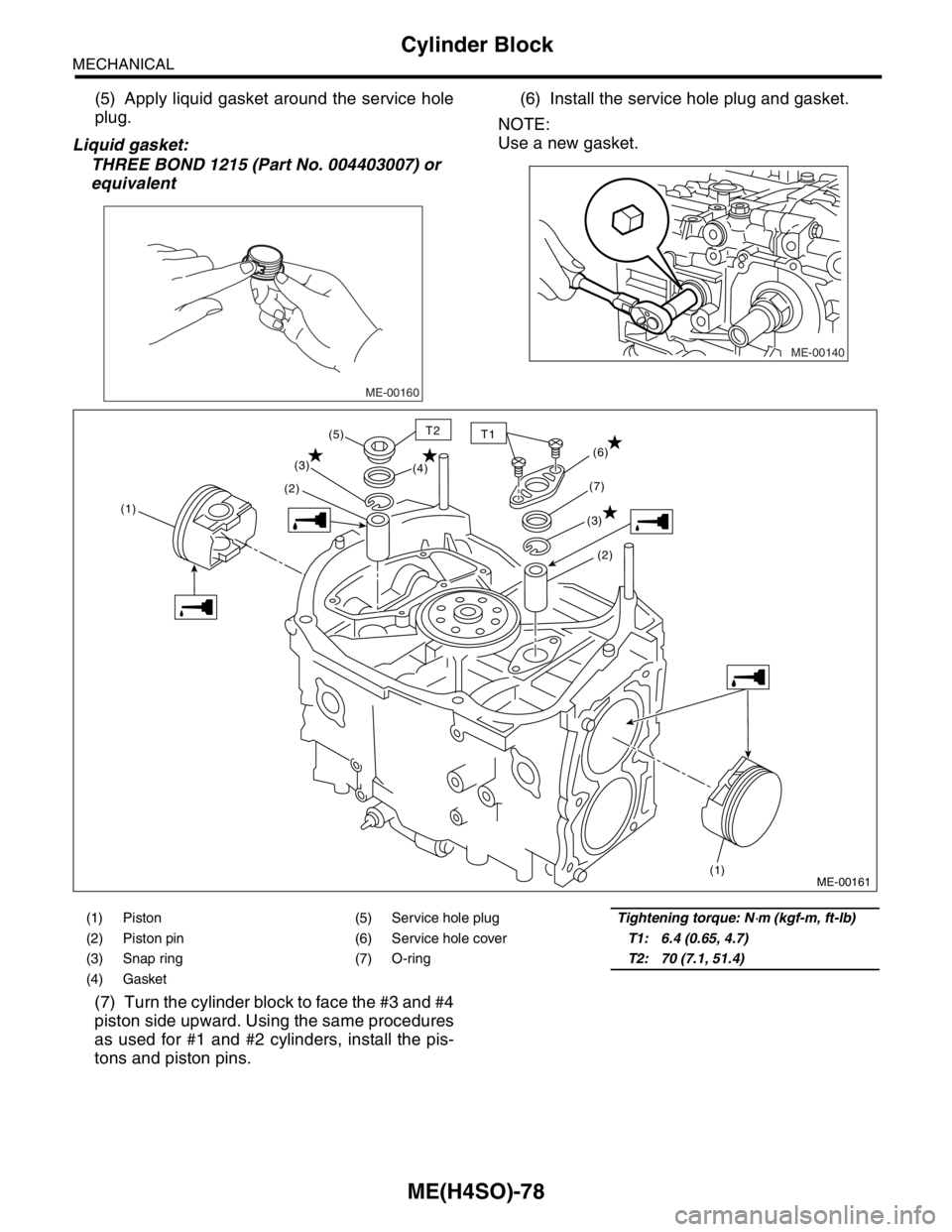
(5) Apply liquid gasket around the service hole
plug.
Liquid gasket:
THREE BOND 1215 (Part No. 004403007) or
equivalent(6) Install the service hole plug and gasket.
NOTE:
Use a new gasket.
(7) Turn the cylinder block to face the #3 and #4
piston side upward. Using the same procedures
as used for #1 and #2 cylinders, install the pis-
tons and piston pins.
ME-00160
ME-00140
(1) Piston (5) Service hole plugTightening torque: N⋅m (kgf-m, ft-lb)
(2) Piston pin (6) Service hole coverT1: 6.4 (0.65, 4.7)
(3) Snap ring (7) O-ringT2: 70 (7.1, 51.4)
(4) Gasket
(1)(2)(3)
(1)
(2) (6)
(3)(7) (4) (5)
ME-00161
T2T1
Page 950 of 2870
ME(H4SO)-79
MECHANICAL
Cylinder Block
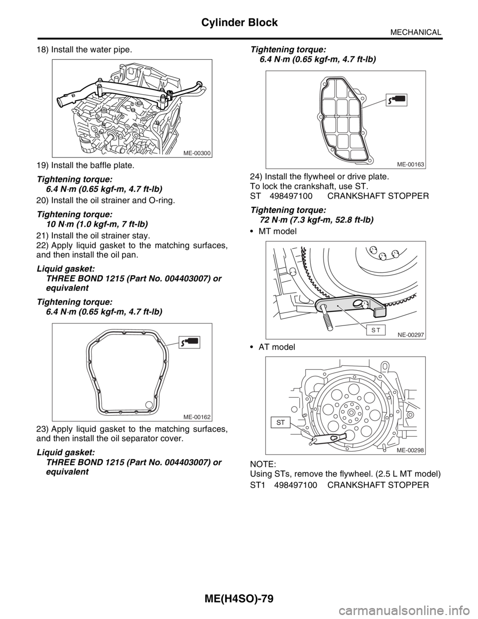
18) Install the water pipe.
19) Install the baffle plate.
Tightening torque:
6.4 N
⋅m (0.65 kgf-m, 4.7 ft-lb)
20) Install the oil strainer and O-ring.
Tightening torque:
10 N
⋅m (1.0 kgf-m, 7 ft-lb)
21) Install the oil strainer stay.
22) Apply liquid gasket to the matching surfaces,
and then install the oil pan.
Liquid gasket:
THREE BOND 1215 (Part No. 004403007) or
equivalent
Tightening torque:
6.4 N
⋅m (0.65 kgf-m, 4.7 ft-lb)
23) Apply liquid gasket to the matching surfaces,
and then install the oil separator cover.
Liquid gasket:
THREE BOND 1215 (Part No. 004403007) or
equivalentTightening torque:
6.4 N
⋅m (0.65 kgf-m, 4.7 ft-lb)
24) Install the flywheel or drive plate.
To lock the crankshaft, use ST.
ST 498497100 CRANKSHAFT STOPPER
Tightening torque:
72 N
⋅m (7.3 kgf-m, 52.8 ft-lb)
MT model
AT model
NOTE:
Using STs, remove the flywheel. (2.5 L MT model)
ST1 498497100 CRANKSHAFT STOPPER
ME-00300
ME-00162
ME-00163
NE-00297ST
ME-00298