SUBARU LEGACY 1999 Service Repair Manual
Manufacturer: SUBARU, Model Year: 1999, Model line: LEGACY, Model: SUBARU LEGACY 1999Pages: 1456, PDF Size: 59.93 MB
Page 1211 of 1456
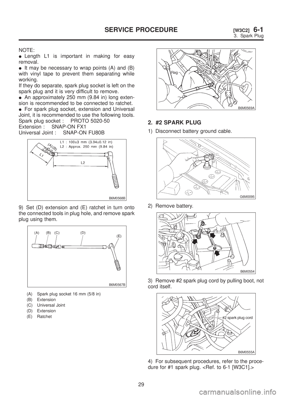
NOTE:
ILength L1 is important in making for easy
removal.
IIt may be necessary to wrap points (A) and (B)
with vinyl tape to prevent them separating while
working.
If they do separate, spark plug socket is left on the
spark plug and it is very difficult to remove.
IAn approximately 250 mm (9.84 in) long exten-
sion is recommended to be connected to ratchet.
IFor spark plug socket, extension and Universal
Joint, it is recommended to use the following tools.
Spark plug socket : PROTO 5020-50
Extension : SNAP-ON FX1
Universal Joint : SNAP-ON FU80B
B6M0568B
9) Set (D) extension and (E) ratchet in turn onto
the connected tools in plug hole, and remove spark
plug using them.
B6M0567B
(A) Spark plug socket 16 mm (5/8 in)
(B) Extension
(C) Universal Joint
(D) Extension
(E) Ratchet
B6M0569A
2. #2 SPARK PLUG
1) Disconnect battery ground cable.
G6M0095
2) Remove battery.
B6M0554
3) Remove #2 spark plug cord by pulling boot, not
cord itself.
B6M0555A
4) For subsequent procedures, refer to the proce-
dure for #1 spark plug.
29
[W3C2]6-1SERVICE PROCEDURE
3. Spark Plug
Page 1212 of 1456
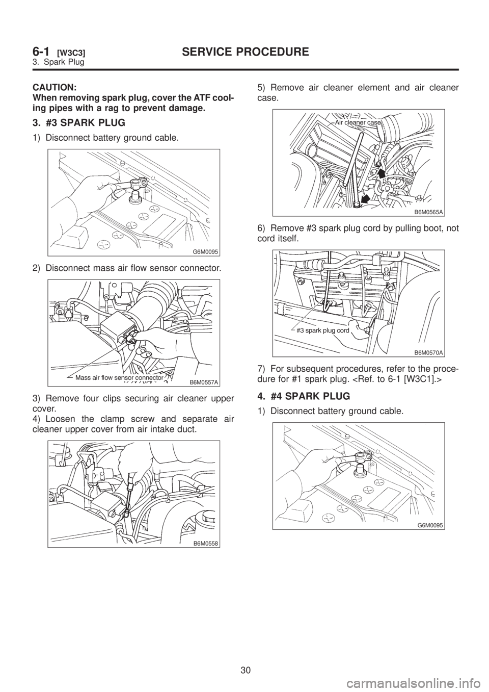
CAUTION:
When removing spark plug, cover the ATF cool-
ing pipes with a rag to prevent damage.
3. #3 SPARK PLUG
1) Disconnect battery ground cable.
G6M0095
2) Disconnect mass air flow sensor connector.
B6M0557A
3) Remove four clips securing air cleaner upper
cover.
4) Loosen the clamp screw and separate air
cleaner upper cover from air intake duct.
B6M0558
5) Remove air cleaner element and air cleaner
case.
B6M0565A
6) Remove #3 spark plug cord by pulling boot, not
cord itself.
B6M0570A
7) For subsequent procedures, refer to the proce-
dure for #1 spark plug.
4. #4 SPARK PLUG
1) Disconnect battery ground cable.
G6M0095
30
6-1[W3C3]SERVICE PROCEDURE
3. Spark Plug
Page 1213 of 1456
2) Remove battery.
B6M0554
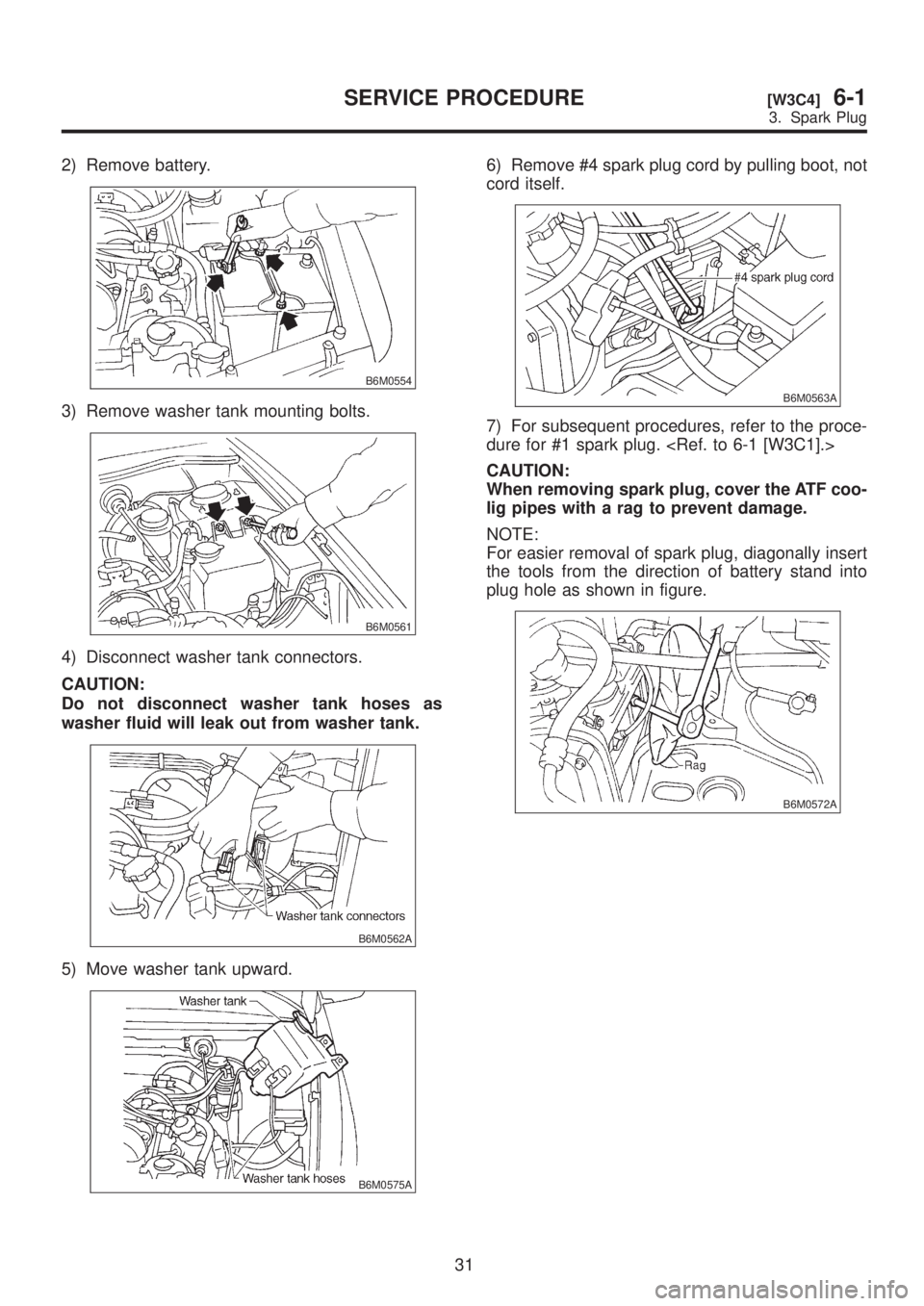
3) Remove washer tank mounting bolts.
B6M0561
4) Disconnect washer tank connectors.
CAUTION:
Do not disconnect washer tank hoses as
washer fluid will leak out from washer tank.
B6M0562A
5) Move washer tank upward.
B6M0575A
6) Remove #4 spark plug cord by pulling boot, not
cord itself.
B6M0563A
7) For subsequent procedures, refer to the proce-
dure for #1 spark plug.
CAUTION:
When removing spark plug, cover the ATF coo-
lig pipes with a rag to prevent damage.
NOTE:
For easier removal of spark plug, diagonally insert
the tools from the direction of battery stand into
plug hole as shown in figure.
B6M0572A
31
[W3C4]6-1SERVICE PROCEDURE
3. Spark Plug
Page 1214 of 1456
D: INSTALLATION (2500 cc
OUTBACK MODEL)
1. #1 SPARK PLUG
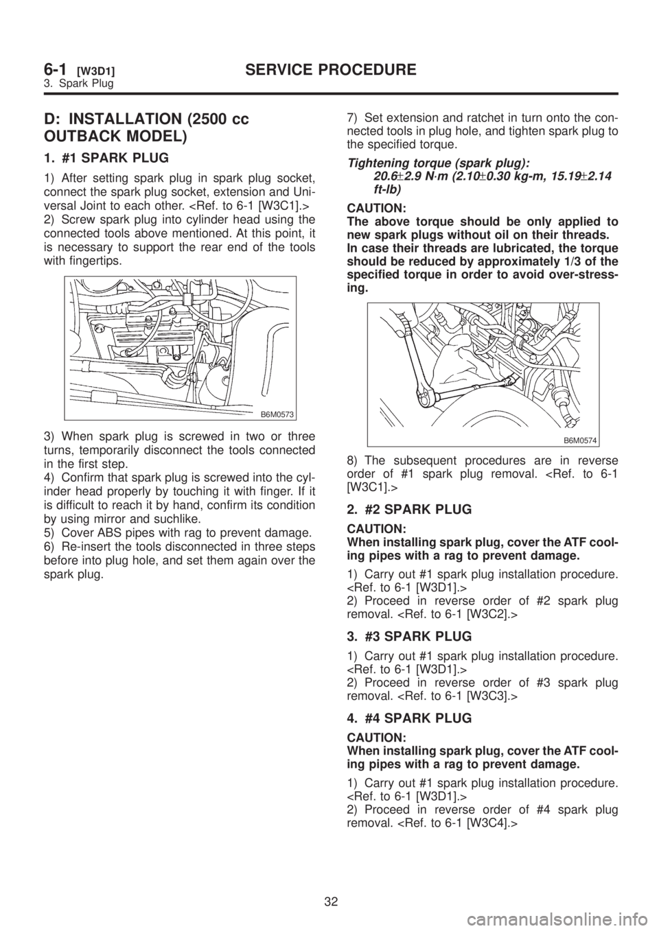
1) After setting spark plug in spark plug socket,
connect the spark plug socket, extension and Uni-
versal Joint to each other.
2) Screw spark plug into cylinder head using the
connected tools above mentioned. At this point, it
is necessary to support the rear end of the tools
with fingertips.
B6M0573
3) When spark plug is screwed in two or three
turns, temporarily disconnect the tools connected
in the first step.
4) Confirm that spark plug is screwed into the cyl-
inder head properly by touching it with finger. If it
is difficult to reach it by hand, confirm its condition
by using mirror and suchlike.
5) Cover ABS pipes with rag to prevent damage.
6) Re-insert the tools disconnected in three steps
before into plug hole, and set them again over the
spark plug.7) Set extension and ratchet in turn onto the con-
nected tools in plug hole, and tighten spark plug to
the specified torque.
Tightening torque (spark plug):
20.6
±2.9 N´m (2.10±0.30 kg-m, 15.19±2.14
ft-lb)
CAUTION:
The above torque should be only applied to
new spark plugs without oil on their threads.
In case their threads are lubricated, the torque
should be reduced by approximately 1/3 of the
specified torque in order to avoid over-stress-
ing.
B6M0574
8) The subsequent procedures are in reverse
order of #1 spark plug removal.
2. #2 SPARK PLUG
CAUTION:
When installing spark plug, cover the ATF cool-
ing pipes with a rag to prevent damage.
1) Carry out #1 spark plug installation procedure.
2) Proceed in reverse order of #2 spark plug
removal.
3. #3 SPARK PLUG
1) Carry out #1 spark plug installation procedure.
2) Proceed in reverse order of #3 spark plug
removal.
4. #4 SPARK PLUG
CAUTION:
When installing spark plug, cover the ATF cool-
ing pipes with a rag to prevent damage.
1) Carry out #1 spark plug installation procedure.
2) Proceed in reverse order of #4 spark plug
removal.
32
6-1[W3D1]SERVICE PROCEDURE
3. Spark Plug
Page 1215 of 1456
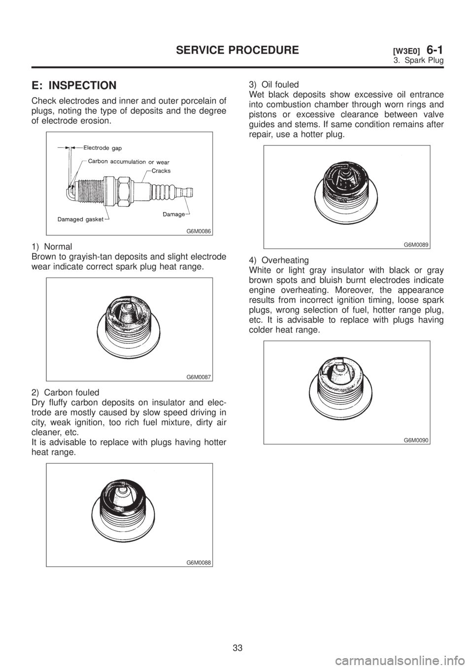
E: INSPECTION
Check electrodes and inner and outer porcelain of
plugs, noting the type of deposits and the degree
of electrode erosion.
G6M0086
1) Normal
Brown to grayish-tan deposits and slight electrode
wear indicate correct spark plug heat range.
G6M0087
2) Carbon fouled
Dry fluffy carbon deposits on insulator and elec-
trode are mostly caused by slow speed driving in
city, weak ignition, too rich fuel mixture, dirty air
cleaner, etc.
It is advisable to replace with plugs having hotter
heat range.
G6M0088
3) Oil fouled
Wet black deposits show excessive oil entrance
into combustion chamber through worn rings and
pistons or excessive clearance between valve
guides and stems. If same condition remains after
repair, use a hotter plug.
G6M0089
4) Overheating
White or light gray insulator with black or gray
brown spots and bluish burnt electrodes indicate
engine overheating. Moreover, the appearance
results from incorrect ignition timing, loose spark
plugs, wrong selection of fuel, hotter range plug,
etc. It is advisable to replace with plugs having
colder heat range.
G6M0090
33
[W3E0]6-1SERVICE PROCEDURE
3. Spark Plug
Page 1216 of 1456
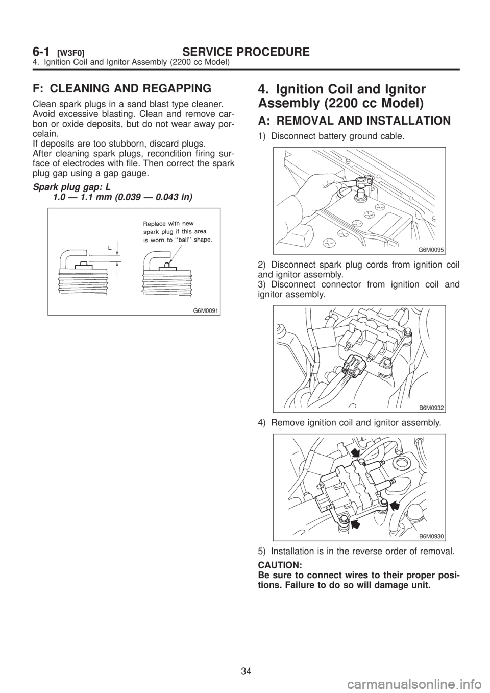
F: CLEANING AND REGAPPING
Clean spark plugs in a sand blast type cleaner.
Avoid excessive blasting. Clean and remove car-
bon or oxide deposits, but do not wear away por-
celain.
If deposits are too stubborn, discard plugs.
After cleaning spark plugs, recondition firing sur-
face of electrodes with file. Then correct the spark
plug gap using a gap gauge.
Spark plug gap: L
1.0 Ð 1.1 mm (0.039 Ð 0.043 in)
G6M0091
4. Ignition Coil and Ignitor
Assembly (2200 cc Model)
A: REMOVAL AND INSTALLATION
1) Disconnect battery ground cable.
G6M0095
2) Disconnect spark plug cords from ignition coil
and ignitor assembly.
3) Disconnect connector from ignition coil and
ignitor assembly.
B6M0932
4) Remove ignition coil and ignitor assembly.
B6M0930
5) Installation is in the reverse order of removal.
CAUTION:
Be sure to connect wires to their proper posi-
tions. Failure to do so will damage unit.
34
6-1[W3F0]SERVICE PROCEDURE
4. Ignition Coil and Ignitor Assembly (2200 cc Model)
Page 1217 of 1456
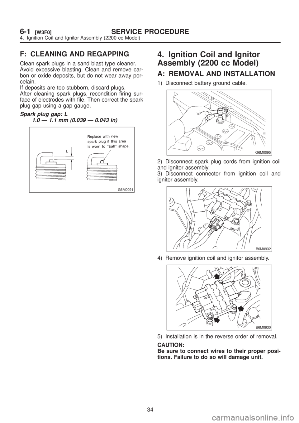
F: CLEANING AND REGAPPING
Clean spark plugs in a sand blast type cleaner.
Avoid excessive blasting. Clean and remove car-
bon or oxide deposits, but do not wear away por-
celain.
If deposits are too stubborn, discard plugs.
After cleaning spark plugs, recondition firing sur-
face of electrodes with file. Then correct the spark
plug gap using a gap gauge.
Spark plug gap: L
1.0 Ð 1.1 mm (0.039 Ð 0.043 in)
G6M0091
4. Ignition Coil and Ignitor
Assembly (2200 cc Model)
A: REMOVAL AND INSTALLATION
1) Disconnect battery ground cable.
G6M0095
2) Disconnect spark plug cords from ignition coil
and ignitor assembly.
3) Disconnect connector from ignition coil and
ignitor assembly.
B6M0932
4) Remove ignition coil and ignitor assembly.
B6M0930
5) Installation is in the reverse order of removal.
CAUTION:
Be sure to connect wires to their proper posi-
tions. Failure to do so will damage unit.
34
6-1[W3F0]SERVICE PROCEDURE
4. Ignition Coil and Ignitor Assembly (2200 cc Model)
Page 1218 of 1456
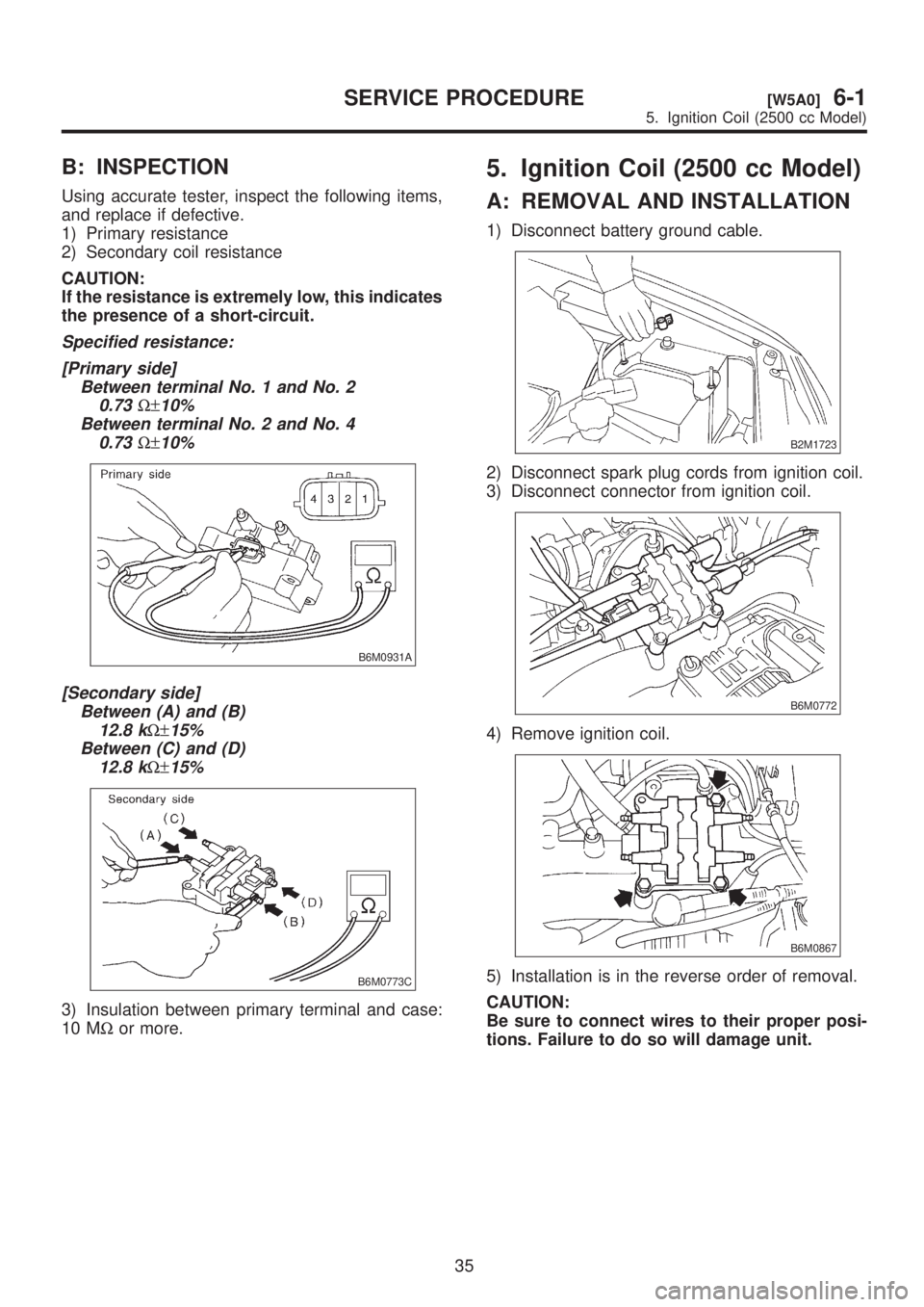
B: INSPECTION
Using accurate tester, inspect the following items,
and replace if defective.
1) Primary resistance
2) Secondary coil resistance
CAUTION:
If the resistance is extremely low, this indicates
the presence of a short-circuit.
Specified resistance:
[Primary side]
Between terminal No. 1 and No. 2
0.73
W±10%
Between terminal No. 2 and No. 4
0.73
W±10%
B6M0931A
[Secondary side]
Between (A) and (B)
12.8 k
W±15%
Between (C) and (D)
12.8 k
W±15%
B6M0773C
3) Insulation between primary terminal and case:
10 MWor more.
5. Ignition Coil (2500 cc Model)
A: REMOVAL AND INSTALLATION
1) Disconnect battery ground cable.
B2M1723
2) Disconnect spark plug cords from ignition coil.
3) Disconnect connector from ignition coil.
B6M0772
4) Remove ignition coil.
B6M0867
5) Installation is in the reverse order of removal.
CAUTION:
Be sure to connect wires to their proper posi-
tions. Failure to do so will damage unit.
35
[W5A0]6-1SERVICE PROCEDURE
5. Ignition Coil (2500 cc Model)
Page 1219 of 1456
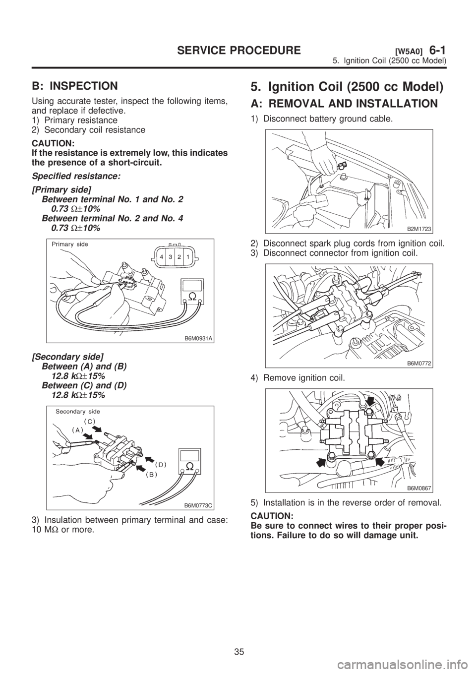
B: INSPECTION
Using accurate tester, inspect the following items,
and replace if defective.
1) Primary resistance
2) Secondary coil resistance
CAUTION:
If the resistance is extremely low, this indicates
the presence of a short-circuit.
Specified resistance:
[Primary side]
Between terminal No. 1 and No. 2
0.73
W±10%
Between terminal No. 2 and No. 4
0.73
W±10%
B6M0931A
[Secondary side]
Between (A) and (B)
12.8 k
W±15%
Between (C) and (D)
12.8 k
W±15%
B6M0773C
3) Insulation between primary terminal and case:
10 MWor more.
5. Ignition Coil (2500 cc Model)
A: REMOVAL AND INSTALLATION
1) Disconnect battery ground cable.
B2M1723
2) Disconnect spark plug cords from ignition coil.
3) Disconnect connector from ignition coil.
B6M0772
4) Remove ignition coil.
B6M0867
5) Installation is in the reverse order of removal.
CAUTION:
Be sure to connect wires to their proper posi-
tions. Failure to do so will damage unit.
35
[W5A0]6-1SERVICE PROCEDURE
5. Ignition Coil (2500 cc Model)
Page 1220 of 1456
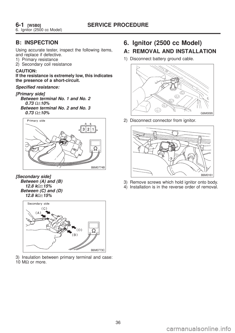
B: INSPECTION
Using accurate tester, inspect the following items,
and replace if defective.
1) Primary resistance
2) Secondary coil resistance
CAUTION:
If the resistance is extremely low, this indicates
the presence of a short-circuit.
Specified resistance:
[Primary side]
Between terminal No. 1 and No. 2
0.73
W±10%
Between terminal No. 2 and No. 3
0.73
W±10%
B6M0774B
[Secondary side]
Between (A) and (B)
12.8 k
W±15%
Between (C) and (D)
12.8 k
W±15%
B6M0773C
3) Insulation between primary terminal and case:
10 MWor more.
6. Ignitor (2500 cc Model)
A: REMOVAL AND INSTALLATION
1) Disconnect battery ground cable.
G6M0095
2) Disconnect connector from ignitor.
B6M0161
3) Remove screws which hold ignitor onto body.
4) Installation is in the reverse order of removal.
36
6-1[W5B0]SERVICE PROCEDURE
6. Ignitor (2500 cc Model)