SUBARU LEGACY 1999 Service Repair Manual
Manufacturer: SUBARU, Model Year: 1999, Model line: LEGACY, Model: SUBARU LEGACY 1999Pages: 1456, PDF Size: 59.93 MB
Page 1251 of 1456
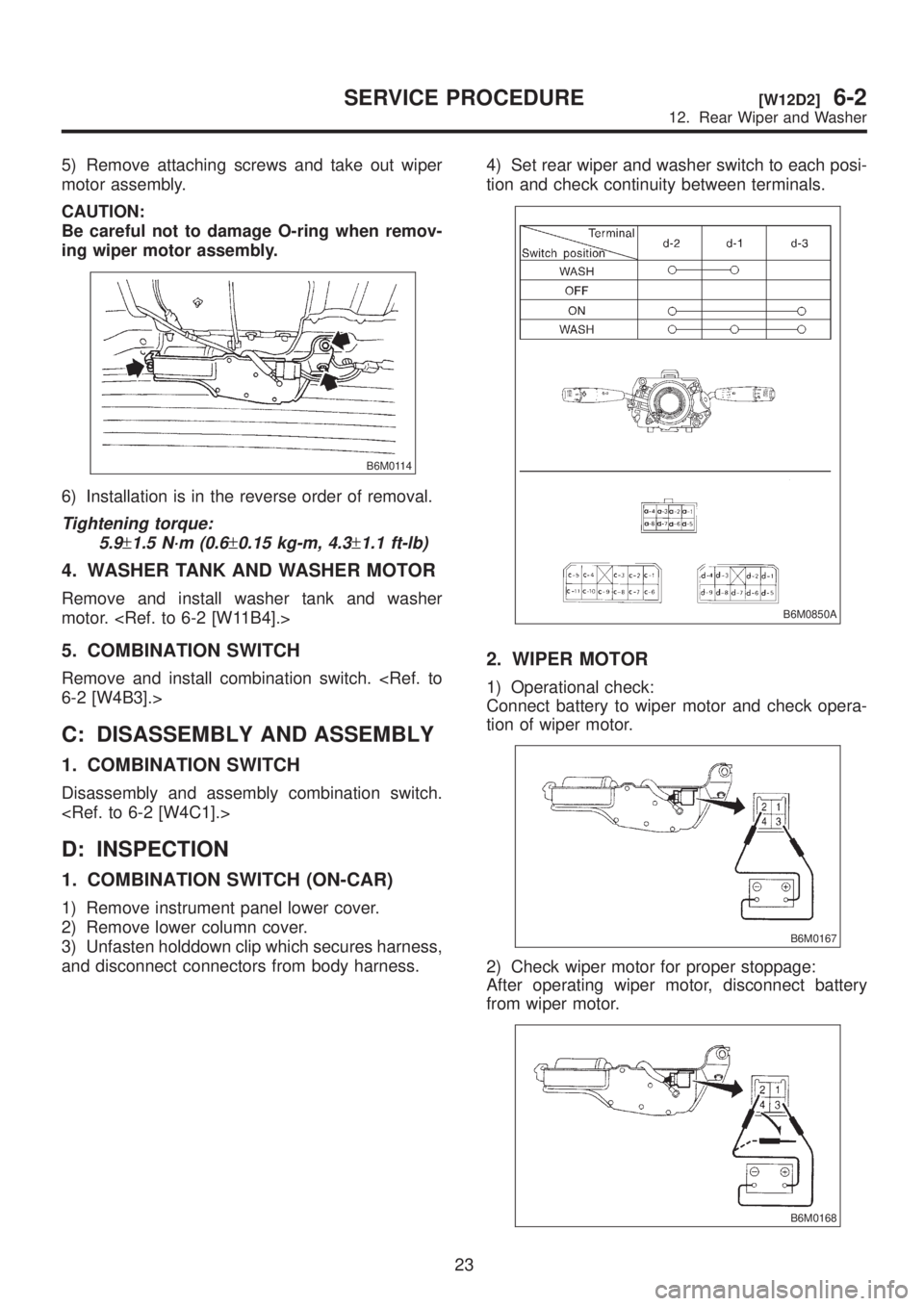
5) Remove attaching screws and take out wiper
motor assembly.
CAUTION:
Be careful not to damage O-ring when remov-
ing wiper motor assembly.
B6M0114
6) Installation is in the reverse order of removal.
Tightening torque:
5.9
±1.5 N´m (0.6±0.15 kg-m, 4.3±1.1 ft-lb)
4. WASHER TANK AND WASHER MOTOR
Remove and install washer tank and washer
motor.
5. COMBINATION SWITCH
Remove and install combination switch.
C: DISASSEMBLY AND ASSEMBLY
1. COMBINATION SWITCH
Disassembly and assembly combination switch.
D: INSPECTION
1. COMBINATION SWITCH (ON-CAR)
1) Remove instrument panel lower cover.
2) Remove lower column cover.
3) Unfasten holddown clip which secures harness,
and disconnect connectors from body harness.4) Set rear wiper and washer switch to each posi-
tion and check continuity between terminals.
B6M0850A
2. WIPER MOTOR
1) Operational check:
Connect battery to wiper motor and check opera-
tion of wiper motor.
B6M0167
2) Check wiper motor for proper stoppage:
After operating wiper motor, disconnect battery
from wiper motor.
B6M0168
23
[W12D2]6-2SERVICE PROCEDURE
12. Rear Wiper and Washer
Page 1252 of 1456
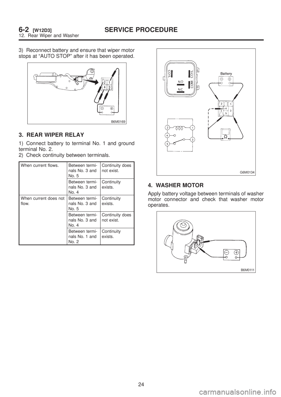
3) Reconnect battery and ensure that wiper motor
stops at ªAUTO STOPº after it has been operated.
B6M0169
3. REAR WIPER RELAY
1) Connect battery to terminal No. 1 and ground
terminal No. 2.
2) Check continuity between terminals.
When current flows. Between termi-
nals No. 3 and
No. 5Continuity does
not exist.
Between termi-
nals No. 3 and
No. 4Continuity
exists.
When current does not
flow.Between termi-
nals No. 3 and
No. 5Continuity
exists.
Between termi-
nals No. 3 and
No. 4Continuity does
not exist.
Between termi-
nals No. 1 and
No. 2Continuity
exists.
G6M0134
4. WASHER MOTOR
Apply battery voltage between terminals of washer
motor connector and check that washer motor
operates.
B6M0111
24
6-2[W12D3]SERVICE PROCEDURE
12. Rear Wiper and Washer
Page 1253 of 1456
13. Rear Window Defogger
A: REMOVAL AND INSTALLATION
1. DEFOGGER SWITCH
1) Remove screws which secure meter visor.
2) Remove meter visor from instrument panel
while disconnecting connectors.
3) Remove rear window defogger switch from
meter visor.
4) Installation is in the reverse order of removal.
B: INSPECTION
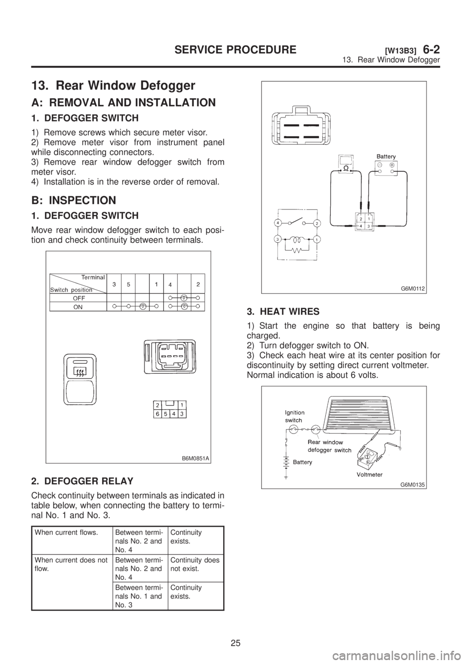
1. DEFOGGER SWITCH
Move rear window defogger switch to each posi-
tion and check continuity between terminals.
B6M0851A
2. DEFOGGER RELAY
Check continuity between terminals as indicated in
table below, when connecting the battery to termi-
nal No. 1 and No. 3.
When current flows. Between termi-
nals No. 2 and
No. 4Continuity
exists.
When current does not
flow.Between termi-
nals No. 2 and
No. 4Continuity does
not exist.
Between termi-
nals No. 1 and
No. 3Continuity
exists.
G6M0112
3. HEAT WIRES
1) Start the engine so that battery is being
charged.
2) Turn defogger switch to ON.
3) Check each heat wire at its center position for
discontinuity by setting direct current voltmeter.
Normal indication is about 6 volts.
G6M0135
25
[W13B3]6-2SERVICE PROCEDURE
13. Rear Window Defogger
Page 1254 of 1456
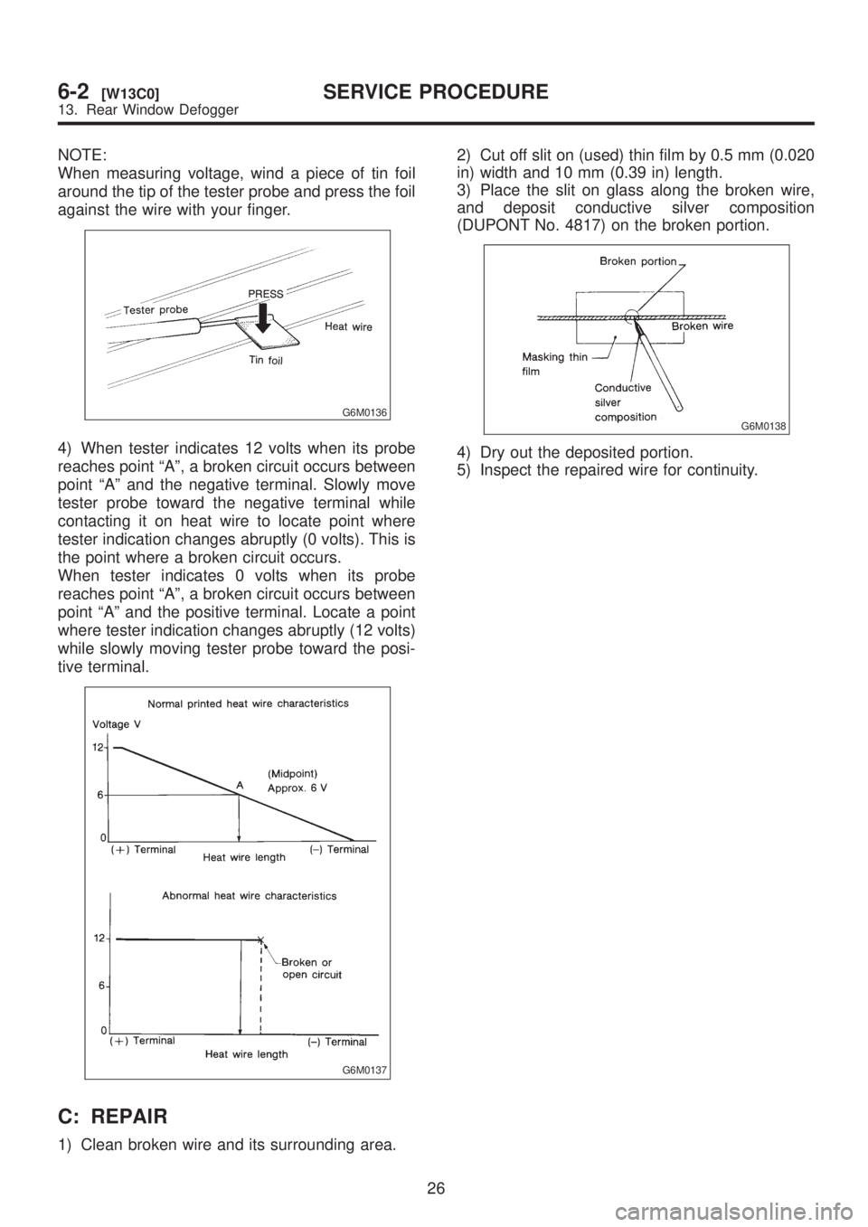
NOTE:
When measuring voltage, wind a piece of tin foil
around the tip of the tester probe and press the foil
against the wire with your finger.
G6M0136
4) When tester indicates 12 volts when its probe
reaches point ªAº, a broken circuit occurs between
point ªAº and the negative terminal. Slowly move
tester probe toward the negative terminal while
contacting it on heat wire to locate point where
tester indication changes abruptly (0 volts). This is
the point where a broken circuit occurs.
When tester indicates 0 volts when its probe
reaches point ªAº, a broken circuit occurs between
point ªAº and the positive terminal. Locate a point
where tester indication changes abruptly (12 volts)
while slowly moving tester probe toward the posi-
tive terminal.
G6M0137
C: REPAIR
1) Clean broken wire and its surrounding area.2) Cut off slit on (used) thin film by 0.5 mm (0.020
in) width and 10 mm (0.39 in) length.
3) Place the slit on glass along the broken wire,
and deposit conductive silver composition
(DUPONT No. 4817) on the broken portion.
G6M0138
4) Dry out the deposited portion.
5) Inspect the repaired wire for continuity.
26
6-2[W13C0]SERVICE PROCEDURE
13. Rear Window Defogger
Page 1255 of 1456
14. Combination Meter
A: REMOVAL AND INSTALLATION
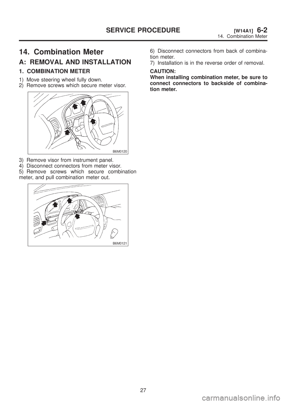
1. COMBINATION METER
1) Move steering wheel fully down.
2) Remove screws which secure meter visor.
B6M0120
3) Remove visor from instrument panel.
4) Disconnect connectors from meter visor.
5) Remove screws which secure combination
meter, and pull combination meter out.
B6M0121
6) Disconnect connectors from back of combina-
tion meter.
7) Installation is in the reverse order of removal.
CAUTION:
When installing combination meter, be sure to
connect connectors to backside of combina-
tion meter.
27
[W14A1]6-2SERVICE PROCEDURE
14. Combination Meter
Page 1256 of 1456
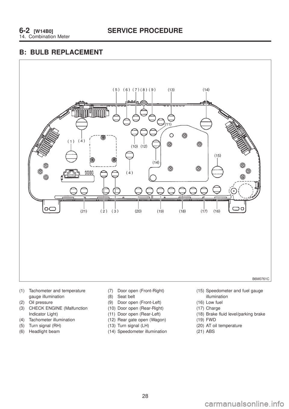
B: BULB REPLACEMENT
B6M0761C
(1) Tachometer and temperature
gauge illumination
(2) Oil pressure
(3) CHECK ENGINE (Malfunction
Indicator Light)
(4) Tachometer illumination
(5) Turn signal (RH)
(6) Headlight beam(7) Door open (Front-Right)
(8) Seat belt
(9) Door open (Front-Left)
(10) Door open (Rear-Right)
(11) Door open (Rear-Left)
(12) Rear gate open (Wagon)
(13) Turn signal (LH)
(14) Speedometer illumination(15) Speedometer and fuel gauge
illumination
(16) Low fuel
(17) Charge
(18) Brake fluid level/parking brake
(19) FWD
(20) AT oil temperature
(21) ABS
28
6-2[W14B0]SERVICE PROCEDURE
14. Combination Meter
Page 1257 of 1456
15. Vehicle Speed Sensor 2
A: GENERAL PRECAUTIONS
(1) Be careful not to drop or bump sensor as this
may break built-in magnet.
(2) Drive key is designed to separate from vehicle
speed sensor 2. Be careful not to lose it or forget
to install.
(3) Vehicle speed sensor 2 is installed in part
(which contains bearings, etc., finished to a high
degree of accuracy). Do not allow foreign matter
(filings, sand, etc.) to get into it.
(4) When checking output of vehicle speed sensor
2 as a single unit, ensure test leads are connected
to their correct terminals. Failure to do this may
damage internal IC.
(5) Discard vehicle speed sensor 2 after removal;
replace with new one.
B: REMOVAL
CAUTION:
IBe careful when removing vehicle speed
sensor 2 immediately after driving vehicle for a
while, as temperature around it is high.
IBefore removing vehicle speed sensor 2,
clean dirt, etc. from surrounding areas. Take
care not to allow foreign matter to get into
mounting hole.
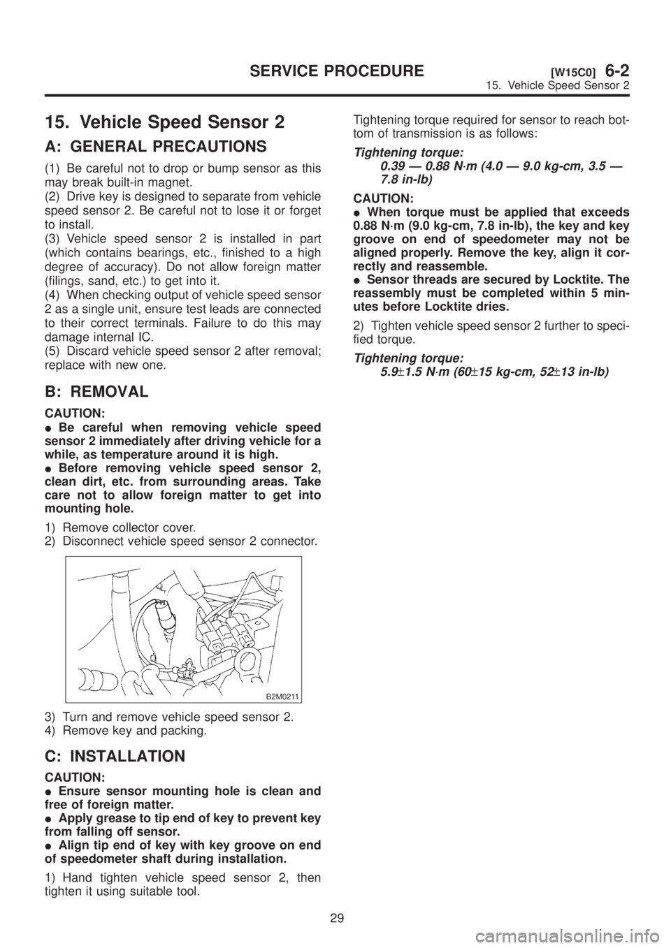
1) Remove collector cover.
2) Disconnect vehicle speed sensor 2 connector.
B2M0211
3) Turn and remove vehicle speed sensor 2.
4) Remove key and packing.
C: INSTALLATION
CAUTION:
IEnsure sensor mounting hole is clean and
free of foreign matter.
IApply grease to tip end of key to prevent key
from falling off sensor.
IAlign tip end of key with key groove on end
of speedometer shaft during installation.
1) Hand tighten vehicle speed sensor 2, then
tighten it using suitable tool.Tightening torque required for sensor to reach bot-
tom of transmission is as follows:
Tightening torque:
0.39 Ð 0.88 N´m (4.0 Ð 9.0 kg-cm, 3.5 Ð
7.8 in-lb)
CAUTION:
IWhen torque must be applied that exceeds
0.88 N´m (9.0 kg-cm, 7.8 in-lb), the key and key
groove on end of speedometer may not be
aligned properly. Remove the key, align it cor-
rectly and reassemble.
ISensor threads are secured by Locktite. The
reassembly must be completed within 5 min-
utes before Locktite dries.
2) Tighten vehicle speed sensor 2 further to speci-
fied torque.
Tightening torque:
5.9
±1.5 N´m (60±15 kg-cm, 52±13 in-lb)
29
[W15C0]6-2SERVICE PROCEDURE
15. Vehicle Speed Sensor 2
Page 1258 of 1456
16. Horn and Cigarette Lighter
A: REMOVAL AND INSTALLATION
1. HORN
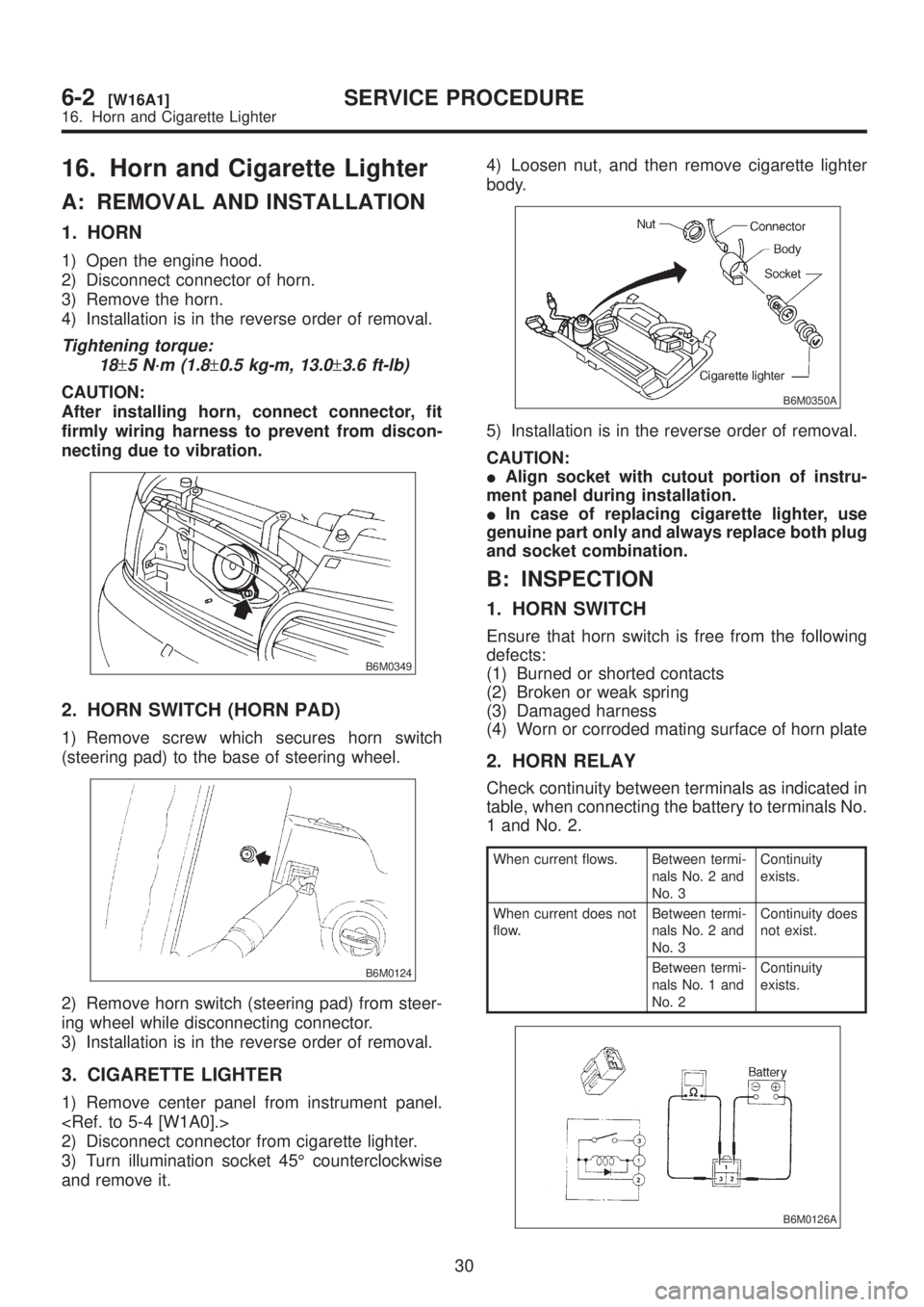
1) Open the engine hood.
2) Disconnect connector of horn.
3) Remove the horn.
4) Installation is in the reverse order of removal.
Tightening torque:
18
±5 N´m (1.8±0.5 kg-m, 13.0±3.6 ft-lb)
CAUTION:
After installing horn, connect connector, fit
firmly wiring harness to prevent from discon-
necting due to vibration.
B6M0349
2. HORN SWITCH (HORN PAD)
1) Remove screw which secures horn switch
(steering pad) to the base of steering wheel.
B6M0124
2) Remove horn switch (steering pad) from steer-
ing wheel while disconnecting connector.
3) Installation is in the reverse order of removal.
3. CIGARETTE LIGHTER
1) Remove center panel from instrument panel.
2) Disconnect connector from cigarette lighter.
3) Turn illumination socket 45É counterclockwise
and remove it.4) Loosen nut, and then remove cigarette lighter
body.
B6M0350A
5) Installation is in the reverse order of removal.
CAUTION:
IAlign socket with cutout portion of instru-
ment panel during installation.
IIn case of replacing cigarette lighter, use
genuine part only and always replace both plug
and socket combination.
B: INSPECTION
1. HORN SWITCH
Ensure that horn switch is free from the following
defects:
(1) Burned or shorted contacts
(2) Broken or weak spring
(3) Damaged harness
(4) Worn or corroded mating surface of horn plate
2. HORN RELAY
Check continuity between terminals as indicated in
table, when connecting the battery to terminals No.
1 and No. 2.
When current flows. Between termi-
nals No. 2 and
No. 3Continuity
exists.
When current does not
flow.Between termi-
nals No. 2 and
No. 3Continuity does
not exist.
Between termi-
nals No. 1 and
No. 2Continuity
exists.
B6M0126A
30
6-2[W16A1]SERVICE PROCEDURE
16. Horn and Cigarette Lighter
Page 1259 of 1456
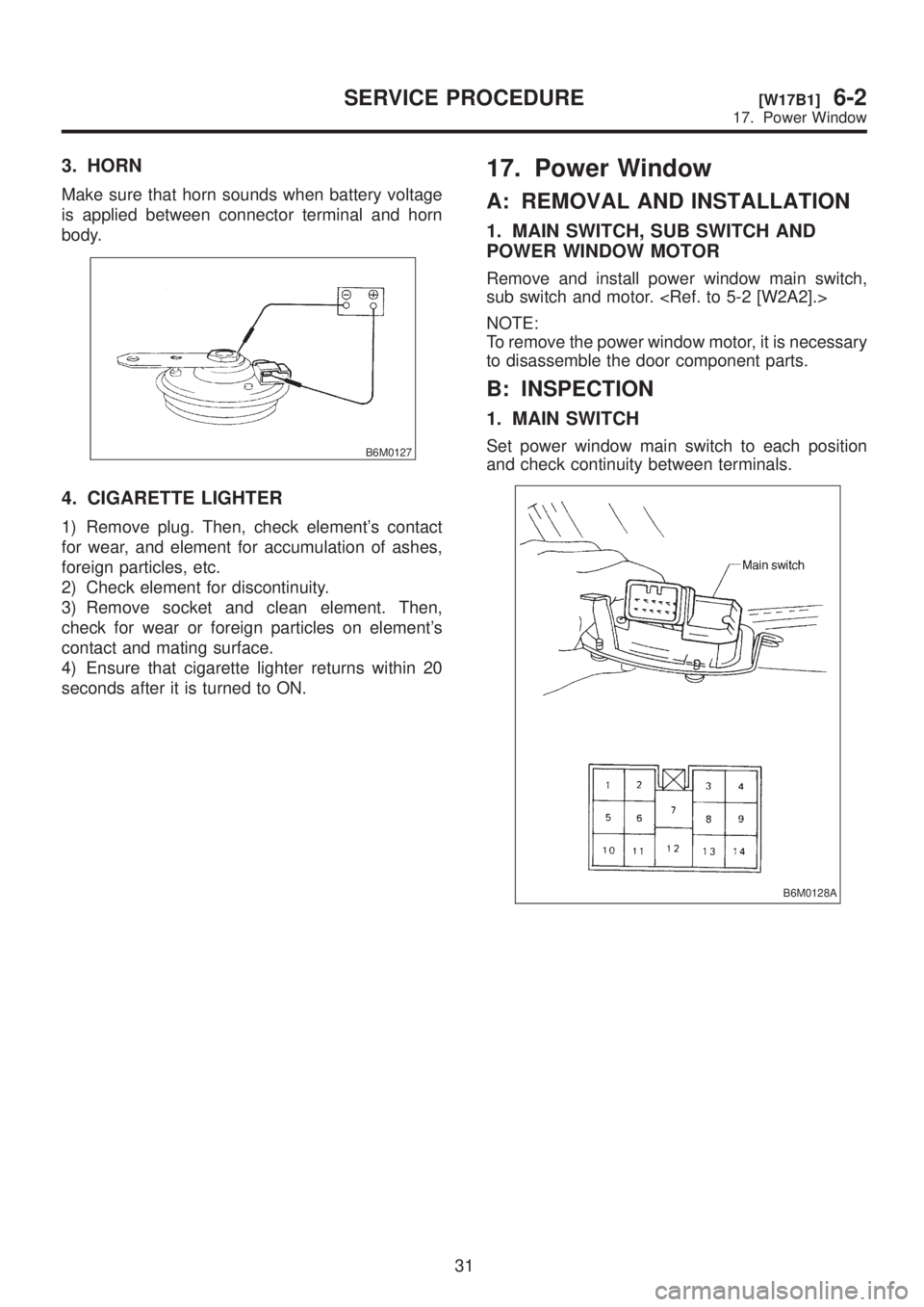
3. HORN
Make sure that horn sounds when battery voltage
is applied between connector terminal and horn
body.
B6M0127
4. CIGARETTE LIGHTER
1) Remove plug. Then, check element's contact
for wear, and element for accumulation of ashes,
foreign particles, etc.
2) Check element for discontinuity.
3) Remove socket and clean element. Then,
check for wear or foreign particles on element's
contact and mating surface.
4) Ensure that cigarette lighter returns within 20
seconds after it is turned to ON.
17. Power Window
A: REMOVAL AND INSTALLATION
1. MAIN SWITCH, SUB SWITCH AND
POWER WINDOW MOTOR
Remove and install power window main switch,
sub switch and motor.
NOTE:
To remove the power window motor, it is necessary
to disassemble the door component parts.
B: INSPECTION
1. MAIN SWITCH
Set power window main switch to each position
and check continuity between terminals.
B6M0128A
31
[W17B1]6-2SERVICE PROCEDURE
17. Power Window
Page 1260 of 1456
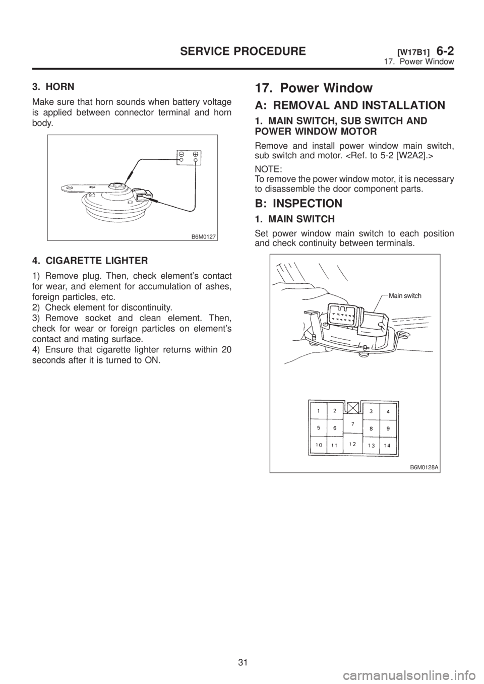
3. HORN
Make sure that horn sounds when battery voltage
is applied between connector terminal and horn
body.
B6M0127
4. CIGARETTE LIGHTER
1) Remove plug. Then, check element's contact
for wear, and element for accumulation of ashes,
foreign particles, etc.
2) Check element for discontinuity.
3) Remove socket and clean element. Then,
check for wear or foreign particles on element's
contact and mating surface.
4) Ensure that cigarette lighter returns within 20
seconds after it is turned to ON.
17. Power Window
A: REMOVAL AND INSTALLATION
1. MAIN SWITCH, SUB SWITCH AND
POWER WINDOW MOTOR
Remove and install power window main switch,
sub switch and motor.
NOTE:
To remove the power window motor, it is necessary
to disassemble the door component parts.
B: INSPECTION
1. MAIN SWITCH
Set power window main switch to each position
and check continuity between terminals.
B6M0128A
31
[W17B1]6-2SERVICE PROCEDURE
17. Power Window