SUBARU LEGACY 1999 Service Repair Manual
Manufacturer: SUBARU, Model Year: 1999, Model line: LEGACY, Model: SUBARU LEGACY 1999Pages: 1456, PDF Size: 59.93 MB
Page 1221 of 1456
B: INSPECTION
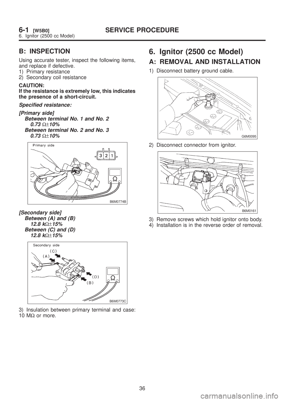
Using accurate tester, inspect the following items,
and replace if defective.
1) Primary resistance
2) Secondary coil resistance
CAUTION:
If the resistance is extremely low, this indicates
the presence of a short-circuit.
Specified resistance:
[Primary side]
Between terminal No. 1 and No. 2
0.73
W±10%
Between terminal No. 2 and No. 3
0.73
W±10%
B6M0774B
[Secondary side]
Between (A) and (B)
12.8 k
W±15%
Between (C) and (D)
12.8 k
W±15%
B6M0773C
3) Insulation between primary terminal and case:
10 MWor more.
6. Ignitor (2500 cc Model)
A: REMOVAL AND INSTALLATION
1) Disconnect battery ground cable.
G6M0095
2) Disconnect connector from ignitor.
B6M0161
3) Remove screws which hold ignitor onto body.
4) Installation is in the reverse order of removal.
36
6-1[W5B0]SERVICE PROCEDURE
6. Ignitor (2500 cc Model)
Page 1222 of 1456
7. Spark Plug Cord
A: INSPECTION
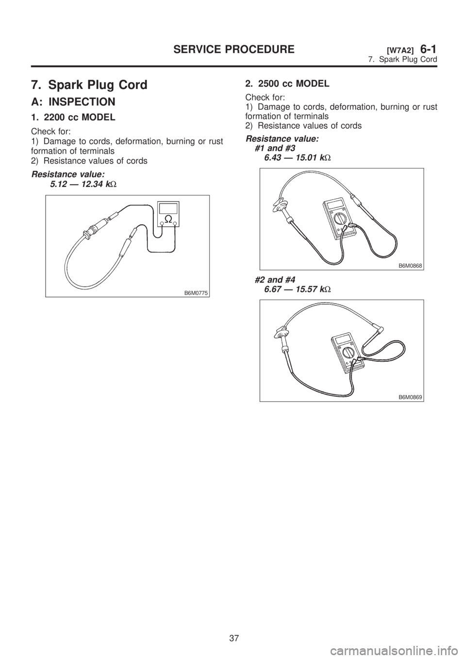
1. 2200 cc MODEL
Check for:
1) Damage to cords, deformation, burning or rust
formation of terminals
2) Resistance values of cords
Resistance value:
5.12 Ð 12.34 k
W
B6M0775
2. 2500 cc MODEL
Check for:
1) Damage to cords, deformation, burning or rust
formation of terminals
2) Resistance values of cords
Resistance value:
#1 and #3
6.43 Ð 15.01 k
W
B6M0868
#2 and #4
6.67 Ð 15.57 k
W
B6M0869
37
[W7A2]6-1SERVICE PROCEDURE
7. Spark Plug Cord
Page 1223 of 1456
1. Starter
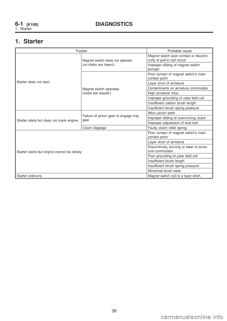
Trouble Probable cause
Starter does not start.Magnet switch does not operate.
(no clicks are heard.)Magnet switch poor contact or disconti-
nuity of pull-in coil circuit
Improper sliding of magnet switch
plunger
Magnet switch operates.
(clicks are issued.)Poor contact of magnet switch's main
contact point
Layer short of armature
Contaminants on armature commutator
High armature mica
Improper grounding of yoke field coil
Insufficient carbon brush length
Insufficient brush spring pressure
Starter starts but does not crank engine.Failure of pinion gear to engage ring
gearWorn pinion teeth
Improper sliding of overrunning clutch
Improper adjustment of stud bolt
Clutch slippage Faulty clutch roller spring
Starter starts but engine cranks too slowly.Poor contact of magnet switch's main
contact point
Layer short of armature
Discontinuity, burning or wear of arma-
ture commutator
Poor grounding of yoke field coil
Insufficient brush length
Insufficient brush spring pressure
Abnormal brush wear
Starter overruns. Magnet switch coil is a layer short.
38
6-1[K100]DIAGNOSTICS
1. Starter
Page 1224 of 1456
![SUBARU LEGACY 1999 Service Repair Manual 2. Generator
B6M0771
39
[K200]6-1DIAGNOSTICS
2. Generator SUBARU LEGACY 1999 Service Repair Manual 2. Generator
B6M0771
39
[K200]6-1DIAGNOSTICS
2. Generator](/img/17/57435/w960_57435-1223.png)
2. Generator
B6M0771
39
[K200]6-1DIAGNOSTICS
2. Generator
Page 1225 of 1456

MEMO:
40
6-1DIAGNOSTICS
Page 1226 of 1456
1. Body Electrical
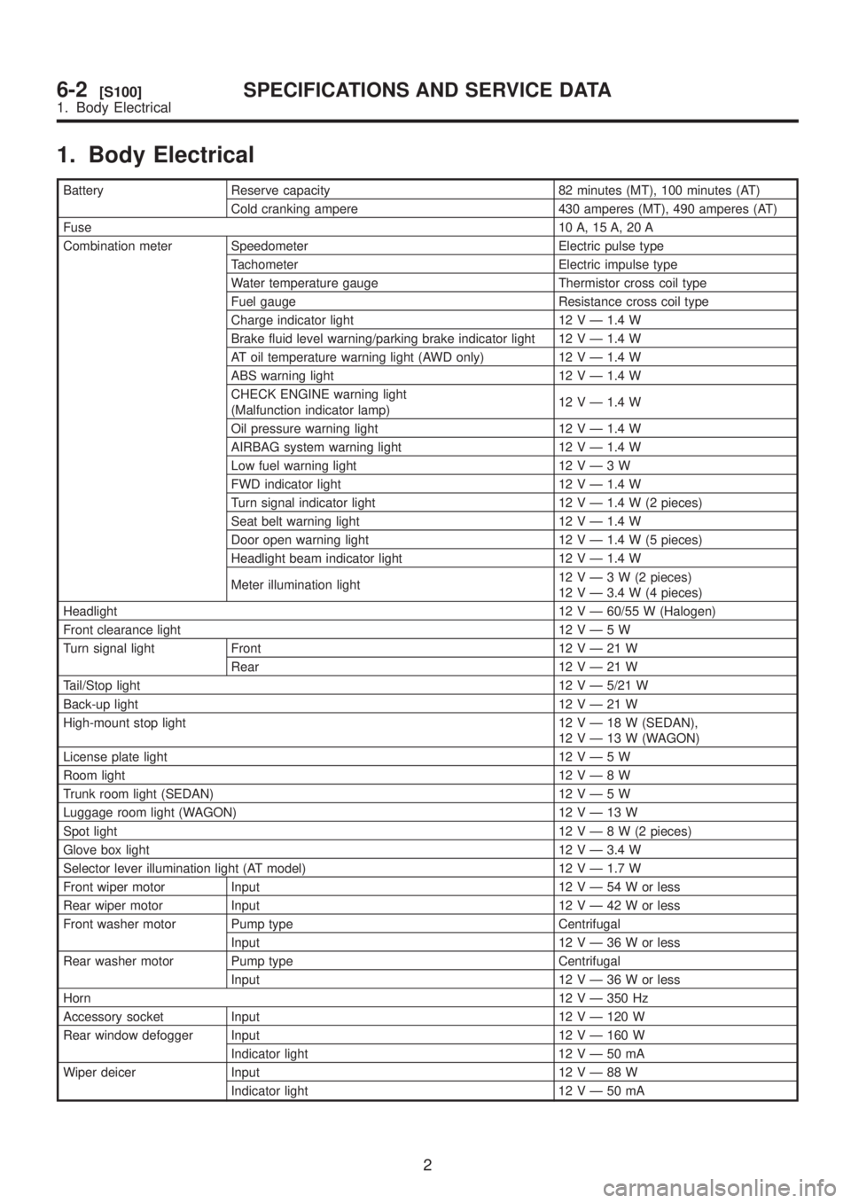
Battery Reserve capacity 82 minutes (MT), 100 minutes (AT)
Cold cranking ampere 430 amperes (MT), 490 amperes (AT)
Fuse10 A, 15 A, 20 A
Combination meter Speedometer Electric pulse type
Tachometer Electric impulse type
Water temperature gauge Thermistor cross coil type
Fuel gauge Resistance cross coil type
Charge indicator light 12 V Ð 1.4 W
Brake fluid level warning/parking brake indicator light 12 V Ð 1.4 W
AT oil temperature warning light (AWD only) 12 V Ð 1.4 W
ABS warning light 12 V Ð 1.4 W
CHECK ENGINE warning light
(Malfunction indicator lamp)12 V Ð 1.4 W
Oil pressure warning light 12 V Ð 1.4 W
AIRBAG system warning light 12 V Ð 1.4 W
Low fuel warning light 12VÐ3W
FWD indicator light 12 V Ð 1.4 W
Turn signal indicator light 12 V Ð 1.4 W (2 pieces)
Seat belt warning light 12 V Ð 1.4 W
Door open warning light 12 V Ð 1.4 W (5 pieces)
Headlight beam indicator light 12 V Ð 1.4 W
Meter illumination light12VÐ3W(2pieces)
12 V Ð 3.4 W (4 pieces)
Headlight12 V Ð 60/55 W (Halogen)
Front clearance light 12VÐ5W
Turn signal light Front 12VÐ21W
Rear 12VÐ21W
Tail/Stop light12 V Ð 5/21 W
Back-up light12VÐ21W
High-mount stop light 12VÐ18W(SEDAN),
12VÐ13W(WAGON)
License plate light 12VÐ5W
Room light12VÐ8W
Trunk room light (SEDAN) 12VÐ5W
Luggage room light (WAGON) 12VÐ13W
Spot light12VÐ8W(2pieces)
Glove box light 12 V Ð 3.4 W
Selector lever illumination light (AT model) 12 V Ð 1.7 W
Front wiper motor Input 12VÐ54Worless
Rear wiper motor Input 12VÐ42Worless
Front washer motor Pump type Centrifugal
Input 12VÐ36Worless
Rear washer motor Pump type Centrifugal
Input 12VÐ36Worless
Horn12 V Ð 350 Hz
Accessory socket Input 12 V Ð 120 W
Rear window defogger Input 12 V Ð 160 W
Indicator light 12VÐ50mA
Wiper deicer Input 12VÐ88W
Indicator light 12VÐ50mA
2
6-2[S100]SPECIFICATIONS AND SERVICE DATA
1. Body Electrical
Page 1227 of 1456
1. Precaution
IBefore disassembling or reassembling parts,
always disconnect battery ground cable. When
repairing radio, control modules, etc. which are
provided with memory functions, record
memory contents before disconnecting battery
ground cable. Otherwise, these contents are
cancelled upon disconnection.
IReassemble parts in reverse order of disas-
sembly procedure unless otherwise indicated.
IAdjust parts to specifications contained in
this manual if so designated.
IConnect connectors and hoses securely dur-
ing reassembly.
IAfter reassembly, ensure functional parts
operate smoothly.
CAUTION:
IAirbag system wiring harness is routed near
the electrical parts and switch.
IAll Airbag system wiring harness and con-
nectors are colored yellow. Do not use electri-
cal test equipment on these circuits.
IBe careful not to damage Airbag system wir-
ing harness when servicing the ignition key
cylinder.
2. Battery
A: REMOVAL AND INSTALLATION
1. BATTERY
1) Disconnect the positive (+) terminal after dis-
connecting the negative (þ) terminal of battery.
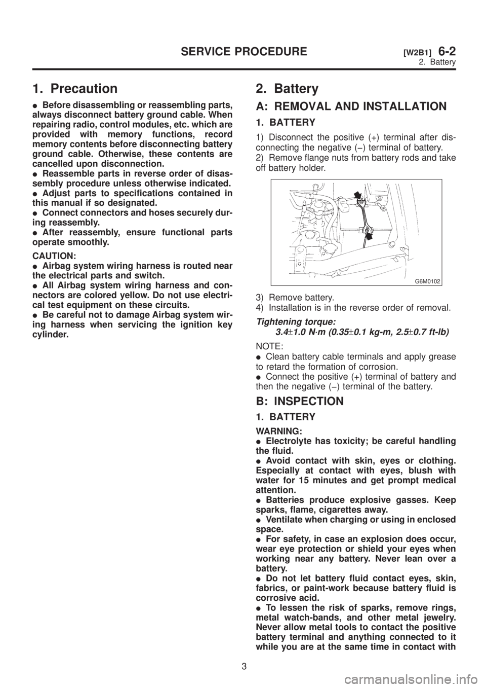
2) Remove flange nuts from battery rods and take
off battery holder.
G6M0102
3) Remove battery.
4) Installation is in the reverse order of removal.
Tightening torque:
3.4
±1.0 N´m (0.35±0.1 kg-m, 2.5±0.7 ft-lb)
NOTE:
IClean battery cable terminals and apply grease
to retard the formation of corrosion.
IConnect the positive (+) terminal of battery and
then the negative (þ) terminal of the battery.
B: INSPECTION
1. BATTERY
WARNING:
IElectrolyte has toxicity; be careful handling
the fluid.
IAvoid contact with skin, eyes or clothing.
Especially at contact with eyes, blush with
water for 15 minutes and get prompt medical
attention.
IBatteries produce explosive gasses. Keep
sparks, flame, cigarettes away.
IVentilate when charging or using in enclosed
space.
IFor safety, in case an explosion does occur,
wear eye protection or shield your eyes when
working near any battery. Never lean over a
battery.
IDo not let battery fluid contact eyes, skin,
fabrics, or paint-work because battery fluid is
corrosive acid.
ITo lessen the risk of sparks, remove rings,
metal watch-bands, and other metal jewelry.
Never allow metal tools to contact the positive
battery terminal and anything connected to it
while you are at the same time in contact with
3
[W2B1]6-2SERVICE PROCEDURE
2. Battery
Page 1228 of 1456
1. Precaution
IBefore disassembling or reassembling parts,
always disconnect battery ground cable. When
repairing radio, control modules, etc. which are
provided with memory functions, record
memory contents before disconnecting battery
ground cable. Otherwise, these contents are
cancelled upon disconnection.
IReassemble parts in reverse order of disas-
sembly procedure unless otherwise indicated.
IAdjust parts to specifications contained in
this manual if so designated.
IConnect connectors and hoses securely dur-
ing reassembly.
IAfter reassembly, ensure functional parts
operate smoothly.
CAUTION:
IAirbag system wiring harness is routed near
the electrical parts and switch.
IAll Airbag system wiring harness and con-
nectors are colored yellow. Do not use electri-
cal test equipment on these circuits.
IBe careful not to damage Airbag system wir-
ing harness when servicing the ignition key
cylinder.
2. Battery
A: REMOVAL AND INSTALLATION
1. BATTERY
1) Disconnect the positive (+) terminal after dis-
connecting the negative (þ) terminal of battery.
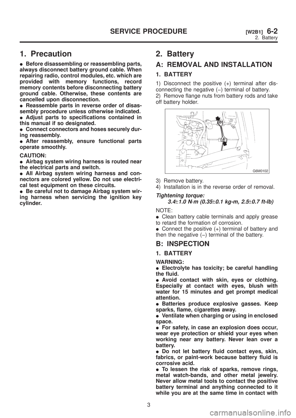
2) Remove flange nuts from battery rods and take
off battery holder.
G6M0102
3) Remove battery.
4) Installation is in the reverse order of removal.
Tightening torque:
3.4
±1.0 N´m (0.35±0.1 kg-m, 2.5±0.7 ft-lb)
NOTE:
IClean battery cable terminals and apply grease
to retard the formation of corrosion.
IConnect the positive (+) terminal of battery and
then the negative (þ) terminal of the battery.
B: INSPECTION
1. BATTERY
WARNING:
IElectrolyte has toxicity; be careful handling
the fluid.
IAvoid contact with skin, eyes or clothing.
Especially at contact with eyes, blush with
water for 15 minutes and get prompt medical
attention.
IBatteries produce explosive gasses. Keep
sparks, flame, cigarettes away.
IVentilate when charging or using in enclosed
space.
IFor safety, in case an explosion does occur,
wear eye protection or shield your eyes when
working near any battery. Never lean over a
battery.
IDo not let battery fluid contact eyes, skin,
fabrics, or paint-work because battery fluid is
corrosive acid.
ITo lessen the risk of sparks, remove rings,
metal watch-bands, and other metal jewelry.
Never allow metal tools to contact the positive
battery terminal and anything connected to it
while you are at the same time in contact with
3
[W2B1]6-2SERVICE PROCEDURE
2. Battery
Page 1229 of 1456
any other metallic portion of the vehicle
because a short circuit will be caused.
1) External parts:
Check for the existence of dirt or cracks on the
battery case, top cover, vent plugs, and terminal
posts. If necessary, clean with water and wipe with
a dry cloth. Apply a thin coat of grease on the ter-
minal posts to prevent corrosion.
2) Electrolyte level:
Check the electrolyte level in each cell. If the level
is below MIN LEVEL, bring the level to MAX
LEVEL by pouring distilled water into the battery
cell. Do not fill beyond MAX LEVEL.
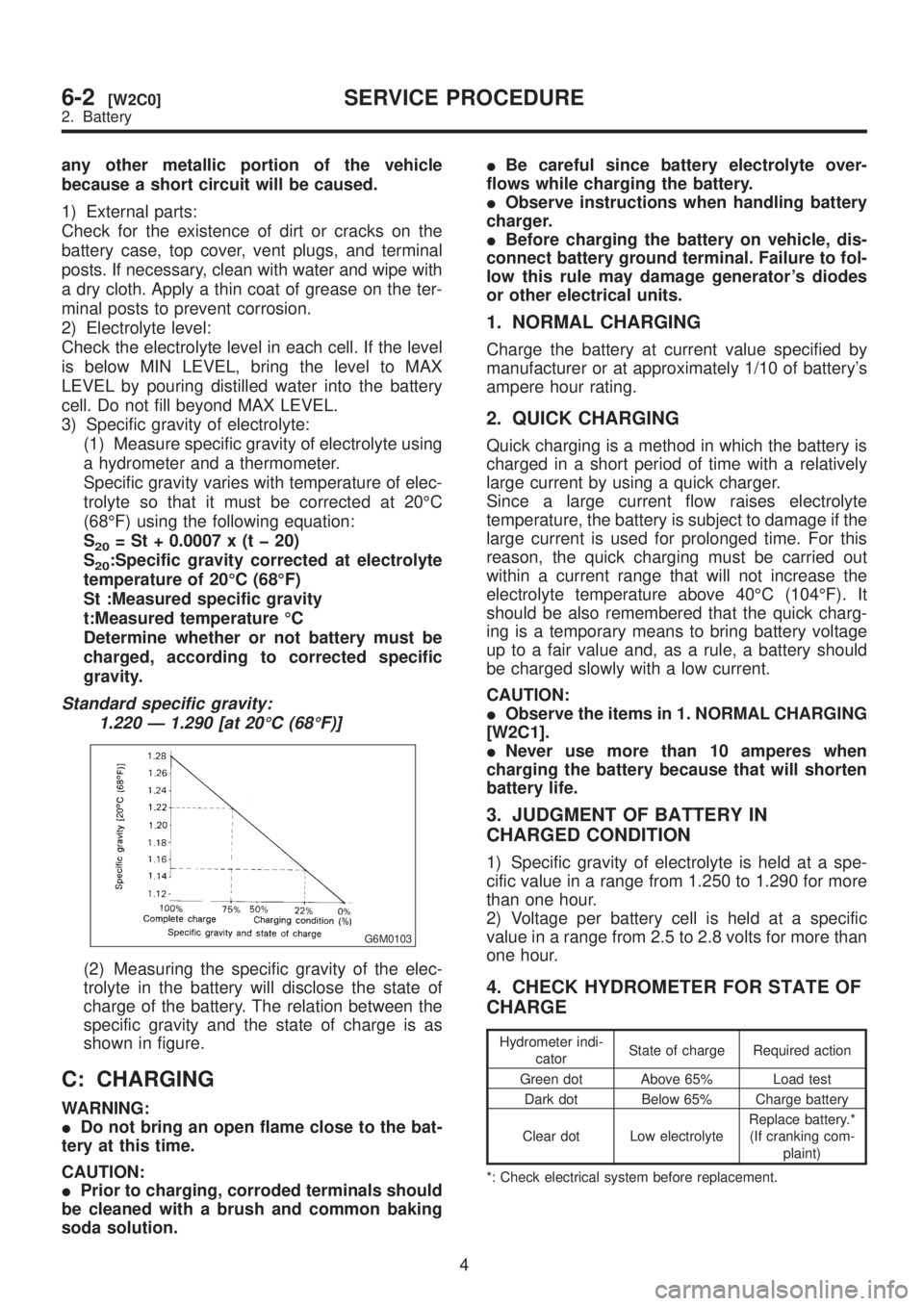
3) Specific gravity of electrolyte:
(1) Measure specific gravity of electrolyte using
a hydrometer and a thermometer.
Specific gravity varies with temperature of elec-
trolyte so that it must be corrected at 20ÉC
(68ÉF) using the following equation:
S
20= St + 0.0007 x (t þ 20)
S
20:Specific gravity corrected at electrolyte
temperature of 20ÉC (68ÉF)
St :Measured specific gravity
t:Measured temperature ÉC
Determine whether or not battery must be
charged, according to corrected specific
gravity.
Standard specific gravity:
1.220 Ð 1.290 [at 20ÉC (68ÉF)]
G6M0103
(2) Measuring the specific gravity of the elec-
trolyte in the battery will disclose the state of
charge of the battery. The relation between the
specific gravity and the state of charge is as
shown in figure.
C: CHARGING
WARNING:
IDo not bring an open flame close to the bat-
tery at this time.
CAUTION:
IPrior to charging, corroded terminals should
be cleaned with a brush and common baking
soda solution.IBe careful since battery electrolyte over-
flows while charging the battery.
IObserve instructions when handling battery
charger.
IBefore charging the battery on vehicle, dis-
connect battery ground terminal. Failure to fol-
low this rule may damage generator's diodes
or other electrical units.
1. NORMAL CHARGING
Charge the battery at current value specified by
manufacturer or at approximately 1/10 of battery's
ampere hour rating.
2. QUICK CHARGING
Quick charging is a method in which the battery is
charged in a short period of time with a relatively
large current by using a quick charger.
Since a large current flow raises electrolyte
temperature, the battery is subject to damage if the
large current is used for prolonged time. For this
reason, the quick charging must be carried out
within a current range that will not increase the
electrolyte temperature above 40ÉC (104ÉF). It
should be also remembered that the quick charg-
ing is a temporary means to bring battery voltage
up to a fair value and, as a rule, a battery should
be charged slowly with a low current.
CAUTION:
IObserve the items in 1. NORMAL CHARGING
[W2C1].
INever use more than 10 amperes when
charging the battery because that will shorten
battery life.
3. JUDGMENT OF BATTERY IN
CHARGED CONDITION
1) Specific gravity of electrolyte is held at a spe-
cific value in a range from 1.250 to 1.290 for more
than one hour.
2) Voltage per battery cell is held at a specific
value in a range from 2.5 to 2.8 volts for more than
one hour.
4. CHECK HYDROMETER FOR STATE OF
CHARGE
Hydrometer indi-
catorState of charge Required action
Green dot Above 65% Load test
Dark dot Below 65% Charge battery
Clear dot Low electrolyteReplace battery.*
(If cranking com-
plaint)
*: Check electrical system before replacement.
4
6-2[W2C0]SERVICE PROCEDURE
2. Battery
Page 1230 of 1456
3. Ignition Switch
A: REMOVAL AND INSTALLATION
1. IGNITION SWITCH
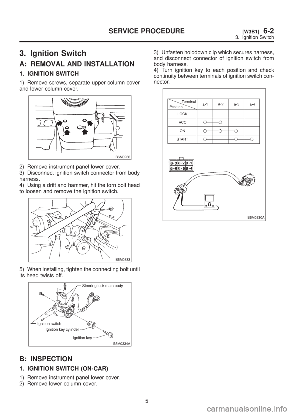
1) Remove screws, separate upper column cover
and lower column cover.
B6M0236
2) Remove instrument panel lower cover.
3) Disconnect ignition switch connector from body
harness.
4) Using a drift and hammer, hit the torn bolt head
to loosen and remove the ignition switch.
B6M0333
5) When installing, tighten the connecting bolt until
its head twists off.
B6M0334A
B: INSPECTION
1. IGNITION SWITCH (ON-CAR)
1) Remove instrument panel lower cover.
2) Remove lower column cover.3) Unfasten holddown clip which secures harness,
and disconnect connector of ignition switch from
body harness.
4) Turn ignition key to each position and check
continuity between terminals of ignition switch con-
nector.
B6M0830A
5
[W3B1]6-2SERVICE PROCEDURE
3. Ignition Switch