SUBARU LEGACY 1999 Service Repair Manual
Manufacturer: SUBARU, Model Year: 1999, Model line: LEGACY, Model: SUBARU LEGACY 1999Pages: 1456, PDF Size: 59.93 MB
Page 1261 of 1456
![SUBARU LEGACY 1999 Service Repair Manual B6M0711
2. SUB SWITCH
Set power window sub switch to each position and
check continuity between terminals.
B6M0130A
32
6-2[W17B2]SERVICE PROCEDURE
17. Power Window SUBARU LEGACY 1999 Service Repair Manual B6M0711
2. SUB SWITCH
Set power window sub switch to each position and
check continuity between terminals.
B6M0130A
32
6-2[W17B2]SERVICE PROCEDURE
17. Power Window](/img/17/57435/w960_57435-1260.png)
B6M0711
2. SUB SWITCH
Set power window sub switch to each position and
check continuity between terminals.
B6M0130A
32
6-2[W17B2]SERVICE PROCEDURE
17. Power Window
Page 1262 of 1456
B6M0712A
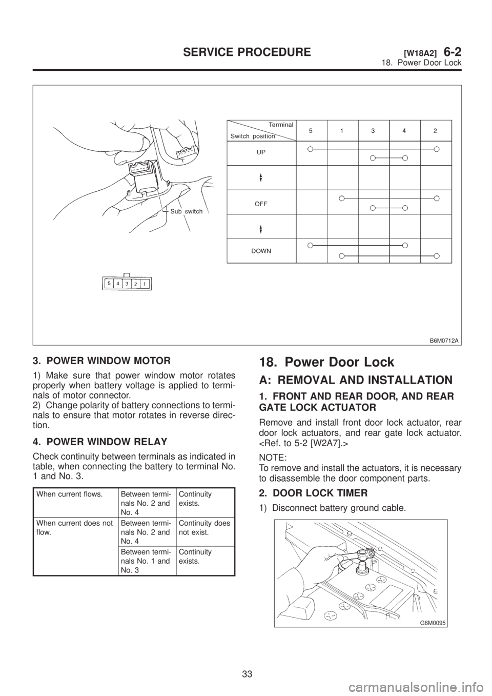
3. POWER WINDOW MOTOR
1) Make sure that power window motor rotates
properly when battery voltage is applied to termi-
nals of motor connector.
2) Change polarity of battery connections to termi-
nals to ensure that motor rotates in reverse direc-
tion.
4. POWER WINDOW RELAY
Check continuity between terminals as indicated in
table, when connecting the battery to terminal No.
1 and No. 3.
When current flows. Between termi-
nals No. 2 and
No. 4Continuity
exists.
When current does not
flow.Between termi-
nals No. 2 and
No. 4Continuity does
not exist.
Between termi-
nals No. 1 and
No. 3Continuity
exists.
18. Power Door Lock
A: REMOVAL AND INSTALLATION
1. FRONT AND REAR DOOR, AND REAR
GATE LOCK ACTUATOR
Remove and install front door lock actuator, rear
door lock actuators, and rear gate lock actuator.
NOTE:
To remove and install the actuators, it is necessary
to disassemble the door component parts.
2. DOOR LOCK TIMER
1) Disconnect battery ground cable.
G6M0095
33
[W18A2]6-2SERVICE PROCEDURE
18. Power Door Lock
Page 1263 of 1456
B6M0712A
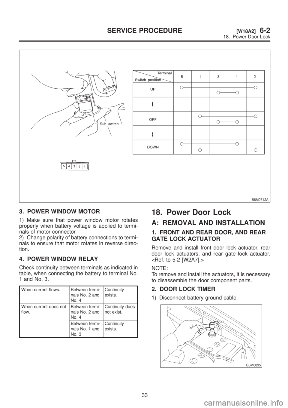
3. POWER WINDOW MOTOR
1) Make sure that power window motor rotates
properly when battery voltage is applied to termi-
nals of motor connector.
2) Change polarity of battery connections to termi-
nals to ensure that motor rotates in reverse direc-
tion.
4. POWER WINDOW RELAY
Check continuity between terminals as indicated in
table, when connecting the battery to terminal No.
1 and No. 3.
When current flows. Between termi-
nals No. 2 and
No. 4Continuity
exists.
When current does not
flow.Between termi-
nals No. 2 and
No. 4Continuity does
not exist.
Between termi-
nals No. 1 and
No. 3Continuity
exists.
18. Power Door Lock
A: REMOVAL AND INSTALLATION
1. FRONT AND REAR DOOR, AND REAR
GATE LOCK ACTUATOR
Remove and install front door lock actuator, rear
door lock actuators, and rear gate lock actuator.
NOTE:
To remove and install the actuators, it is necessary
to disassemble the door component parts.
2. DOOR LOCK TIMER
1) Disconnect battery ground cable.
G6M0095
33
[W18A2]6-2SERVICE PROCEDURE
18. Power Door Lock
Page 1264 of 1456
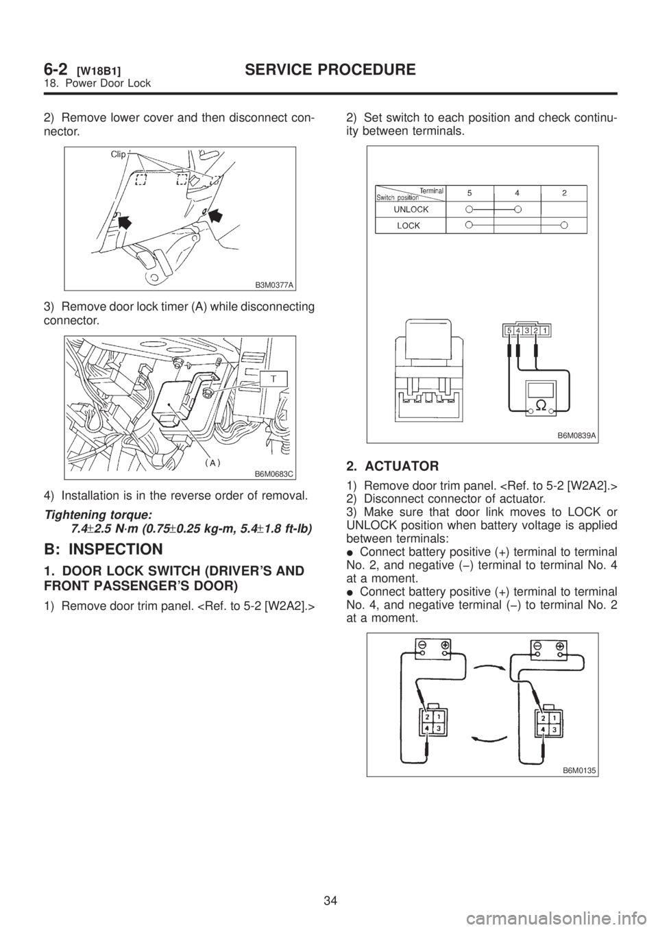
2) Remove lower cover and then disconnect con-
nector.
B3M0377A
3) Remove door lock timer (A) while disconnecting
connector.
B6M0683C
4) Installation is in the reverse order of removal.
Tightening torque:
7.4
±2.5 N´m (0.75±0.25 kg-m, 5.4±1.8 ft-lb)
B: INSPECTION
1. DOOR LOCK SWITCH (DRIVER'S AND
FRONT PASSENGER'S DOOR)
1) Remove door trim panel.
ity between terminals.
B6M0839A
2. ACTUATOR
1) Remove door trim panel.
2) Disconnect connector of actuator.
3) Make sure that door link moves to LOCK or
UNLOCK position when battery voltage is applied
between terminals:
IConnect battery positive (+) terminal to terminal
No. 2, and negative (þ) terminal to terminal No. 4
at a moment.
IConnect battery positive (+) terminal to terminal
No. 4, and negative terminal (þ) to terminal No. 2
at a moment.
B6M0135
34
6-2[W18B1]SERVICE PROCEDURE
18. Power Door Lock
Page 1265 of 1456
19. Remote Controlled
Rearview Mirror
A: REMOVAL AND INSTALLATION
1. REMOTE CONTROLLED REARVIEW
MIRROR SWITCH
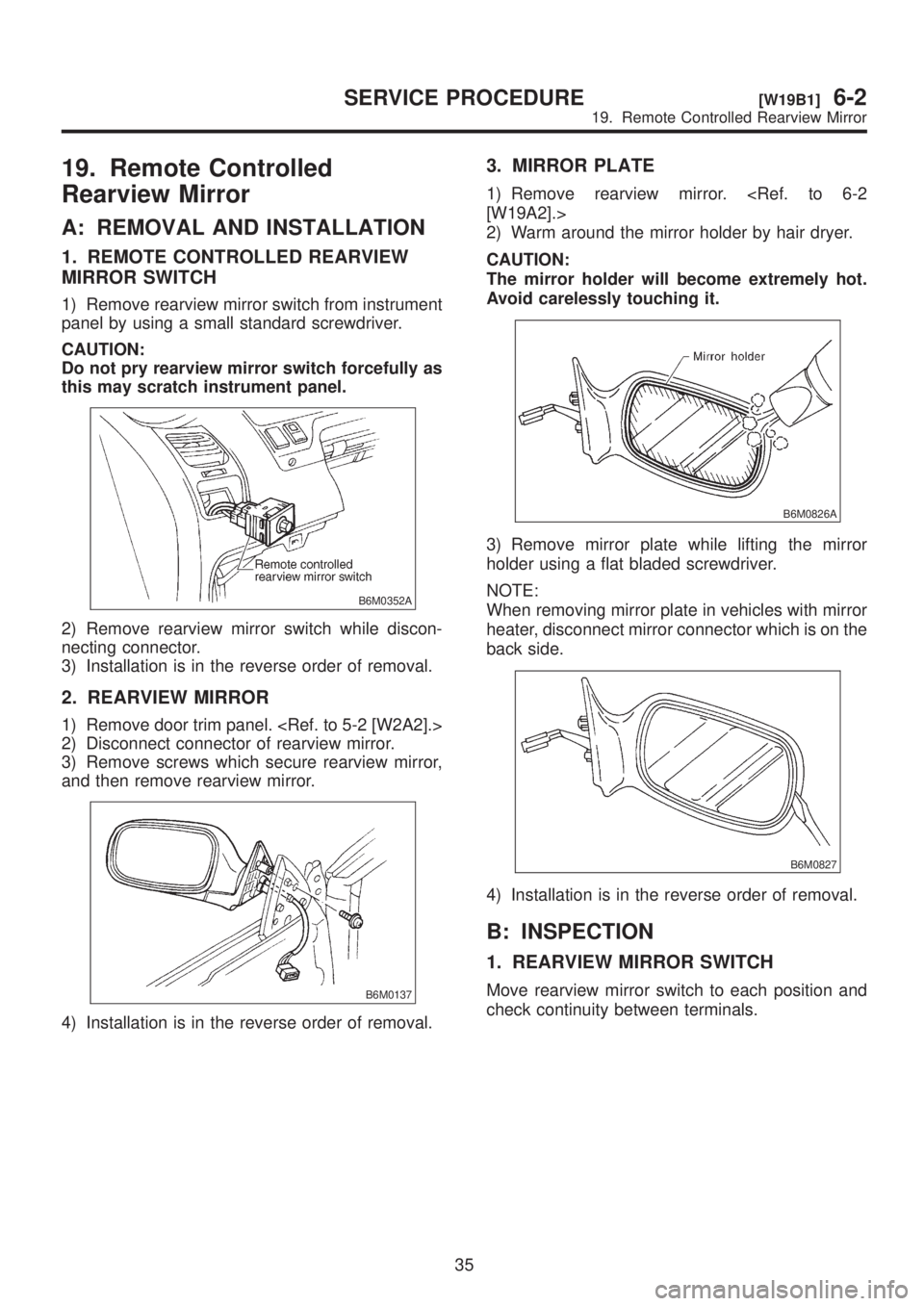
1) Remove rearview mirror switch from instrument
panel by using a small standard screwdriver.
CAUTION:
Do not pry rearview mirror switch forcefully as
this may scratch instrument panel.
B6M0352A
2) Remove rearview mirror switch while discon-
necting connector.
3) Installation is in the reverse order of removal.
2. REARVIEW MIRROR
1) Remove door trim panel.
2) Disconnect connector of rearview mirror.
3) Remove screws which secure rearview mirror,
and then remove rearview mirror.
B6M0137
4) Installation is in the reverse order of removal.
3. MIRROR PLATE
1) Remove rearview mirror.
2) Warm around the mirror holder by hair dryer.
CAUTION:
The mirror holder will become extremely hot.
Avoid carelessly touching it.
B6M0826A
3) Remove mirror plate while lifting the mirror
holder using a flat bladed screwdriver.
NOTE:
When removing mirror plate in vehicles with mirror
heater, disconnect mirror connector which is on the
back side.
B6M0827
4) Installation is in the reverse order of removal.
B: INSPECTION
1. REARVIEW MIRROR SWITCH
Move rearview mirror switch to each position and
check continuity between terminals.
35
[W19B1]6-2SERVICE PROCEDURE
19. Remote Controlled Rearview Mirror
Page 1266 of 1456
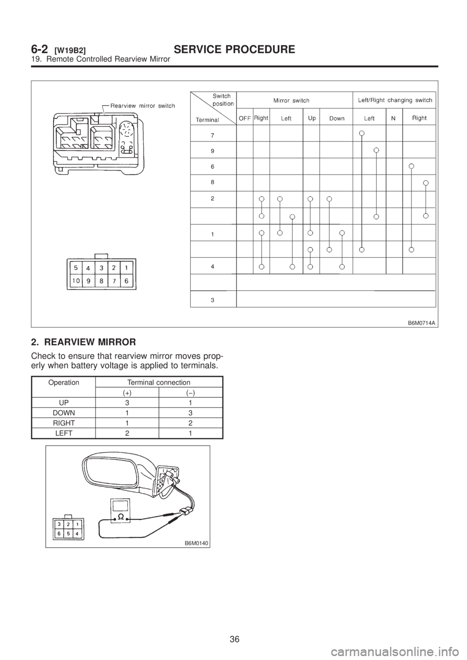
B6M0714A
2. REARVIEW MIRROR
Check to ensure that rearview mirror moves prop-
erly when battery voltage is applied to terminals.
Operation Terminal connection
(+) (þ)
UP 3 1
DOWN 1 3
RIGHT 1 2
LEFT 2 1
B6M0140
36
6-2[W19B2]SERVICE PROCEDURE
19. Remote Controlled Rearview Mirror
Page 1267 of 1456
![SUBARU LEGACY 1999 Service Repair Manual 20. Sunroof
A: REMOVAL AND INSTALLATION
1. SUNROOF AND SUNROOF MOTOR
<Ref. to 5-1 [W1600].> as for removal and instal-
lation of sunroof system.
2. SUNROOF SWITCH
NOTE:
The sunroof switch is installed SUBARU LEGACY 1999 Service Repair Manual 20. Sunroof
A: REMOVAL AND INSTALLATION
1. SUNROOF AND SUNROOF MOTOR
<Ref. to 5-1 [W1600].> as for removal and instal-
lation of sunroof system.
2. SUNROOF SWITCH
NOTE:
The sunroof switch is installed](/img/17/57435/w960_57435-1266.png)
20. Sunroof
A: REMOVAL AND INSTALLATION
1. SUNROOF AND SUNROOF MOTOR
lation of sunroof system.
2. SUNROOF SWITCH
NOTE:
The sunroof switch is installed in spot light body.
1) Pry spot light lens off using a screwdriver.
2) Remove screws which secure spot light body.
3) Remove spot light body while disconnecting
connectors.
4) Remove screw which secures sunroof switch,
and then remove sunroof switch.
B6M0141A
5) Installation is in the reverse order of removal.
B: INSPECTION
1. SUNROOF SWITCH
Set sunroof switch to each position and check con-
tinuity between terminals as indicated in table
below:
B6M0142A
B6M0861A
37
[W20B1]6-2SERVICE PROCEDURE
20. Sunroof
Page 1268 of 1456

2. SUNROOF MOTOR
1) Apply battery voltage between 1-pin connector
(Except OUTBACK) or terminal No. 1 (OUTBACK)
and body ground wire.
2) Make sure that sunroof motor moves when con-
necting terminals as described below:
Except OUTBACK
IConnect between terminals No. 3 and 4 (OPEN)
IConnect between terminals No. 6 and 4
(CLOSE)
IConnect between terminals No. 5 and 4 (TILT
UP)
IConnect between terminals No. 2 and 4 (TILT
DOWN)
OUTBACK (Rear)
IConnect between terminals No. 2 and 3 (OPEN)
IConnect between terminals No. 6 and 3
(CLOSE)
B6M0893A
OUTBACK (Front)
IConnect between terminals No. 1 and 2 (TILT
UP)
IConnect between terminals No. 2 and 1 (TILT
DOWN)
B6M0788B
3. SUNROOF RELAY
Check continuity between terminals as indicated in
table below, when battery voltage is applied
between terminals No. 1 and No. 2.
When current
flows.Between terminals
No. 3 and No. 4Continuity exists.
When current
does not flow.Between terminals
No. 3 and No. 4Continuity does not
exist.
Between terminals
No. 1 and No. 2Continuity exists.
B6M0785A
38
6-2[W20B2]SERVICE PROCEDURE
20. Sunroof
Page 1269 of 1456
21. Radio, Speaker and
Antenna
A: REMOVAL AND INSTALLATION
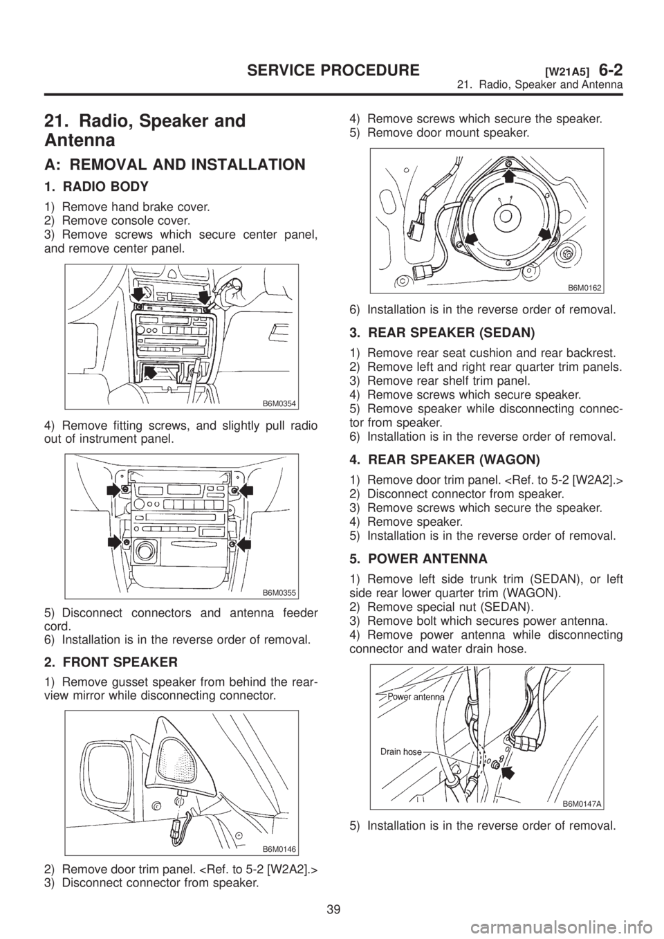
1. RADIO BODY
1) Remove hand brake cover.
2) Remove console cover.
3) Remove screws which secure center panel,
and remove center panel.
B6M0354
4) Remove fitting screws, and slightly pull radio
out of instrument panel.
B6M0355
5) Disconnect connectors and antenna feeder
cord.
6) Installation is in the reverse order of removal.
2. FRONT SPEAKER
1) Remove gusset speaker from behind the rear-
view mirror while disconnecting connector.
B6M0146
2) Remove door trim panel.
3) Disconnect connector from speaker.4) Remove screws which secure the speaker.
5) Remove door mount speaker.
B6M0162
6) Installation is in the reverse order of removal.
3. REAR SPEAKER (SEDAN)
1) Remove rear seat cushion and rear backrest.
2) Remove left and right rear quarter trim panels.
3) Remove rear shelf trim panel.
4) Remove screws which secure speaker.
5) Remove speaker while disconnecting connec-
tor from speaker.
6) Installation is in the reverse order of removal.
4. REAR SPEAKER (WAGON)
1) Remove door trim panel.
2) Disconnect connector from speaker.
3) Remove screws which secure the speaker.
4) Remove speaker.
5) Installation is in the reverse order of removal.
5. POWER ANTENNA
1) Remove left side trunk trim (SEDAN), or left
side rear lower quarter trim (WAGON).
2) Remove special nut (SEDAN).
3) Remove bolt which secures power antenna.
4) Remove power antenna while disconnecting
connector and water drain hose.
B6M0147A
5) Installation is in the reverse order of removal.
39
[W21A5]6-2SERVICE PROCEDURE
21. Radio, Speaker and Antenna
Page 1270 of 1456
B: INSPECTION
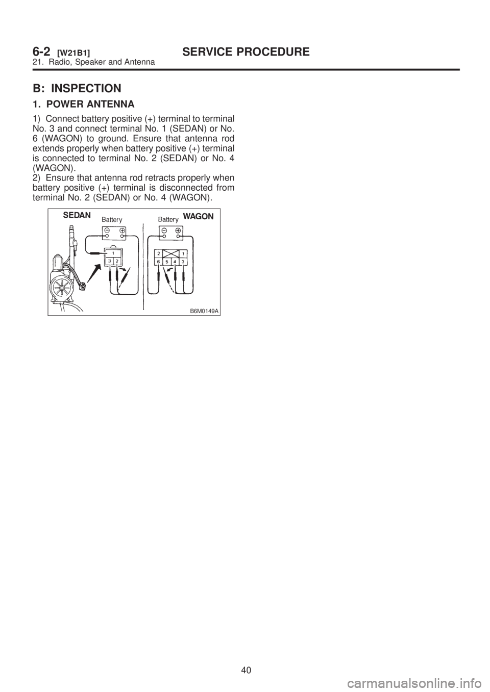
1. POWER ANTENNA
1) Connect battery positive (+) terminal to terminal
No. 3 and connect terminal No. 1 (SEDAN) or No.
6 (WAGON) to ground. Ensure that antenna rod
extends properly when battery positive (+) terminal
is connected to terminal No. 2 (SEDAN) or No. 4
(WAGON).
2) Ensure that antenna rod retracts properly when
battery positive (+) terminal is disconnected from
terminal No. 2 (SEDAN) or No. 4 (WAGON).
B6M0149A
40
6-2[W21B1]SERVICE PROCEDURE
21. Radio, Speaker and Antenna