SUBARU LEGACY 1999 Service Repair Manual
Manufacturer: SUBARU, Model Year: 1999, Model line: LEGACY, Model: SUBARU LEGACY 1999Pages: 1456, PDF Size: 59.93 MB
Page 1281 of 1456
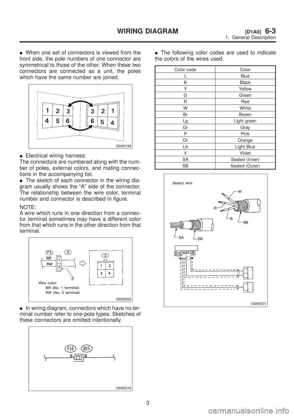
IWhen one set of connectors is viewed from the
front side, the pole numbers of one connector are
symmetrical to those of the other. When these two
connectors are connected as a unit, the poles
which have the same number are joined.
G6M0199
IElectrical wiring harness:
The connectors are numbered along with the num-
ber of poles, external colors, and mating connec-
tions in the accompanying list.
IThe sketch of each connector in the wiring dia-
gram usually shows the ªAº side of the connector.
The relationship between the wire color, terminal
number and connector is described in figure.
NOTE:
A wire which runs in one direction from a connec-
tor terminal sometimes may have a different color
from that which runs in the other direction from that
terminal.
G6M0200
IIn wiring diagram, connectors which have no ter-
minal number refer to one-pole types. Sketches of
these connectors are omitted intentionally.
G6M0216
IThe following color codes are used to indicate
the colors of the wires used.
Color code Color
L Blue
B Black
Y Yellow
G Green
R Red
W White
Br Brown
Lg Light green
Gr Gray
P Pink
Or Orange
Lb Light Blue
V Violet
SA Sealed (Inner)
SB Sealed (Outer)
G6M0201
3
[D1A0]6-3WIRING DIAGRAM
1. General Description
Page 1282 of 1456
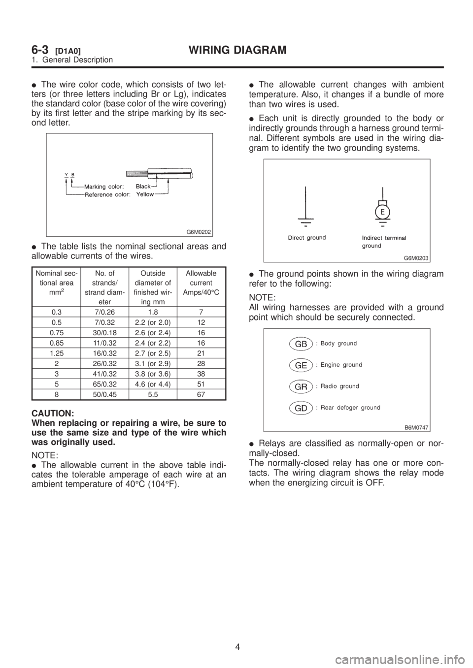
IThe wire color code, which consists of two let-
ters (or three letters including Br or Lg), indicates
the standard color (base color of the wire covering)
by its first letter and the stripe marking by its sec-
ond letter.
G6M0202
IThe table lists the nominal sectional areas and
allowable currents of the wires.
Nominal sec-
tional area
mm
2
No. of
strands/
strand diam-
eterOutside
diameter of
finished wir-
ing mmAllowable
current
Amps/40ÉC
0.3 7/0.26 1.8 7
0.5 7/0.32 2.2 (or 2.0) 12
0.75 30/0.18 2.6 (or 2.4) 16
0.85 11/0.32 2.4 (or 2.2) 16
1.25 16/0.32 2.7 (or 2.5) 21
2 26/0.32 3.1 (or 2.9) 28
3 41/0.32 3.8 (or 3.6) 38
5 65/0.32 4.6 (or 4.4) 51
8 50/0.45 5.5 67
CAUTION:
When replacing or repairing a wire, be sure to
use the same size and type of the wire which
was originally used.
NOTE:
IThe allowable current in the above table indi-
cates the tolerable amperage of each wire at an
ambient temperature of 40ÉC (104ÉF).IThe allowable current changes with ambient
temperature. Also, it changes if a bundle of more
than two wires is used.
IEach unit is directly grounded to the body or
indirectly grounds through a harness ground termi-
nal. Different symbols are used in the wiring dia-
gram to identify the two grounding systems.
G6M0203
IThe ground points shown in the wiring diagram
refer to the following:
NOTE:
All wiring harnesses are provided with a ground
point which should be securely connected.
B6M0747
IRelays are classified as normally-open or nor-
mally-closed.
The normally-closed relay has one or more con-
tacts. The wiring diagram shows the relay mode
when the energizing circuit is OFF.
4
6-3[D1A0]WIRING DIAGRAM
1. General Description
Page 1283 of 1456
![SUBARU LEGACY 1999 Service Repair Manual B6M0748
5
[D1A0]6-3WIRING DIAGRAM
1. General Description SUBARU LEGACY 1999 Service Repair Manual B6M0748
5
[D1A0]6-3WIRING DIAGRAM
1. General Description](/img/17/57435/w960_57435-1282.png)
B6M0748
5
[D1A0]6-3WIRING DIAGRAM
1. General Description
Page 1284 of 1456
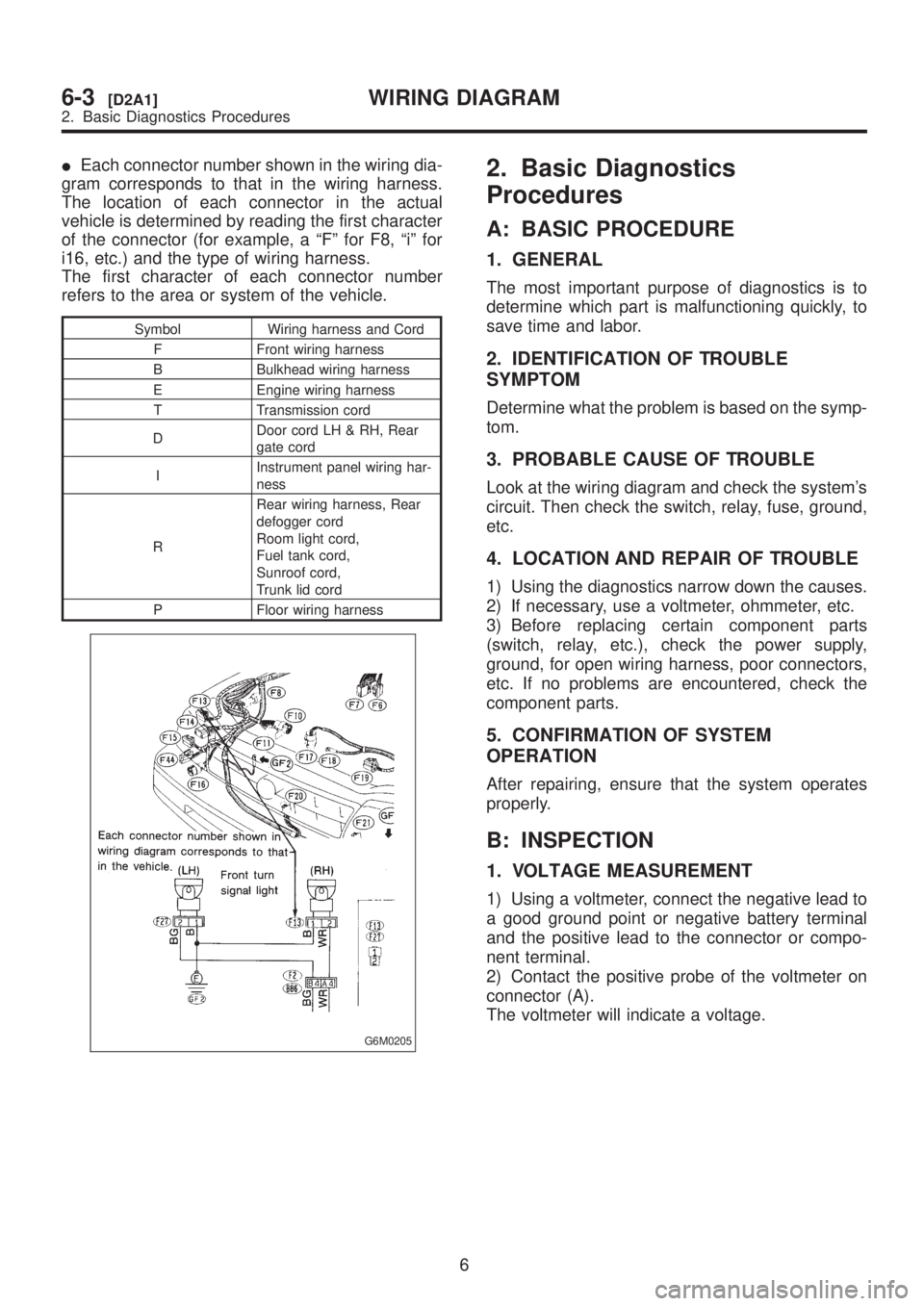
IEach connector number shown in the wiring dia-
gram corresponds to that in the wiring harness.
The location of each connector in the actual
vehicle is determined by reading the first character
of the connector (for example, a ªFº for F8, ªiº for
i16, etc.) and the type of wiring harness.
The first character of each connector number
refers to the area or system of the vehicle.
Symbol Wiring harness and Cord
F Front wiring harness
B Bulkhead wiring harness
E Engine wiring harness
T Transmission cord
DDoor cord LH & RH, Rear
gate cord
IInstrument panel wiring har-
ness
RRear wiring harness, Rear
defogger cord
Room light cord,
Fuel tank cord,
Sunroof cord,
Trunk lid cord
P Floor wiring harness
G6M0205
2. Basic Diagnostics
Procedures
A: BASIC PROCEDURE
1. GENERAL
The most important purpose of diagnostics is to
determine which part is malfunctioning quickly, to
save time and labor.
2. IDENTIFICATION OF TROUBLE
SYMPTOM
Determine what the problem is based on the symp-
tom.
3. PROBABLE CAUSE OF TROUBLE
Look at the wiring diagram and check the system's
circuit. Then check the switch, relay, fuse, ground,
etc.
4. LOCATION AND REPAIR OF TROUBLE
1) Using the diagnostics narrow down the causes.
2) If necessary, use a voltmeter, ohmmeter, etc.
3) Before replacing certain component parts
(switch, relay, etc.), check the power supply,
ground, for open wiring harness, poor connectors,
etc. If no problems are encountered, check the
component parts.
5. CONFIRMATION OF SYSTEM
OPERATION
After repairing, ensure that the system operates
properly.
B: INSPECTION
1. VOLTAGE MEASUREMENT
1) Using a voltmeter, connect the negative lead to
a good ground point or negative battery terminal
and the positive lead to the connector or compo-
nent terminal.
2) Contact the positive probe of the voltmeter on
connector (A).
The voltmeter will indicate a voltage.
6
6-3[D2A1]WIRING DIAGRAM
2. Basic Diagnostics Procedures
Page 1285 of 1456
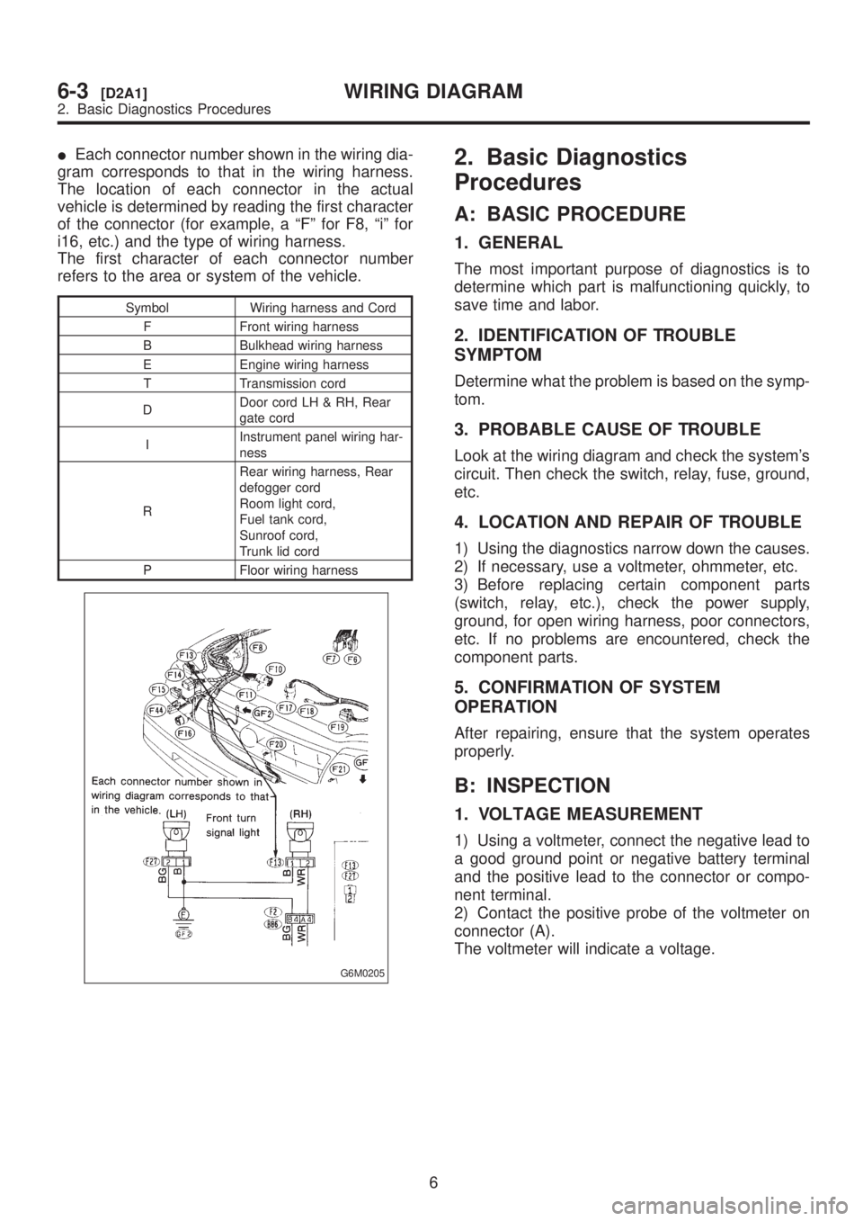
IEach connector number shown in the wiring dia-
gram corresponds to that in the wiring harness.
The location of each connector in the actual
vehicle is determined by reading the first character
of the connector (for example, a ªFº for F8, ªiº for
i16, etc.) and the type of wiring harness.
The first character of each connector number
refers to the area or system of the vehicle.
Symbol Wiring harness and Cord
F Front wiring harness
B Bulkhead wiring harness
E Engine wiring harness
T Transmission cord
DDoor cord LH & RH, Rear
gate cord
IInstrument panel wiring har-
ness
RRear wiring harness, Rear
defogger cord
Room light cord,
Fuel tank cord,
Sunroof cord,
Trunk lid cord
P Floor wiring harness
G6M0205
2. Basic Diagnostics
Procedures
A: BASIC PROCEDURE
1. GENERAL
The most important purpose of diagnostics is to
determine which part is malfunctioning quickly, to
save time and labor.
2. IDENTIFICATION OF TROUBLE
SYMPTOM
Determine what the problem is based on the symp-
tom.
3. PROBABLE CAUSE OF TROUBLE
Look at the wiring diagram and check the system's
circuit. Then check the switch, relay, fuse, ground,
etc.
4. LOCATION AND REPAIR OF TROUBLE
1) Using the diagnostics narrow down the causes.
2) If necessary, use a voltmeter, ohmmeter, etc.
3) Before replacing certain component parts
(switch, relay, etc.), check the power supply,
ground, for open wiring harness, poor connectors,
etc. If no problems are encountered, check the
component parts.
5. CONFIRMATION OF SYSTEM
OPERATION
After repairing, ensure that the system operates
properly.
B: INSPECTION
1. VOLTAGE MEASUREMENT
1) Using a voltmeter, connect the negative lead to
a good ground point or negative battery terminal
and the positive lead to the connector or compo-
nent terminal.
2) Contact the positive probe of the voltmeter on
connector (A).
The voltmeter will indicate a voltage.
6
6-3[D2A1]WIRING DIAGRAM
2. Basic Diagnostics Procedures
Page 1286 of 1456
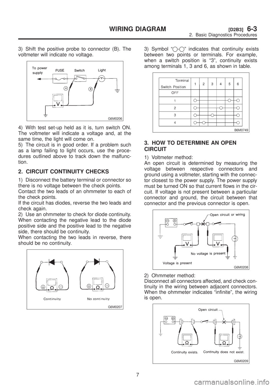
3) Shift the positive probe to connector (B). The
voltmeter will indicate no voltage.
G6M0206
4) With test set-up held as it is, turn switch ON.
The voltmeter will indicate a voltage and, at the
same time, the light will come on.
5) The circuit is in good order. If a problem such
as a lamp failing to light occurs, use the proce-
dures outlined above to track down the malfunc-
tion.
2. CIRCUIT CONTINUITY CHECKS
1) Disconnect the battery terminal or connector so
there is no voltage between the check points.
Contact the two leads of an ohmmeter to each of
the check points.
If the circuit has diodes, reverse the two leads and
check again.
2) Use an ohmmeter to check for diode continuity.
When contacting the negative lead to the diode
positive side and the positive lead to the negative
side, there should be continuity.
When contacting the two leads in reverse, there
should be no continuity.
G6M0207
3) Symbol ªq-qº indicates that continuity exists
between two points or terminals. For example,
when a switch position is ª3º, continuity exists
among terminals 1, 3 and 6, as shown in table.
B6M0749
3. HOW TO DETERMINE AN OPEN
CIRCUIT
1) Voltmeter method:
An open circuit is determined by measuring the
voltage between respective connectors and
ground using a voltmeter, starting with the connec-
tor closest to the power supply. The power supply
must be turned ON so that current flows in the cir-
cuit. If voltage is not present between a particular
connector and ground, the circuit between that
connector and the previous connector is open.
G6M0208
2) Ohmmeter method:
Disconnect all connectors affected, and check con-
tinuity in the wiring between adjacent connectors.
When the ohmmeter indicates ªinfiniteº, the wiring
is open.
G6M0209
7
[D2B3]6-3WIRING DIAGRAM
2. Basic Diagnostics Procedures
Page 1287 of 1456
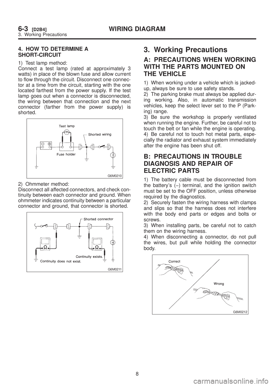
4. HOW TO DETERMINE A
SHORT-CIRCUIT
1) Test lamp method:
Connect a test lamp (rated at approximately 3
watts) in place of the blown fuse and allow current
to flow through the circuit. Disconnect one connec-
tor at a time from the circuit, starting with the one
located farthest from the power supply. If the test
lamp goes out when a connector is disconnected,
the wiring between that connection and the next
connector (farther from the power supply) is
shorted.
G6M0210
2) Ohmmeter method:
Disconnect all affected connectors, and check con-
tinuity between each connector and ground. When
ohmmeter indicates continuity between a particular
connector and ground, that connector is shorted.
G6M0211
3. Working Precautions
A: PRECAUTIONS WHEN WORKING
WITH THE PARTS MOUNTED ON
THE VEHICLE
1) When working under a vehicle which is jacked-
up, always be sure to use safety stands.
2) The parking brake must always be applied dur-
ing working. Also, in automatic transmission
vehicles, keep the select lever set to the P (Park-
ing) range.
3) Be sure the workshop is properly ventilated
when running the engine. Further, be careful not to
touch the belt or fan while the engine is operating.
4) Be careful not to touch hot metal parts, espe-
cially the radiator and exhaust system immediately
after the engine has been shut off.
B: PRECAUTIONS IN TROUBLE
DIAGNOSIS AND REPAIR OF
ELECTRIC PARTS
1) The battery cable must be disconnected from
the battery's (þ) terminal, and the ignition switch
must be set to the OFF position, unless otherwise
required by the diagnostics.
2) Securely fasten the wiring harness with clamps
and slips so that the harness does not interfere
with the body end parts or edges and bolts or
screws.
3) When installing parts, be careful not to catch
them on the wiring harness.
4) When disconnecting a connector, do not pull
the wires, but pull while holding the connector
body.
G6M0212
8
6-3[D2B4]WIRING DIAGRAM
3. Working Precautions
Page 1288 of 1456
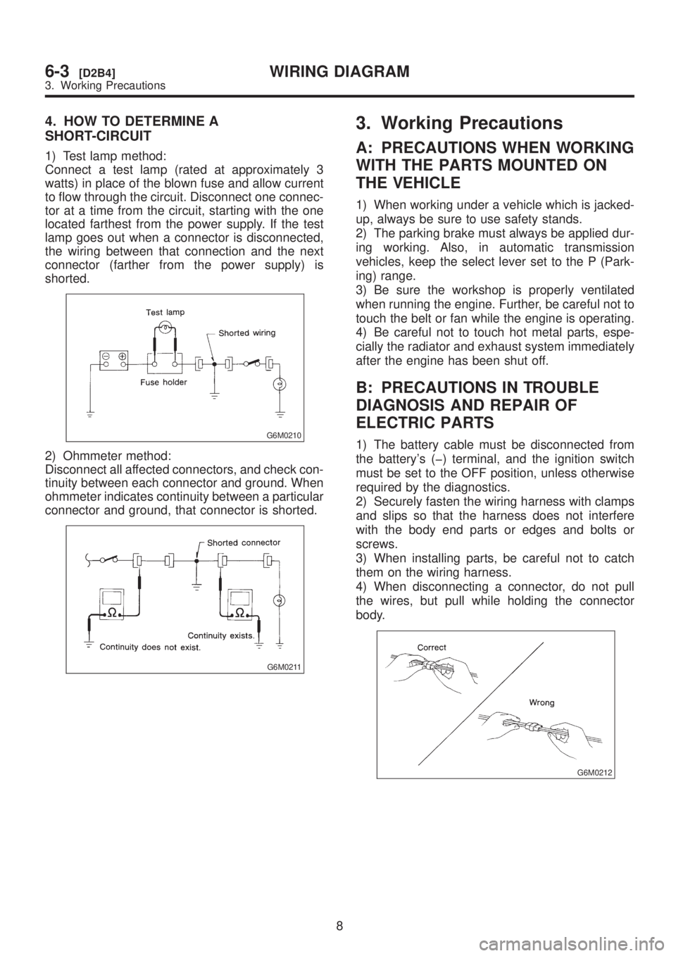
4. HOW TO DETERMINE A
SHORT-CIRCUIT
1) Test lamp method:
Connect a test lamp (rated at approximately 3
watts) in place of the blown fuse and allow current
to flow through the circuit. Disconnect one connec-
tor at a time from the circuit, starting with the one
located farthest from the power supply. If the test
lamp goes out when a connector is disconnected,
the wiring between that connection and the next
connector (farther from the power supply) is
shorted.
G6M0210
2) Ohmmeter method:
Disconnect all affected connectors, and check con-
tinuity between each connector and ground. When
ohmmeter indicates continuity between a particular
connector and ground, that connector is shorted.
G6M0211
3. Working Precautions
A: PRECAUTIONS WHEN WORKING
WITH THE PARTS MOUNTED ON
THE VEHICLE
1) When working under a vehicle which is jacked-
up, always be sure to use safety stands.
2) The parking brake must always be applied dur-
ing working. Also, in automatic transmission
vehicles, keep the select lever set to the P (Park-
ing) range.
3) Be sure the workshop is properly ventilated
when running the engine. Further, be careful not to
touch the belt or fan while the engine is operating.
4) Be careful not to touch hot metal parts, espe-
cially the radiator and exhaust system immediately
after the engine has been shut off.
B: PRECAUTIONS IN TROUBLE
DIAGNOSIS AND REPAIR OF
ELECTRIC PARTS
1) The battery cable must be disconnected from
the battery's (þ) terminal, and the ignition switch
must be set to the OFF position, unless otherwise
required by the diagnostics.
2) Securely fasten the wiring harness with clamps
and slips so that the harness does not interfere
with the body end parts or edges and bolts or
screws.
3) When installing parts, be careful not to catch
them on the wiring harness.
4) When disconnecting a connector, do not pull
the wires, but pull while holding the connector
body.
G6M0212
8
6-3[D2B4]WIRING DIAGRAM
3. Working Precautions
Page 1289 of 1456
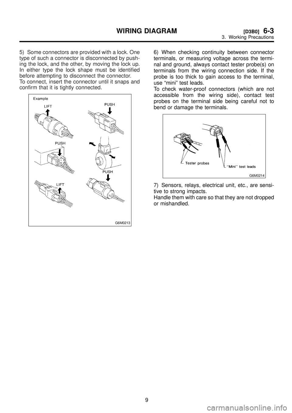
5) Some connectors are provided with a lock. One
type of such a connector is disconnected by push-
ing the lock, and the other, by moving the lock up.
In either type the lock shape must be identified
before attempting to disconnect the connector.
To connect, insert the connector until it snaps and
confirm that it is tightly connected.
G6M0213
6) When checking continuity between connector
terminals, or measuring voltage across the termi-
nal and ground, always contact tester probe(s) on
terminals from the wiring connection side. If the
probe is too thick to gain access to the terminal,
use ªminiº test leads.
To check water-proof connectors (which are not
accessible from the wiring side), contact test
probes on the terminal side being careful not to
bend or damage the terminals.
G6M0214
7) Sensors, relays, electrical unit, etc., are sensi-
tive to strong impacts.
Handle them with care so that they are not dropped
or mishandled.
9
[D3B0]6-3WIRING DIAGRAM
3. Working Precautions
Page 1290 of 1456
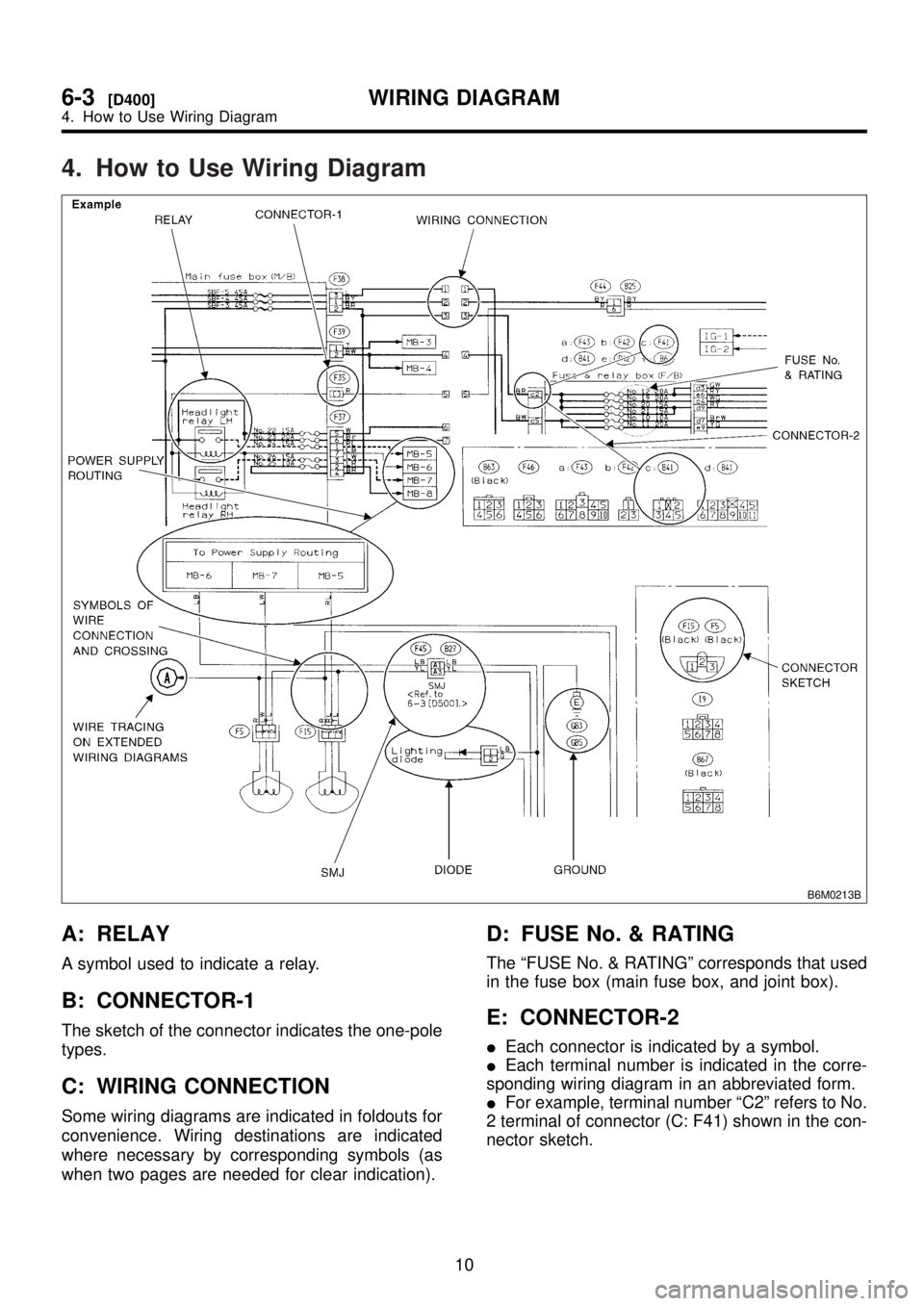
4. How to Use Wiring Diagram
B6M0213B
A: RELAY
A symbol used to indicate a relay.
B: CONNECTOR-1
The sketch of the connector indicates the one-pole
types.
C: WIRING CONNECTION
Some wiring diagrams are indicated in foldouts for
convenience. Wiring destinations are indicated
where necessary by corresponding symbols (as
when two pages are needed for clear indication).
D: FUSE No. & RATING
The ªFUSE No. & RATINGº corresponds that used
in the fuse box (main fuse box, and joint box).
E: CONNECTOR-2
IEach connector is indicated by a symbol.
IEach terminal number is indicated in the corre-
sponding wiring diagram in an abbreviated form.
IFor example, terminal number ªC2º refers to No.
2 terminal of connector (C: F41) shown in the con-
nector sketch.
10
6-3[D400]WIRING DIAGRAM
4. How to Use Wiring Diagram