SUBARU LEGACY 1999 Service Repair Manual
Manufacturer: SUBARU, Model Year: 1999, Model line: LEGACY, Model: SUBARU LEGACY 1999Pages: 1456, PDF Size: 59.93 MB
Page 1271 of 1456
22. Cruise Control
A: ADJUSTMENT
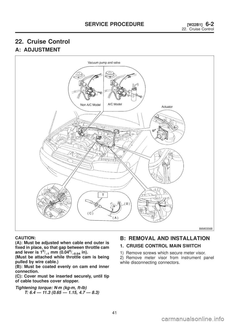
B6M0356B
CAUTION:
(A): Must be adjusted when cable end outer is
fixed in place, so that gap between throttle cam
and lever is 1
0/þ1mm (0.040/þ0.04in).
(Must be attached while throttle cam is being
pulled by wire cable.)
(B): Must be coated evenly on cam end inner
connection.
(C): Cover must be inserted securely, until tip
of cable touches cover stopper.
Tightening torque: N´m (kg-m, ft-lb)
T: 6.4 Ð 11.3 (0.65 Ð 1.15, 4.7 Ð 8.3)
B: REMOVAL AND INSTALLATION
1. CRUISE CONTROL MAIN SWITCH
1) Remove screws which secure meter visor.
2) Remove meter visor from instrument panel
while disconnecting connectors.
41
[W22B1]6-2SERVICE PROCEDURE
22. Cruise Control
Page 1272 of 1456
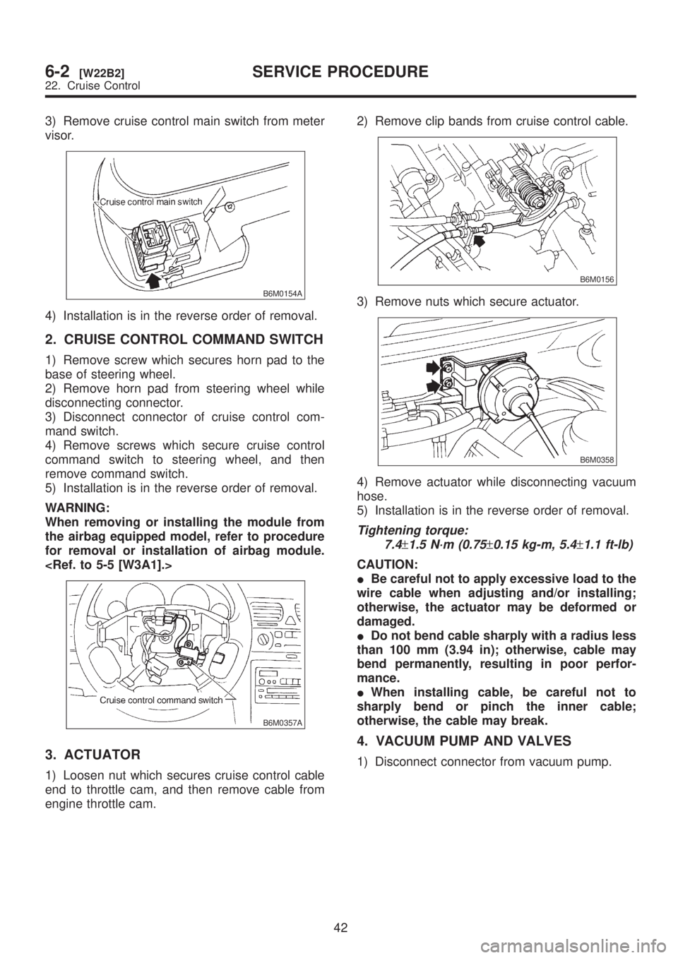
3) Remove cruise control main switch from meter
visor.
B6M0154A
4) Installation is in the reverse order of removal.
2. CRUISE CONTROL COMMAND SWITCH
1) Remove screw which secures horn pad to the
base of steering wheel.
2) Remove horn pad from steering wheel while
disconnecting connector.
3) Disconnect connector of cruise control com-
mand switch.
4) Remove screws which secure cruise control
command switch to steering wheel, and then
remove command switch.
5) Installation is in the reverse order of removal.
WARNING:
When removing or installing the module from
the airbag equipped model, refer to procedure
for removal or installation of airbag module.
B6M0357A
3. ACTUATOR
1) Loosen nut which secures cruise control cable
end to throttle cam, and then remove cable from
engine throttle cam.2) Remove clip bands from cruise control cable.
B6M0156
3) Remove nuts which secure actuator.
B6M0358
4) Remove actuator while disconnecting vacuum
hose.
5) Installation is in the reverse order of removal.
Tightening torque:
7.4
±1.5 N´m (0.75±0.15 kg-m, 5.4±1.1 ft-lb)
CAUTION:
IBe careful not to apply excessive load to the
wire cable when adjusting and/or installing;
otherwise, the actuator may be deformed or
damaged.
IDo not bend cable sharply with a radius less
than 100 mm (3.94 in); otherwise, cable may
bend permanently, resulting in poor perfor-
mance.
IWhen installing cable, be careful not to
sharply bend or pinch the inner cable;
otherwise, the cable may break.
4. VACUUM PUMP AND VALVES
1) Disconnect connector from vacuum pump.
42
6-2[W22B2]SERVICE PROCEDURE
22. Cruise Control
Page 1273 of 1456
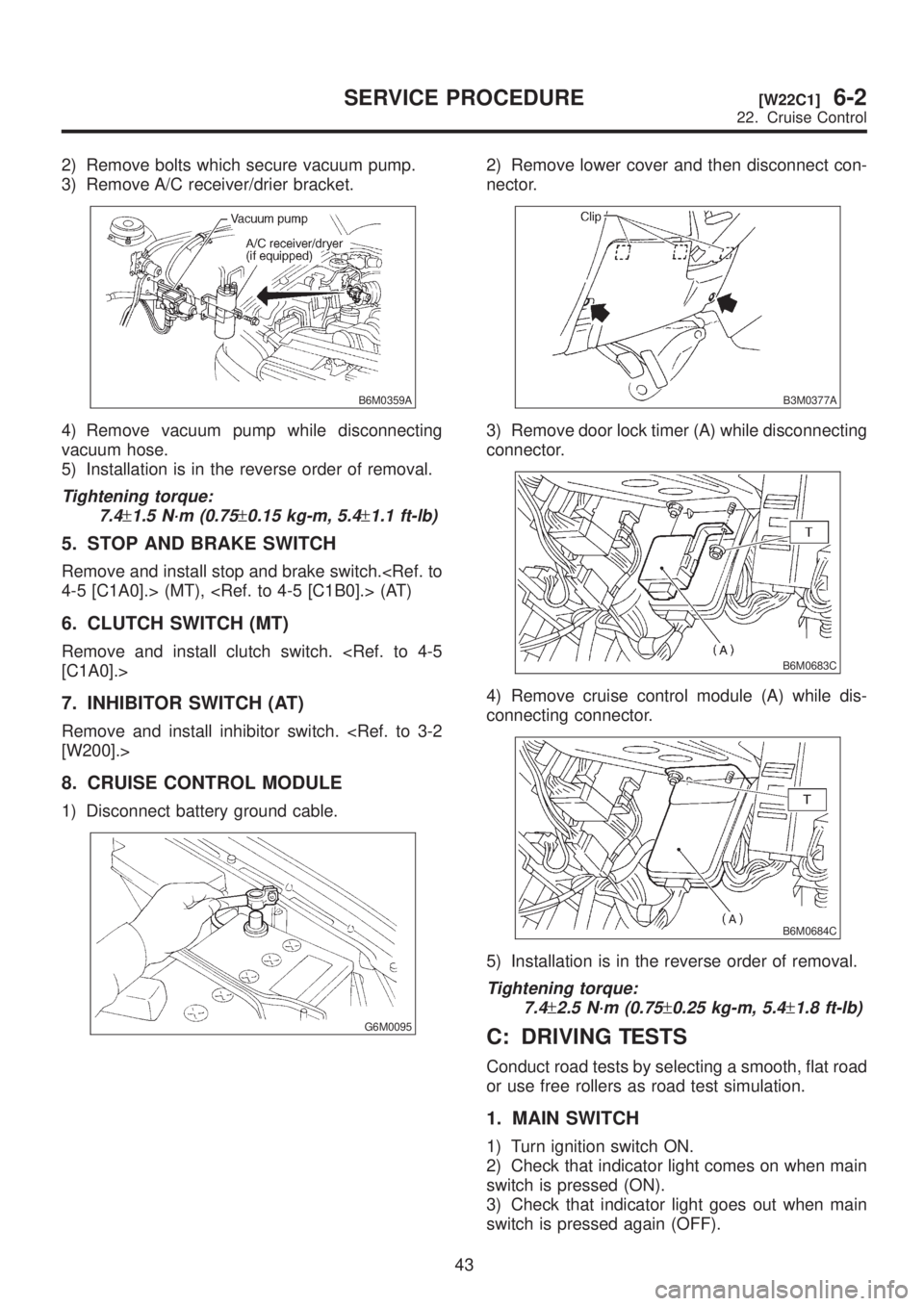
2) Remove bolts which secure vacuum pump.
3) Remove A/C receiver/drier bracket.
B6M0359A
4) Remove vacuum pump while disconnecting
vacuum hose.
5) Installation is in the reverse order of removal.
Tightening torque:
7.4
±1.5 N´m (0.75±0.15 kg-m, 5.4±1.1 ft-lb)
5. STOP AND BRAKE SWITCH
Remove and install stop and brake switch.
6. CLUTCH SWITCH (MT)
Remove and install clutch switch.
7. INHIBITOR SWITCH (AT)
Remove and install inhibitor switch.
8. CRUISE CONTROL MODULE
1) Disconnect battery ground cable.
G6M0095
2) Remove lower cover and then disconnect con-
nector.
B3M0377A
3) Remove door lock timer (A) while disconnecting
connector.
B6M0683C
4) Remove cruise control module (A) while dis-
connecting connector.
B6M0684C
5) Installation is in the reverse order of removal.
Tightening torque:
7.4
±2.5 N´m (0.75±0.25 kg-m, 5.4±1.8 ft-lb)
C: DRIVING TESTS
Conduct road tests by selecting a smooth, flat road
or use free rollers as road test simulation.
1. MAIN SWITCH
1) Turn ignition switch ON.
2) Check that indicator light comes on when main
switch is pressed (ON).
3) Check that indicator light goes out when main
switch is pressed again (OFF).
43
[W22C1]6-2SERVICE PROCEDURE
22. Cruise Control
Page 1274 of 1456
4) Turn ignition switch OFF with main switch ON
(which is indicated by illumination.).
5) Turn ignition switch ON again to ensure that
indicator light remains OFF.
2. COMMAND SWITCH
1) Check that command switch is properly set in
ªSET/COASTº, ªRESUME/ACCELº or ªCANCELº
mode.
2) Also check that command switch returns to the
original position when released.
3. CONSTANT SPEED TEST
1) Turn main switch ON.
2) Drive vehicle at speed greater than 40 km/h (25
MPH).
3) Press command switch to set in ªSET/COASTº
mode.
4) Ensure that vehicle is maintained at the speed
set when command switch was pressed.
4. ACCELERATION TEST
1) Set vehicle speed at speed greater than 40
km/h (25 MPH).
2) Ensure that vehicle continues to accelerate
while holding command switch in RESUME/
ACCEL mode, and that vehicle maintains that
optional speed when command switch is released.
5. DECELERATION TEST
1) Set vehicle speed at optional speed greater
than 40 km/h (25 MPH).
2) Ensure that vehicle continues to decelerate
while holding command switch in SET/COAST
mode, and that it maintains that optional speed
when command switch is released.
NOTE:
When vehicle speed reaches the lower speed limit
of 30 km/h (19 MPH) during deceleration, cruise
control will be released.
23. Security System
A: REMOVAL AND INSTALLATION
1. SECURITY CONTROL MODULE
1) Disconnect battery ground cable.
2) Remove radio.
3) Disconnect connector from security control
module and then remove security control module.
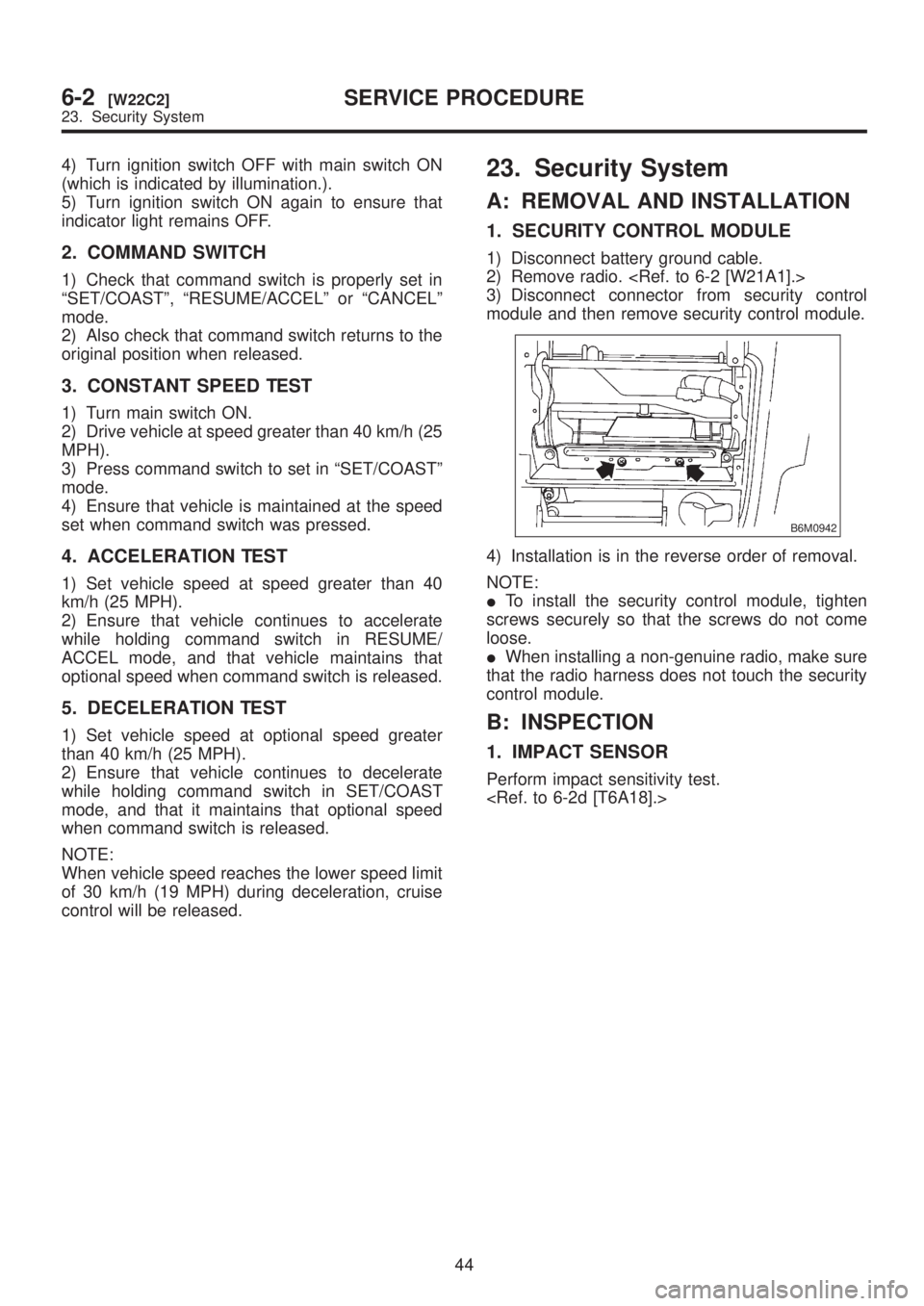
B6M0942
4) Installation is in the reverse order of removal.
NOTE:
ITo install the security control module, tighten
screws securely so that the screws do not come
loose.
IWhen installing a non-genuine radio, make sure
that the radio harness does not touch the security
control module.
B: INSPECTION
1. IMPACT SENSOR
Perform impact sensitivity test.
44
6-2[W22C2]SERVICE PROCEDURE
23. Security System
Page 1275 of 1456
4) Turn ignition switch OFF with main switch ON
(which is indicated by illumination.).
5) Turn ignition switch ON again to ensure that
indicator light remains OFF.
2. COMMAND SWITCH
1) Check that command switch is properly set in
ªSET/COASTº, ªRESUME/ACCELº or ªCANCELº
mode.
2) Also check that command switch returns to the
original position when released.
3. CONSTANT SPEED TEST
1) Turn main switch ON.
2) Drive vehicle at speed greater than 40 km/h (25
MPH).
3) Press command switch to set in ªSET/COASTº
mode.
4) Ensure that vehicle is maintained at the speed
set when command switch was pressed.
4. ACCELERATION TEST
1) Set vehicle speed at speed greater than 40
km/h (25 MPH).
2) Ensure that vehicle continues to accelerate
while holding command switch in RESUME/
ACCEL mode, and that vehicle maintains that
optional speed when command switch is released.
5. DECELERATION TEST
1) Set vehicle speed at optional speed greater
than 40 km/h (25 MPH).
2) Ensure that vehicle continues to decelerate
while holding command switch in SET/COAST
mode, and that it maintains that optional speed
when command switch is released.
NOTE:
When vehicle speed reaches the lower speed limit
of 30 km/h (19 MPH) during deceleration, cruise
control will be released.
23. Security System
A: REMOVAL AND INSTALLATION
1. SECURITY CONTROL MODULE
1) Disconnect battery ground cable.
2) Remove radio.
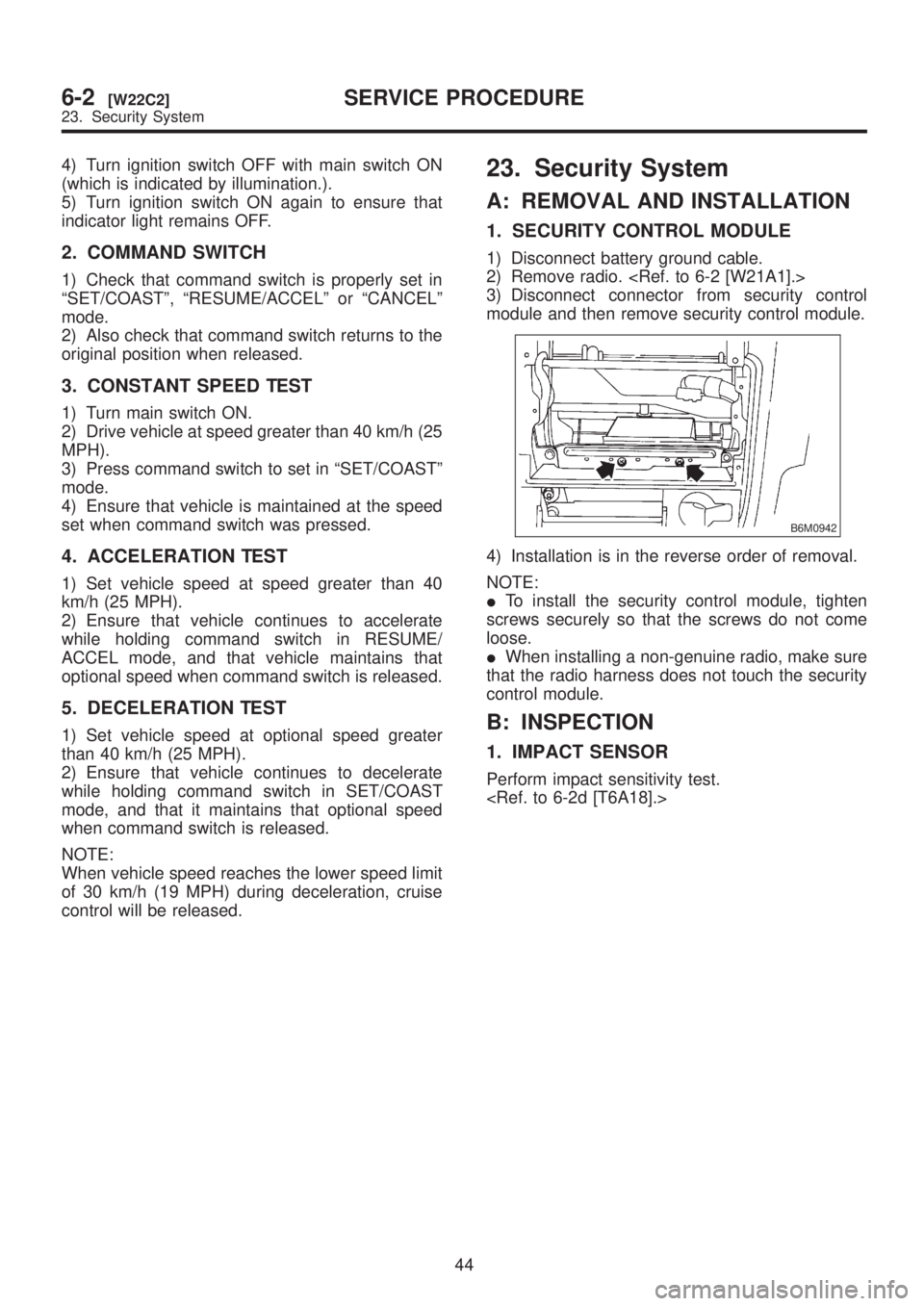
3) Disconnect connector from security control
module and then remove security control module.
B6M0942
4) Installation is in the reverse order of removal.
NOTE:
ITo install the security control module, tighten
screws securely so that the screws do not come
loose.
IWhen installing a non-genuine radio, make sure
that the radio harness does not touch the security
control module.
B: INSPECTION
1. IMPACT SENSOR
Perform impact sensitivity test.
44
6-2[W22C2]SERVICE PROCEDURE
23. Security System
Page 1276 of 1456
![SUBARU LEGACY 1999 Service Repair Manual 24. Seat Heater
A: REMOVAL AND INSTALLATION
1. SEAT HEATER
Remove and install front seat (including heater
system). <Ref. to 5-3 [W1A0].>
2. SEAT HEATER SWITCH
1) Remove screws which secure rear conso SUBARU LEGACY 1999 Service Repair Manual 24. Seat Heater
A: REMOVAL AND INSTALLATION
1. SEAT HEATER
Remove and install front seat (including heater
system). <Ref. to 5-3 [W1A0].>
2. SEAT HEATER SWITCH
1) Remove screws which secure rear conso](/img/17/57435/w960_57435-1275.png)
24. Seat Heater
A: REMOVAL AND INSTALLATION
1. SEAT HEATER
Remove and install front seat (including heater
system).
2. SEAT HEATER SWITCH
1) Remove screws which secure rear console
cover, and then remove rear console cover.
2) Remove seat heater switch from console cover.
B6M0150A
3) Installation is in the reverse order of removal.
B: INSPECTION
1. SEAT HEATER
Check continuity between terminals of seat heater
connector:
IBetween terminals No. 1 and No. 3
IBetween terminals No. 1 and No. 4
IBetween terminals No. 3 and No. 4
B6M0151A
2. SEAT HEATER SWITCH
Set switch to each position and check continuity
between terminals.
B6M0845A
45
[W24B2]6-2SERVICE PROCEDURE
24. Seat Heater
Page 1277 of 1456
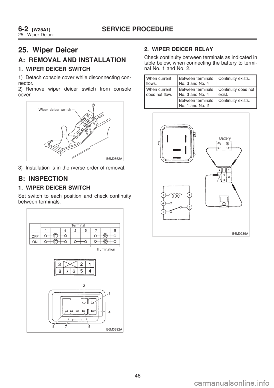
25. Wiper Deicer
A: REMOVAL AND INSTALLATION
1. WIPER DEICER SWITCH
1) Detach console cover while disconnecting con-
nector.
2) Remove wiper deicer switch from console
cover.
B6M0862A
3) Installation is in the rverse order of removal.
B: INSPECTION
1. WIPER DEICER SWITCH
Set switch to each position and check continuity
between terminals.
B6M0892A
2. WIPER DEICER RELAY
Check continuity between terminals as indicated in
table below, when connecting the battery to termi-
nal No. 1 and No. 2.
When current
flows.Between terminals
No. 3 and No. 4Continuity exists.
When current
does not flow.Between terminals
No. 3 and No. 4Continuity does not
exist.
Between terminals
No. 1 and No. 2Continuity exists.
B6M0239A
46
6-2[W25A1]SERVICE PROCEDURE
25. Wiper Deicer
Page 1278 of 1456
26. Keyless Entry
A: REMOVAL AND INSTALLATION
1. KEYLESS ENTRY CONTROL MODULE
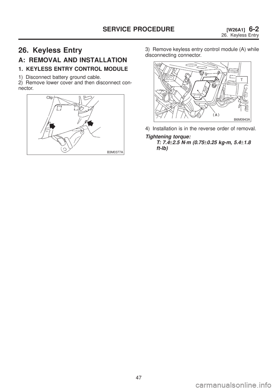
1) Disconnect battery ground cable.
2) Remove lower cover and then disconnect con-
nector.
B3M0377A
3) Remove keyless entry control module (A) while
disconnecting connector.
B6M0943A
4) Installation is in the reverse order of removal.
Tightening torque:
T: 7.4
±2.5 N´m (0.75±0.25 kg-m, 5.4±1.8
ft-lb)
47
[W26A1]6-2SERVICE PROCEDURE
26. Keyless Entry
Page 1279 of 1456

MEMO:
48
6-2SERVICE PROCEDURE
Page 1280 of 1456
1. General Description
A: WIRING DIAGRAM
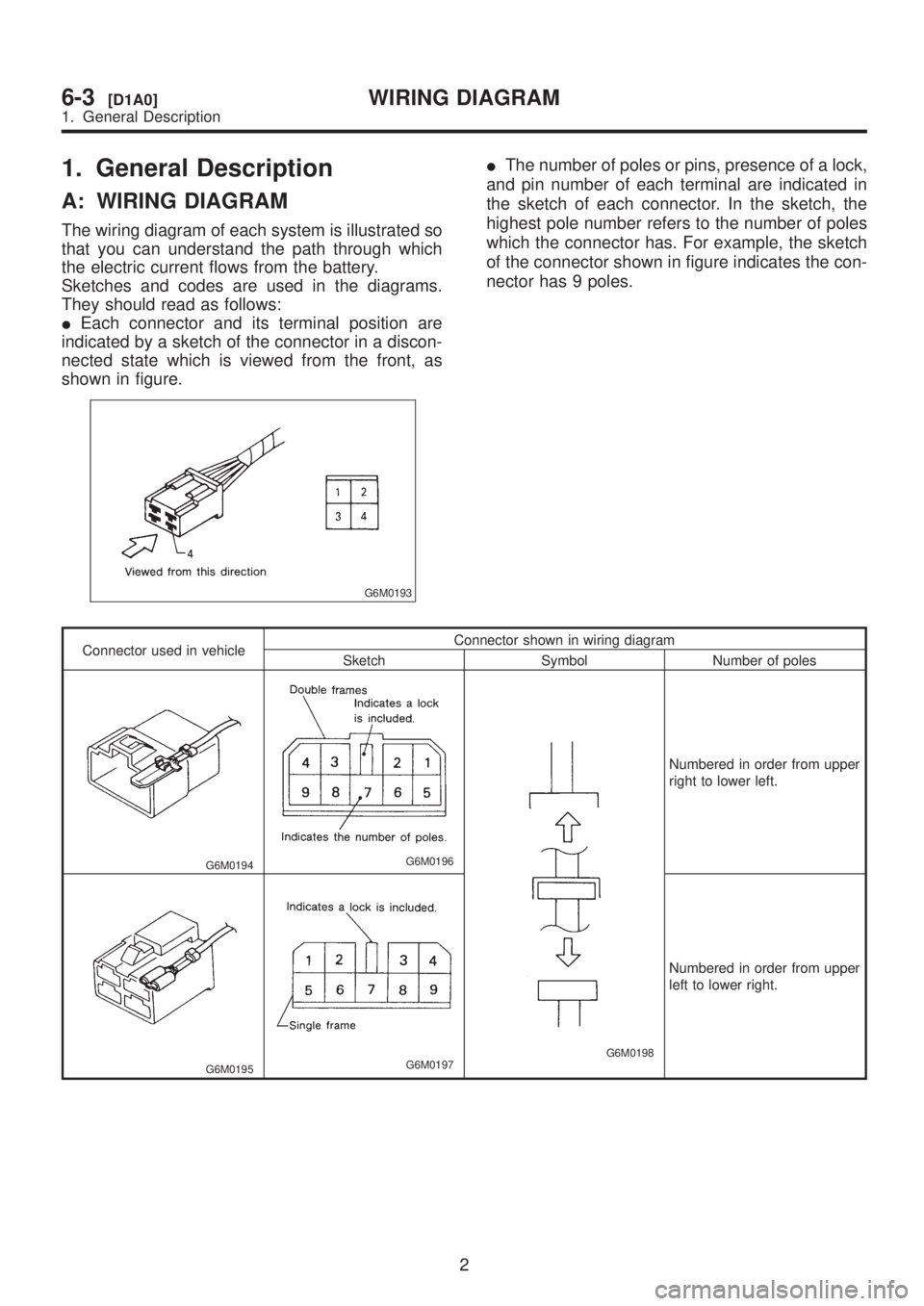
The wiring diagram of each system is illustrated so
that you can understand the path through which
the electric current flows from the battery.
Sketches and codes are used in the diagrams.
They should read as follows:
IEach connector and its terminal position are
indicated by a sketch of the connector in a discon-
nected state which is viewed from the front, as
shown in figure.
G6M0193
IThe number of poles or pins, presence of a lock,
and pin number of each terminal are indicated in
the sketch of each connector. In the sketch, the
highest pole number refers to the number of poles
which the connector has. For example, the sketch
of the connector shown in figure indicates the con-
nector has 9 poles.
Connector used in vehicleConnector shown in wiring diagram
Sketch Symbol Number of poles
G6M0194G6M0196
G6M0198
Numbered in order from upper
right to lower left.
G6M0195G6M0197
Numbered in order from upper
left to lower right.
2
6-3[D1A0]WIRING DIAGRAM
1. General Description