sensor SUBARU TRIBECA 2009 1.G Service Workshop Manual
[x] Cancel search | Manufacturer: SUBARU, Model Year: 2009, Model line: TRIBECA, Model: SUBARU TRIBECA 2009 1.GPages: 2453, PDF Size: 46.32 MB
Page 620 of 2453
SE-10
Front Seat
SEATS
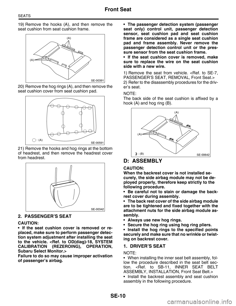
19) Remove the hooks (A), and then remove the
seat cushion from seat cushion frame.
20) Remove the hog rings (A), and then remove the
seat cushion cover from seat cushion pad.
21) Remove the hooks and hog rings at the bottom
of headrest, and then remove the headrest cover
from headrest.
2. PASSENGER’S SEAT
CAUTION:
•If the seat cushion cover is removed or re-
placed, make sure to perform passenger detec-
tion system adjustment after installing the seat
to the vehicle.
Subaru Select Monitor.>
Failure to do so may cause improper activation
of passenger’s airbag.
•The passenger detection system (passenger
seat only) control unit, passenger detection
sensor, seat cushion pad and seat cushion
frame are considered as a single seat cushion
pad and frame assembly. Never remove the
passenger detection control unit or the pres-
sure sensor from the seat cushion frame.
•If the seat cushion cover is removed, make
sure to replace the wire on the seat cushion
side with a new wire.
1) Remove the seat from vehicle.
2) Refer to the disassembly procedures for the driv-
er’s seat.
NOTE:
The back side of the seat cushion is affixed by a
hook (A) and hog ring (B).
D: ASSEMBLY
CAUTION:
When the backrest cover is not installed se-
curely, the side airbag module may not be de-
ployed properly, therefore keep strictly to the
following procedure.
•Be careful not to stain or damage the back-
rest cover during assembly.
•The back rest cover of the side airbag module
are to be tightened and fixed together with the
attachment nuts for the side airbag module as-
sembly.
•Always use new hog rings.
•Secure the hog ring using hog ring pliers.
•Install the hog rings to the specified points
securely and make sure that no wrinkle or twist-
ing on backrest cover.
1. DRIVER’S SEAT
NOTE:
•When installing the inner seat belt assembly, fol-
low the procedure described in the seat belt sec-
tion.
•Install the backrest assembly and seat cushion
assembly in the following procedure.
SE-00391
(A)
(A)
SE-00591: (A)
SE-00342
(A)
(A)
SE-00642: (B)
Page 621 of 2453
SE-11
Front Seat
SEATS
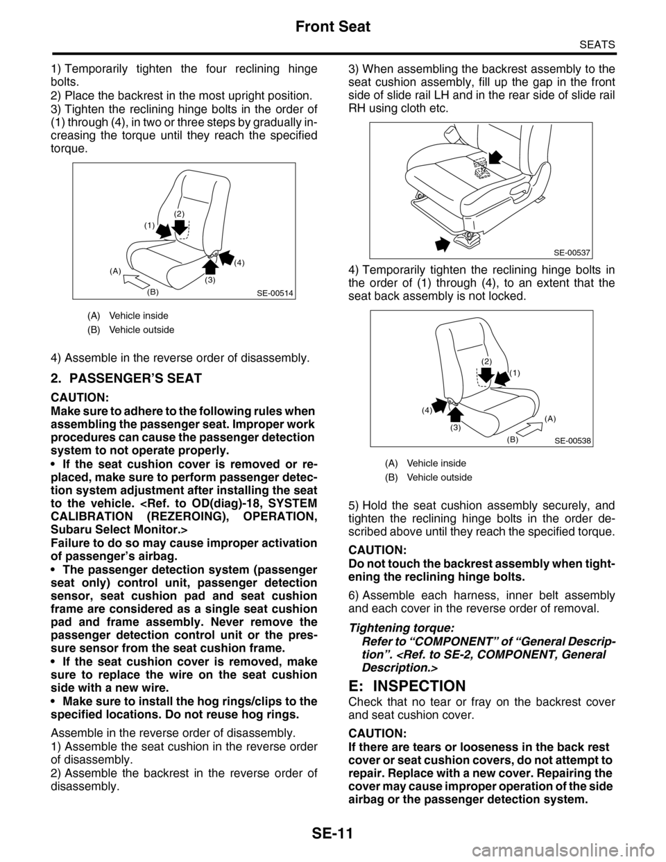
1) Temporarily tighten the four reclining hinge
bolts.
2) Place the backrest in the most upright position.
3) Tighten the reclining hinge bolts in the order of
(1) through (4), in two or three steps by gradually in-
creasing the torque until they reach the specified
torque.
4) Assemble in the reverse order of disassembly.
2. PASSENGER’S SEAT
CAUTION:
Make sure to adhere to the following rules when
assembling the passenger seat. Improper work
procedures can cause the passenger detection
system to not operate properly.
•If the seat cushion cover is removed or re-
placed, make sure to perform passenger detec-
tion system adjustment after installing the seat
to the vehicle.
Subaru Select Monitor.>
Failure to do so may cause improper activation
of passenger’s airbag.
•The passenger detection system (passenger
seat only) control unit, passenger detection
sensor, seat cushion pad and seat cushion
frame are considered as a single seat cushion
pad and frame assembly. Never remove the
passenger detection control unit or the pres-
sure sensor from the seat cushion frame.
•If the seat cushion cover is removed, make
sure to replace the wire on the seat cushion
side with a new wire.
•Make sure to install the hog rings/clips to the
specified locations. Do not reuse hog rings.
Assemble in the reverse order of disassembly.
1) Assemble the seat cushion in the reverse order
of disassembly.
2) Assemble the backrest in the reverse order of
disassembly.
3) When assembling the backrest assembly to the
seat cushion assembly, fill up the gap in the front
side of slide rail LH and in the rear side of slide rail
RH using cloth etc.
4) Temporarily tighten the reclining hinge bolts in
the order of (1) through (4), to an extent that the
seat back assembly is not locked.
5) Hold the seat cushion assembly securely, and
tighten the reclining hinge bolts in the order de-
scribed above until they reach the specified torque.
CAUTION:
Do not touch the backrest assembly when tight-
ening the reclining hinge bolts.
6) Assemble each harness, inner belt assembly
and each cover in the reverse order of removal.
Tightening torque:
Refer to “COMPONENT” of “General Descrip-
tion”.
E: INSPECTION
Check that no tear or fray on the backrest cover
and seat cushion cover.
CAUTION:
If there are tears or looseness in the back rest
cover or seat cushion covers, do not attempt to
repair. Replace with a new cover. Repairing the
cover may cause improper operation of the side
airbag or the passenger detection system.
(A) Vehicle inside
(B) Vehicle outside
(A)
(B)
(2)
(4)
(3)
(1)
SE-00514
(A) Vehicle inside
(B) Vehicle outside
SE-00537
(A)
(B)
(2)
(4)
(3)
(1)
SE-00538
Page 655 of 2453
SL-26
Security System
SECURITY AND LOCKS
4. Security System
A: WIRING DIAGRAM
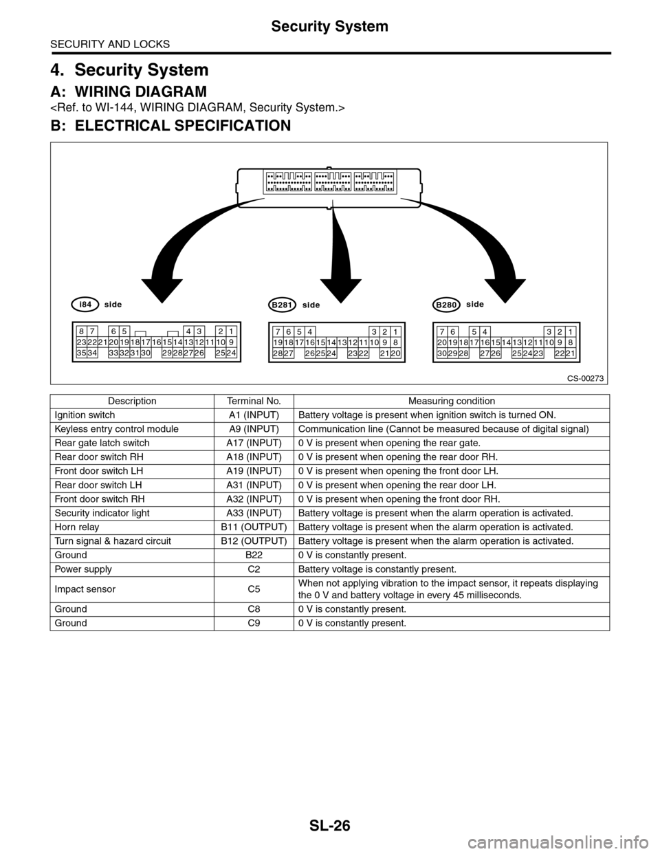
B: ELECTRICAL SPECIFICATION
Description Terminal No. Measuring condition
Ignition switch A1 (INPUT) Battery voltage is present when ignition switch is turned ON.
Keyless entr y control module A9 (INPUT) Communication line (Cannot be measured because of digital signal)
Rear gate latch switch A17 (INPUT) 0 V is present when opening the rear gate.
Rear door switch RH A18 (INPUT) 0 V is present when opening the rear door RH.
Fr o nt d oo r swi tc h L H A 19 ( I NP UT ) 0 V i s pr e se n t wh e n o p en in g th e f r o n t d oo r L H.
Rear door switch LH A31 (INPUT) 0 V is present when opening the rear door LH.
Fr o nt d oo r swi tc h RH A 32 ( I NP UT ) 0 V i s pr e se n t wh e n o p en in g th e f r o n t d oo r RH.
Security indicator light A33 (INPUT) Battery voltage is present when the alarm operation is activated.
Horn relay B11 (OUTPUT) Battery voltage is present when the alarm operation is activated.
Tu r n s i g n a l & h a z a r d c i r c u i t B 1 2 ( O U T P U T ) B a t t e r y v o l t a g e i s p r e s e n t w h e n t h e a l a r m o p e r a t i o n i s a c t i v a t e d .
Ground B22 0 V is constantly present.
Pow er s up p ly C 2 B at t e r y vol t ag e i s c on s ta n tl y p r e se nt .
Impact sensor C5When not applying vibration to the impact sensor, it repeats displaying
the 0 V and battery voltage in every 45 milliseconds.
Ground C8 0 V is constantly present.
Ground C9 0 V is constantly present.
CS-00273
71928
61827
51741626152514241312231122
3102921
1820
B281side
72030
619291828
51741627152614132512241123
3102922
1821
B280side
82335
722342162033
51932183117301615291428
41327
312261121025
1924
i84side
Page 657 of 2453
SL-28
Security System
SECURITY AND LOCKS
CAUTION:
•Security alarm ON/OFF setting
At the time of shipment from the factory, the security alarm is set to “ON”. However, when {Security
setting initialization} is performed with the Subaru Select Monitor, the security alarm automatically is
set to “OFF”. When security initialization has been performed, always return the ON/OFF setting for
the security alarm to “ON”.
•Siren YES/NO setting
The {Siren YES/NO} setting of the item {Unit customization} of the Subaru Select Monitor always
shall be set to “NO”. If it is set to “YES”, the horn of the security alarm will not sound.
7CHECK SECURITY ALARM OPERATION.
1) Unlock all doors using the door lock switch
on driver’s door.
2) Open any door or rear gate.
Does the security alarm oper-
ate when opening any door or
rear gate?
Go to step 8.•Check the door
switch.
DOOR SWITCH,
INSPECTION,
Security System.>
•Check the rear
gate latch switch.
GATE LATCH
SWITCH.,
INSPECTION,
Security System.>
8CHECK SECURITY ALARM OPERATION.
Check the security alarm operation.
Does all of the following secu-
rity alarm operate? •Horn
sounds •Hazard light blinks
•Security indicator light blinks
Go to step 9.•Check horn.
INSPECTION,
Security System.>
•Check the haz-
ard light.
HAZARD LIGHT
OPERATION,
INSPECTION,
Security System.>
9CHECK SECURITY ALARM CANCEL OPER-
ATION.
Press any button of transmitter while operating
security alarm. Or turn the ignition switch
OFF→ON three times.
Does all of the following secu-
rity alarm stop? •Horn •Hazard
light
Go to step 10.Check the ignition
switch circuit.
TION SWITCH
CIRCUIT,
INSPECTION,
Security System.>
10 CHECK SECURITY SYSTEM CONDITION
MEMORY.
Check that the system function properly when
the battery is not connected temporally.
DITION MEMORY, INSPECTION, Security
System.>
Does the system function prop-
erly when the battery is not
connected temporally?
Go to step 11.Replace the body
integrated unit.
Unit.>
11 CHECK IMPACT SENSOR.
Check the sensibility of impact sensor.
MENT, Impact Sensor.>
Is the sensibility set properly? Press the
UNLOCK button of
keyless transmit-
ter, and finish the
diagnosis.
Adjust the sensibil-
ity.
TIVITY ADJUST-
MENT,
ADJUSTMENT,
Impact Sensor.>
Step Check Yes No
Page 678 of 2453
SL-49
Impact Sensor
SECURITY AND LOCKS
20.Impact Sensor
A: REMOVAL
1) Remove the key from ignition switch.
2) Close all doors and the rear gate.
3) Press the UNLOCK button of the keyless trans-
mitter.
4) Change the setting of impact sensor using Sub-
aru Select Monitor.
5) Disconnect the ground cable from battery.
6) Remove the impact sensor.
B: INSTALLATION
1) Remove the key from ignition switch.
2) Close all doors and the rear gate.
3) Press the UNLOCK button of the keyless trans-
mitter.
4) Disconnect the ground cable from battery.
5) Install the impact sensor.
6) Connect the ground cable to the battery.
7) Change the setting of impact sensor using Sub-
aru Select Monitor.
C: OPERATION
1. IMPACT SENSOR SETTING USING SUB-
ARU SELECT MONITOR
1) Connect the Subaru Select Monitor to data link
connector.
2) Turn the ignition switch to ON.
3) Select {Integ. unit} from main menu.
4) Select {ECU customizing}.
5) Make a impact monitor setting.
•When installing: ON
•When removing: OFF
6) Make a impact monitor ON/OFF setting.
•When installing: ON
•When removing: OFF
7) Turn the ignition switch to OFF, and then remove
the Subaru Select Monitor.
D: ADJUSTMENT
1. CHECK IMPACT SENSOR
1) Remove the key from ignition switch.
2) Close all windows.
3) Close all doors and the rear gate. Leave open
the front hood.
4) Press the LOCK button of the keyless transmit-
ter from outside of vehicle.
5) Check that the security indicator light blinks
twice within 0.5 seconds in 2 seconds cycle after 30
seconds.
6) Hit the windshield with your palm continuously
and check the security alarm operates. Lift up the
front hood approx. 12 cm (4.7 in) or more, and then
drop it off to check the operation of security alarm.
7) If NG, adjust the impact sensitivity.
2. IMPACT SENSITIVITY ADJUSTMENT
1) Connect the Subaru Select Monitor to data link
connector.
2) Turn the ignition switch to ON.
3) Select {Impact Sensor} from the main menu.
4) Make a {ECU customizing}.
•Sensitivity can be adjusted in 11 levels (0 to 10).
•Initial setting is 5.
•Smaller number means more sensitive.
•Larger number means less sensitive.
5) Turn the ignition switch to OFF, and then remove
the Subaru Select Monitor.
NOTE:
•Set the sensor so as not to let the alarm on nor-
mal vibration (reclining to the door, hit the ball and
etc.).
•Set the sensor to operate the alarm with hitting
the door or window glass, etc. continuously like a
mayhem by robbery.
•Ask the customer about parking situation for set-
ting, because the alarm operate when the vibration
not only the burglar but also the construction etc.
Page 724 of 2453
BR-10
General Description
BRAKE
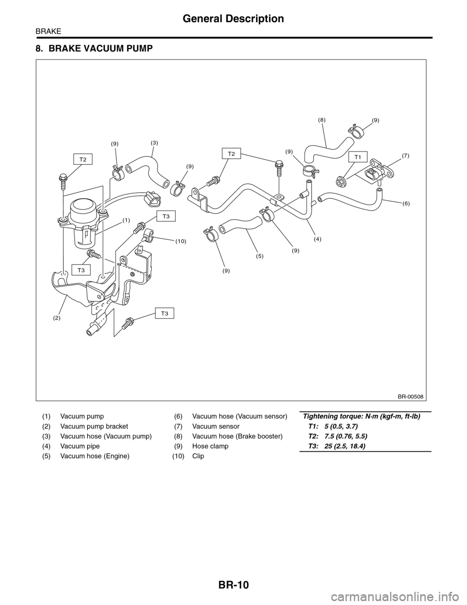
8. BRAKE VACUUM PUMP
(1) Vacuum pump (6) Vacuum hose (Vacuum sensor)Tightening torque: N·m (kgf-m, ft-lb)
(2) Vacuum pump bracket (7) Vacuum sensorT1: 5 (0.5, 3.7)
(3) Vacuum hose (Vacuum pump) (8) Vacuum hose (Brake booster)T2: 7.5 (0.76, 5.5)
(4) Vacuum pipe (9) Hose clampT3: 25 (2.5, 18.4)
(5) Vacuum hose (Engine) (10) Clip
BR-00508
(4)
(9)(5)
(9)
(7)
(6)
(9)(8)
(9)
(9)
(9)
(3)
(1)
(10)
(2)
T2T2
T3
T3
T3
T1
Page 754 of 2453
BR-40
Brake Vacuum Sensor
BRAKE
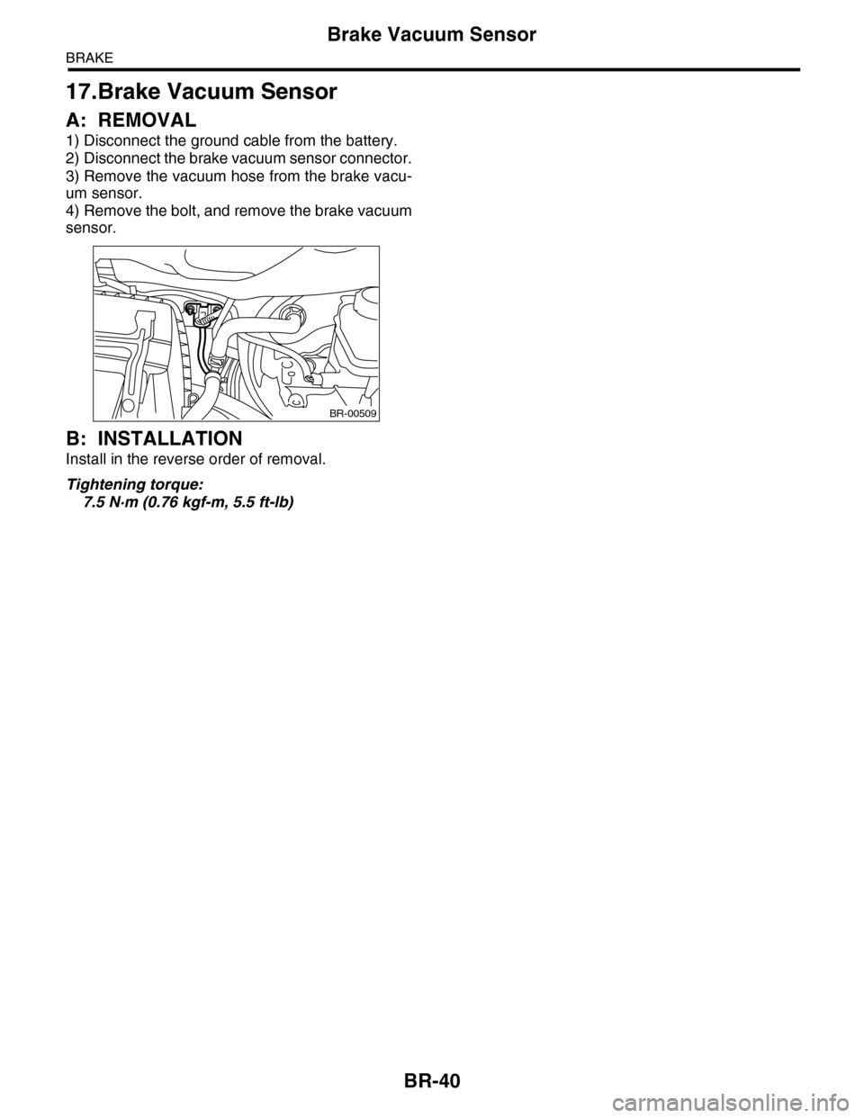
17.Brake Vacuum Sensor
A: REMOVAL
1) Disconnect the ground cable from the battery.
2) Disconnect the brake vacuum sensor connector.
3) Remove the vacuum hose from the brake vacu-
um sensor.
4) Remove the bolt, and remove the brake vacuum
sensor.
B: INSTALLATION
Install in the reverse order of removal.
Tightening torque:
7.5 N·m (0.76 kgf-m, 5.5 ft-lb)
BR-00509
Page 760 of 2453
BVC(diag)-5
General Description
BRAKE VACUUM CONTROL (BVC) (DIAGNOSTICS)
3. General Description
A: CAUTION
1. SRS AIRBAG SYSTEM
Airbag system wiring harness is routed near the ABS wheel speed sensor and VDCCM&H/U.
CAUTION:
•All airbag system wiring harness and connectors are colored yellow. Do not use the electrical test
equipment on these circuits.
•Be careful not to damage the airbag system wiring harness.
B: INSPECTION
Before performing diagnosis, check the following items which might affect the brake vacuum control.
1. BATTERY
Measure the battery voltage and check electrolyte.
Standard voltage: 12 V or more
Specific gravity: 1.260 or more
2. BRAKE VACUUM HOSE
Make sure the brake vacuum hose is not cracked or loose.
C: PREPARATION TOOL
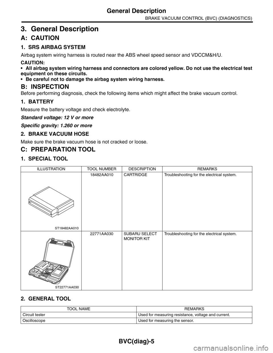
1. SPECIAL TOOL
2. GENERAL TOOL
ILLUSTRATION TOOL NUMBER DESCRIPTION REMARKS
18482AA010 CARTRIDGE Troubleshooting for the electrical system.
22771AA030 SUBARU SELECT
MONITOR KIT
Tr o u b l e s h o o t i n g f o r t h e e l e c t r i c a l s y s t e m .
TOOL NAME REMARKS
Circuit tester Used for measuring resistance, voltage and current.
Oscilloscope Used for measuring the sensor.
ST18482AA010
ST22771AA030
Page 761 of 2453
BVC(diag)-6
Electrical Component Location
BRAKE VACUUM CONTROL (BVC) (DIAGNOSTICS)
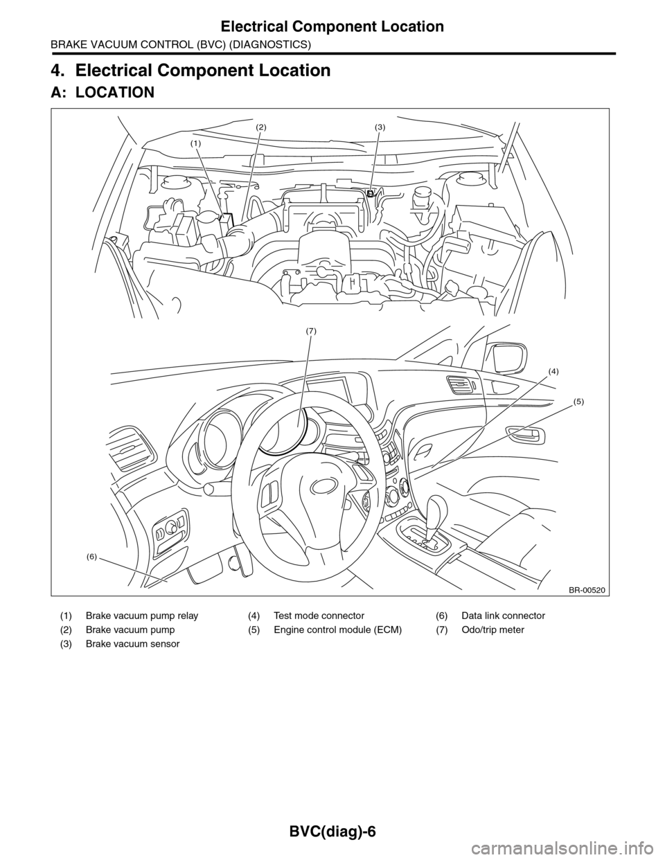
4. Electrical Component Location
A: LOCATION
(1) Brake vacuum pump relay (4) Test mode connector (6) Data link connector
(2) Brake vacuum pump (5) Engine control module (ECM) (7) Odo/trip meter
(3) Brake vacuum sensor
BR-00520
(1)
(2)(3)
(7)
(4)
(5)
(6)
Page 763 of 2453
BVC(diag)-8
Engine Control Module (ECM) I/O Signal
BRAKE VACUUM CONTROL (BVC) (DIAGNOSTICS)
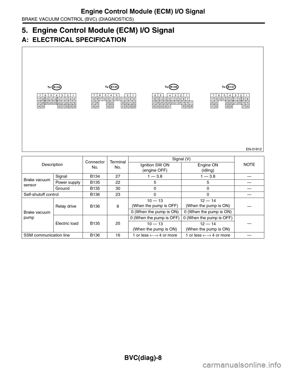
5. Engine Control Module (ECM) I/O Signal
A: ELECTRICAL SPECIFICATION
DescriptionConnector
No.
Te r m i n a l
No.
Signal (V)
NOTEIgnition SW ON
(engine OFF)
Engine ON
(idling)
Brake vacuum
sensor
Signal B134 27 1 — 3.8 1 — 3.8 —
Pow er s up pl y B 1 35 2 2 5 5 —
Ground B135 30 0 0 —
Self-shutoff control B136 23 0 0 —
Brake vacuum
pump
Relay drive B136 8
10 — 13
(When the pump is OFF)
12 — 14
(When the pump is ON)—
0 (When the pump is ON) 0 (When the pump is ON)
Electric load B135 25
0 (When the pump is OFF) 0 (When the pump is OFF)
—10 — 13
(When the pump is ON)
12 — 14
(When the pump is ON)
SSM communication line B136 16 1 or less ←→ 4 or more 1 or less ←→ 4 or more —
EN-01812
B134
5678219431024 2223251112131415262728
1617181920213334 2932 3031
B136
5678219431024 2223251112131415262728
16171819202133342932303135
B135
5678219431024 2223251112131415262728
16171819202129303132333435
B137
5678219431022231112131415242526
1617181920212728293031
ToToToTo