sensor SUBARU TRIBECA 2009 1.G Service Workshop Manual
[x] Cancel search | Manufacturer: SUBARU, Model Year: 2009, Model line: TRIBECA, Model: SUBARU TRIBECA 2009 1.GPages: 2453, PDF Size: 46.32 MB
Page 585 of 2453
OD(diag)-17
Subaru Select Monitor
OCCUPANT DETECTION SYSTEM (DIAGNOSTICS)
7. Subaru Select Monitor
A: OPERATION
1. READ DIAGNOSTIC TROUBLE CODE (DTC)
When malfunction of the airbag system and the occupant detection system occur, the DTC stored in airbag
control module will be read out.
Refer to the DTC readout of the airbag system (diagnosis).
NOTE:
•For details concerning operation procedure, refer to the “SUBARU SELECT MONITOR OPERATION
MANUAL”.
•For details concerning DTCs, refer to the “List of Diagnostic Trouble Code (Airbag system, Occupant de-
tection system).”
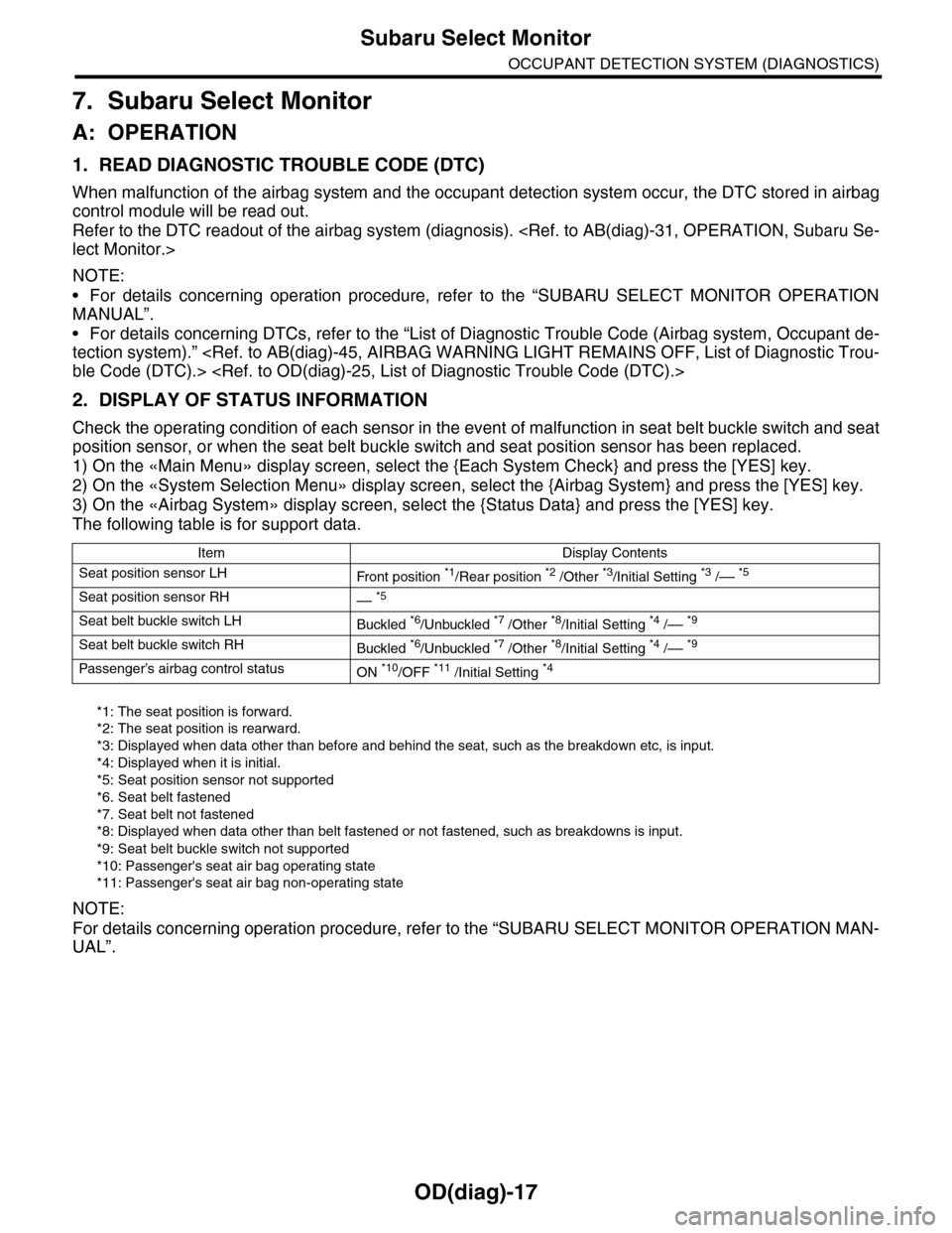
2. DISPLAY OF STATUS INFORMATION
Check the operating condition of each sensor in the event of malfunction in seat belt buckle switch and seat
position sensor, or when the seat belt buckle switch and seat position sensor has been replaced.
1) On the «Main Menu» display screen, select the {Each System Check} and press the [YES] key.
2) On the «System Selection Menu» display screen, select the {Airbag System} and press the [YES] key.
3) On the «Airbag System» display screen, select the {Status Data} and press the [YES] key.
The following table is for support data.
*1: The seat position is forward.
*2: The seat position is rearward.
*3: Displayed when data other than before and behind the seat, such as the breakdown etc, is input.
*4: Displayed when it is initial.
*5: Seat position sensor not supported
*6. Seat belt fastened
*7. Seat belt not fastened
*8: Displayed when data other than belt fastened or not fastened, such as breakdowns is input.
*9: Seat belt buckle switch not supported
*10: Passenger's seat air bag operating state
*11: Passenger's seat air bag non-operating state
NOTE:
For details concerning operation procedure, refer to the “SUBARU SELECT MONITOR OPERATION MAN-
UAL”.
Item Display Contents
Seat position sensor LHFr o nt p os it i on *1/Rear position *2 /Other *3/Initial Setting *3 /–– *5
Seat position sensor RH–– *5
Seat belt buckle switch LHBuckled *6/Unbuckled *7 /Other *8/Initial Setting *4 /–– *9
Seat belt buckle switch RHBuckled *6/Unbuckled *7 /Other *8/Initial Setting *4 /–– *9
Passenger’s airbag control statusON *10/OFF *11 /Initial Setting *4
Page 593 of 2453
OD(diag)-25
List of Diagnostic Trouble Code (DTC)
OCCUPANT DETECTION SYSTEM (DIAGNOSTICS)
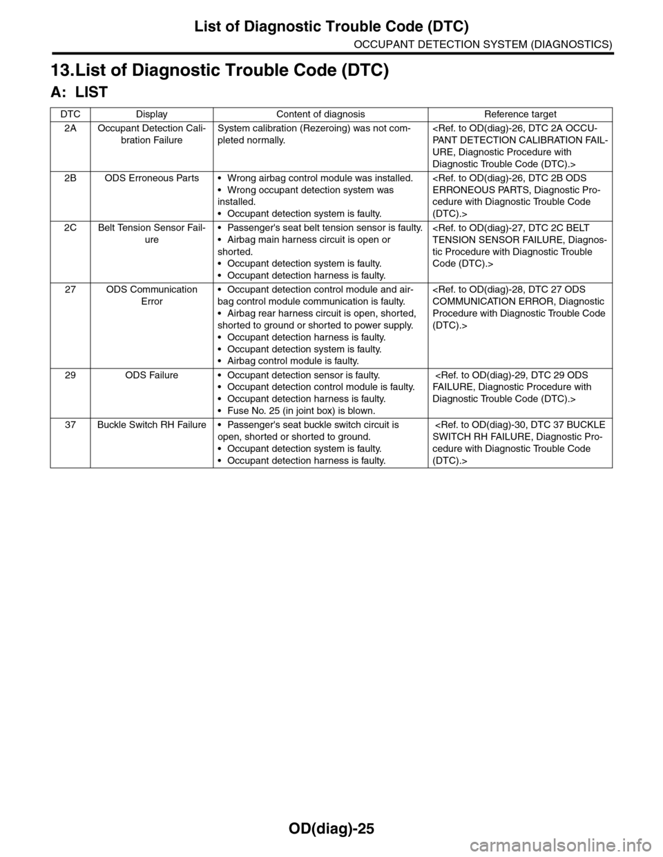
13.List of Diagnostic Trouble Code (DTC)
A: LIST
DTC Display Content of diagnosis Reference target
2A Occupant Detection Cali-
bration Failure
System calibration (Rezeroing) was not com-
pleted normally.
URE, Diagnostic Procedure with
Diagnostic Trouble Code (DTC).>
2B ODS Erroneous Parts • Wrong airbag control module was installed.
•Wrong occupant detection system was
installed.
•Occupant detection system is faulty.
cedure with Diagnostic Trouble Code
(DTC).>
2C Belt Tension Sensor Fail-
ure
•Passenger's seat belt tension sensor is faulty.
•Airbag main harness circuit is open or
shorted.
•Occupant detection system is faulty.
•Occupant detection harness is faulty.
tic Procedure with Diagnostic Trouble
Code (DTC).>
27 ODS Communication
Error
•Occupant detection control module and air-
bag control module communication is faulty.
•Airbag rear harness circuit is open, shorted,
shorted to ground or shorted to power supply.
•Occupant detection harness is faulty.
•Occupant detection system is faulty.
•Airbag control module is faulty.
Procedure with Diagnostic Trouble Code
(DTC).>
29 ODS Failure • Occupant detection sensor is faulty.
•Occupant detection control module is faulty.
•Occupant detection harness is faulty.
•Fuse No. 25 (in joint box) is blown.
Diagnostic Trouble Code (DTC).>
37 Buckle Switch RH Failure • Passenger's seat buckle switch circuit is
open, shorted or shorted to ground.
•Occupant detection system is faulty.
•Occupant detection harness is faulty.
cedure with Diagnostic Trouble Code
(DTC).>
Page 595 of 2453
OD(diag)-27
Diagnostic Procedure with Diagnostic Trouble Code (DTC)
OCCUPANT DETECTION SYSTEM (DIAGNOSTICS)
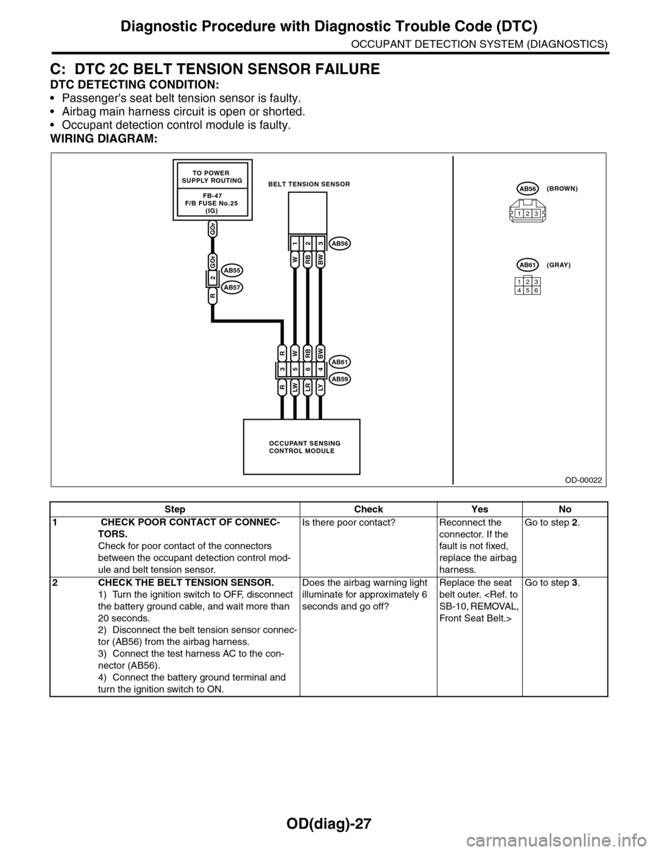
C: DTC 2C BELT TENSION SENSOR FAILURE
DTC DETECTING CONDITION:
•Passenger's seat belt tension sensor is faulty.
•Airbag main harness circuit is open or shorted.
•Occupant detection control module is faulty.
WIRING DIAGRAM:
OD-00022
GOr
FB-47F/B FUSE No.25 (IG)
TO POWER SUPPLY ROUTING
OCCUPANT SENSINGCONTROL MODULE
BELT TENSION SENSOR
3
R
R
5
LW
W
6
LR
RB
4
LY
BW
123
WRBBW
AB61
AB59
AB56
123456
AB61(GRAY)
AB56(BROWN)
123
2
GOr
R
AB55
AB57
Step Check Yes No
1 CHECK POOR CONTACT OF CONNEC-
TORS.
Check for poor contact of the connectors
between the occupant detection control mod-
ule and belt tension sensor.
Is there poor contact? Reconnect the
connector. If the
fault is not fixed,
replace the airbag
harness.
Go to step 2.
2CHECK THE BELT TENSION SENSOR.
1) Turn the ignition switch to OFF, disconnect
the battery ground cable, and wait more than
20 seconds.
2) Disconnect the belt tension sensor connec-
tor (AB56) from the airbag harness.
3) Connect the test harness AC to the con-
nector (AB56).
4) Connect the battery ground terminal and
turn the ignition switch to ON.
Does the airbag warning light
illuminate for approximately 6
seconds and go off?
Replace the seat
belt outer.
Front Seat Belt.>
Go to step 3.
Page 596 of 2453
OD(diag)-28
Diagnostic Procedure with Diagnostic Trouble Code (DTC)
OCCUPANT DETECTION SYSTEM (DIAGNOSTICS)
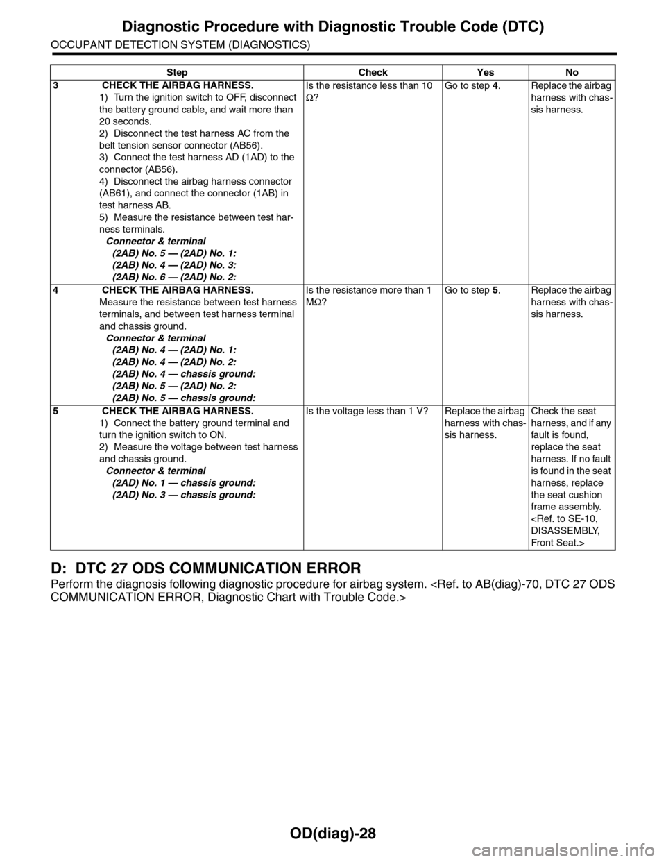
D: DTC 27 ODS COMMUNICATION ERROR
Perform the diagnosis following diagnostic procedure for airbag system.
3 CHECK THE AIRBAG HARNESS.
1) Turn the ignition switch to OFF, disconnect
the battery ground cable, and wait more than
20 seconds.
2) Disconnect the test harness AC from the
belt tension sensor connector (AB56).
3) Connect the test harness AD (1AD) to the
connector (AB56).
4) Disconnect the airbag harness connector
(AB61), and connect the connector (1AB) in
test harness AB.
5) Measure the resistance between test har-
ness terminals.
Connector & terminal
(2AB) No. 5 — (2AD) No. 1:
(2AB) No. 4 — (2AD) No. 3:
(2AB) No. 6 — (2AD) No. 2:
Is the resistance less than 10
Ω?
Go to step 4.Replace the airbag
harness with chas-
sis harness.
4 CHECK THE AIRBAG HARNESS.
Measure the resistance between test harness
terminals, and between test harness terminal
and chassis ground.
Connector & terminal
(2AB) No. 4 — (2AD) No. 1:
(2AB) No. 4 — (2AD) No. 2:
(2AB) No. 4 — chassis ground:
(2AB) No. 5 — (2AD) No. 2:
(2AB) No. 5 — chassis ground:
Is the resistance more than 1
MΩ?
Go to step 5.Replace the airbag
harness with chas-
sis harness.
5 CHECK THE AIRBAG HARNESS.
1) Connect the battery ground terminal and
turn the ignition switch to ON.
2) Measure the voltage between test harness
and chassis ground.
Connector & terminal
(2AD) No. 1 — chassis ground:
(2AD) No. 3 — chassis ground:
Is the voltage less than 1 V? Replace the airbag
harness with chas-
sis harness.
Check the seat
harness, and if any
fault is found,
replace the seat
harness. If no fault
is found in the seat
harness, replace
the seat cushion
frame assembly.
Fr o nt S ea t . >
Step Check Yes No
Page 597 of 2453
OD(diag)-29
Diagnostic Procedure with Diagnostic Trouble Code (DTC)
OCCUPANT DETECTION SYSTEM (DIAGNOSTICS)
E: DTC 29 ODS FAILURE
DTC DETECTING CONDITION:
•Occupant detection sensor is faulty.
•Occupant detection control module is faulty.
•Occupant detection harness is faulty.
•Rear airbag harness is faulty.
•Fuse No. 25 (in joint box) is blown.
Step Check Yes No
1 CHECK POOR CONTACT OF CONNEC-
TORS.
Check for poor contact of the connectors
between the occupant detection control mod-
ule and airbag control module.
Is there poor contact? Reconnect the
connector. If the
fault is not fixed,
replace the airbag
harness.
Go to step 2.
2 CHECK DIAGNOSTIC TROUBLE CODE
(DTC).
READ DIAGNOSTIC TROUBLE CODE (DTC)
FOR THE AIRBAG SYSTEM.
Is “2C Belt Tension Sensor fail-
ure or 37 Buckle Switch failure”
displayed in the diagnostics
code?
Pe r for m t h e d ia g -
nosis according to
each DTC.
Check the seat
harness, and if any
fault is found,
replace the seat
harness. If the
fault is not fixed,
replace the occu-
pant detection sys-
tem.
BLY, Front Seat.>
Page 599 of 2453
SB-2
General Description
SEAT BELT SYSTEM
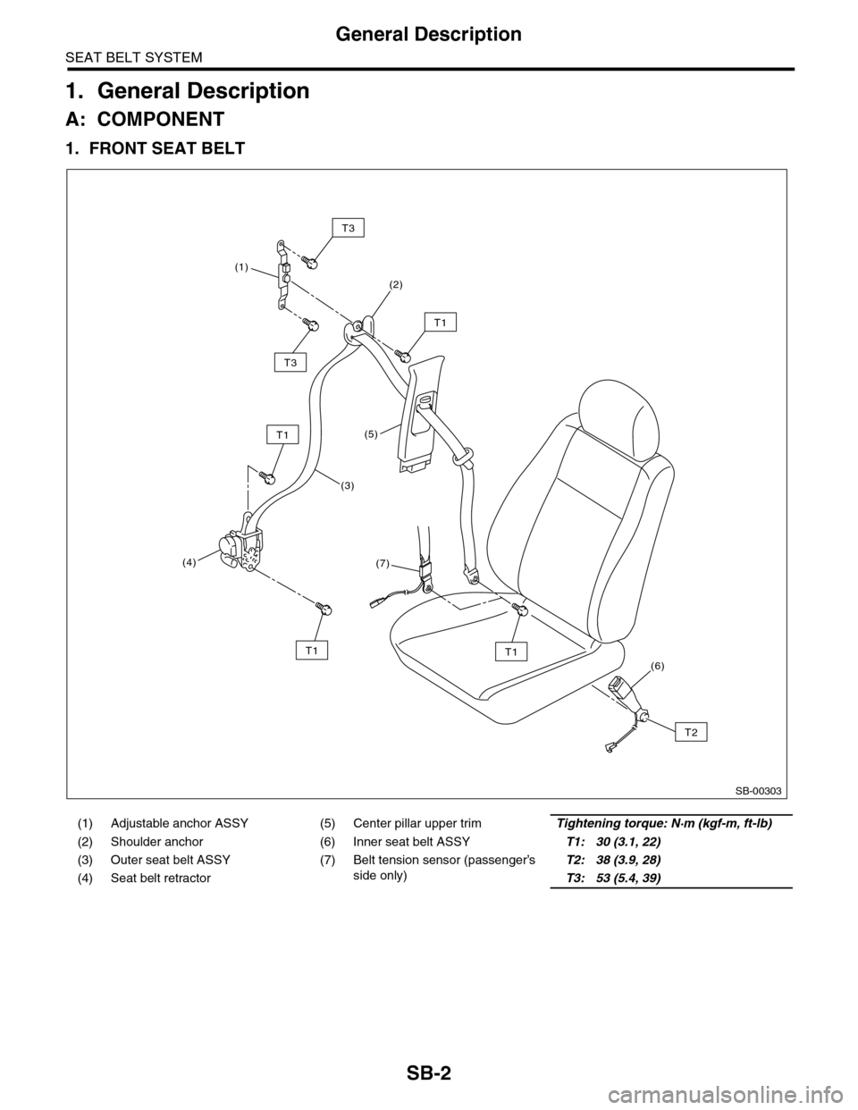
1. General Description
A: COMPONENT
1. FRONT SEAT BELT
(1) Adjustable anchor ASSY (5) Center pillar upper trimTightening torque: N·m (kgf-m, ft-lb)
(2) Shoulder anchor (6) Inner seat belt ASSYT1: 30 (3.1, 22)
(3) Outer seat belt ASSY (7) Belt tension sensor (passenger’s
side only)
T2: 38 (3.9, 28)
(4) Seat belt retractorT3: 53 (5.4, 39)
SB-00303
(6)
T2
T1
T1
T3
(3)
(7)(4)
(5)
(2)
T1
(1)
T1
T3
Page 607 of 2453
SB-10
Front Seat Belt
SEAT BELT SYSTEM
5. Front Seat Belt
A: REMOVAL
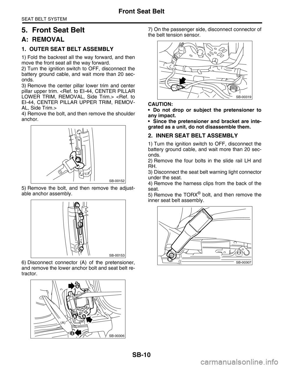
1. OUTER SEAT BELT ASSEMBLY
1) Fold the backrest all the way forward, and then
move the front seat all the way forward.
2) Turn the ignition switch to OFF, disconnect the
battery ground cable, and wait more than 20 sec-
onds.
3) Remove the center pillar lower trim and center
pillar upper trim.
AL, Side Trim.>
4) Remove the bolt, and then remove the shoulder
anchor.
5) Remove the bolt, and then remove the adjust-
able anchor assembly.
6) Disconnect connector (A) of the pretensioner,
and remove the lower anchor bolt and seat belt re-
tractor.
7) On the passenger side, disconnect connector of
the belt tension sensor.
CAUTION:
•Do not drop or subject the pretensioner to
any impact.
•Since the pretensioner and bracket are inte-
grated as a unit, do not disassemble them.
2. INNER SEAT BELT ASSEMBLY
1) Turn the ignition switch to OFF, disconnect the
battery ground cable, and wait more than 20 sec-
onds.
2) Remove the four bolts in the slide rail LH and
RH.
3) Disconnect the seat belt warning light connector
under the seat.
4) Remove the harness clips from the back of the
seat.
5) Remove the TORX® bolt, and then remove the
inner seat belt assembly.
SB-00152
SB-00153
SB-00306
(A)
SB-00319
SB-00307
Page 608 of 2453
SB-11
Front Seat Belt
SEAT BELT SYSTEM
B: INSTALLATION
1. OUTER SEAT BELT ASSEMBLY
Install in the reverse order of removal.
CAUTION:
•The parts of driver and passenger sides are
not the same. Before installation, make sure
that the correct part is used.
•Be careful not to twist the seat belts during
installation.
Tightening torque:
2. INNER SEAT BELT ASSEMBLY
Install in the reverse order of removal.
CAUTION:
•After the driver’s and passenger’s inner seat
belt assembly installation, check that the seat
belt buckle switch operates normally using the
Subaru Select Monitor in {Status Data} of “Air-
bag System”.
aru Select Monitor.>Improper buckle switch op-
eration may cause airbag system malfunction.
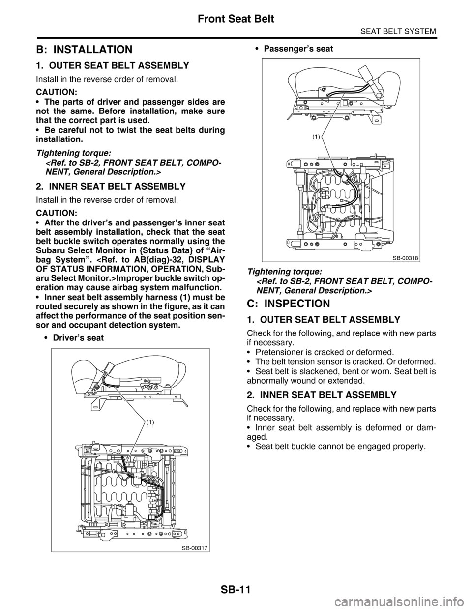
•Inner seat belt assembly harness (1) must be
routed securely as shown in the figure, as it can
affect the performance of the seat position sen-
sor and occupant detection system.
•Driver’s seat
•Passenger’s seat
Tightening torque:
C: INSPECTION
1. OUTER SEAT BELT ASSEMBLY
Check for the following, and replace with new parts
if necessary.
•Pretensioner is cracked or deformed.
•The belt tension sensor is cracked. Or deformed.
•Seat belt is slackened, bent or worn. Seat belt is
abnormally wound or extended.
2. INNER SEAT BELT ASSEMBLY
Check for the following, and replace with new parts
if necessary.
•Inner seat belt assembly is deformed or dam-
aged.
•Seat belt buckle cannot be engaged properly.
SB-00317
(1)
SB-00318
(1)
Page 616 of 2453
SE-6
General Description
SEATS
B: CAUTION
•If the seat cushion cover is removed or replaced, make sure to perform passenger detection system ad-
justment after installing the seat to the vehicle.
Failure to do so may cause improper operation of the passenger detection system.
•The passenger detection system (passenger seat only) control unit and the passenger detection sensor
are fixed to the seat cushion frame. Never remove the passenger detection control unit or the pressure sen-
sor from the seat cushion frame.
•Do not replace the seat cushion pad by itself. Always replace the seat cushion pad and frame assembly
as a set. The seat cushion pad and cushion frame are adjusted as a set at the time of manufacture. If cushion
pads and cushion frames are combined from those of other vehicles or other sets, the passenger detection
system may not operate properly.
•If the seat cushion cover is removed, make sure to replace the wire on the seat cushion side with a new
wire.
•When removing the front seat from a side airbag loaded vehicle, follow cautions given in the airbag section.
C: PREPARATION TOOL
1. GENERAL TOOL
TOOL NAME REMARKS
Long nose plier Used for removing the hog ring.
Hog ring pliers Used for installing the hog ring.
TO RX® T50Used for removing/installing inner seat belt assembly and
removing/installing/disassembling second-row seats.
Page 617 of 2453
SE-7
Front Seat
SEATS
2. Front Seat
A: REMOVAL
CAUTION:
The airbag system is fitted with a backup power
source. After disconnecting the battery ground
cable, the airbag may deploy if you do not wait
for 20 seconds before starting the service of
airbag system.
1. DRIVER’S SEAT
1) Remove the headrest.
2) Tilt the backrest forward, and move the seat for-
ward.
3) Remove the rear leg cover, and remove the two
bolts at the rear side of slide rail.
4) Move the seat backward, remove the front leg
cover, and then remove the 2 bolts at the front side
of the slide rail.
5) Disconnect the ground cable from battery, and
wait for more than 20 seconds before starting work.
6) Disconnect the connector under the seat.
•Seat belt buckle switch connector
•Seat position sensor connector
•Side airbag connector
•Seat heater connector
•Power seat connector
7) Remove the seat from vehicle.
2. PASSENGER’S SEAT
CAUTION:
Refer to “CAUTION” of “General Description”
before starting the work.
1) Remove the headrest.
2) Tilt the backrest forward, and move the seat for-
ward.
3) Remove the rear leg cover, and remove the bolt
at the rear side of the slide rail.
4) Move the seat backward, remove the front leg
cover, and then remove the bolt at the front side of
the slide rail.
5) Disconnect the ground cable from battery, and
wait for more than 20 seconds before starting work.
6) Disconnect all the connectors of connector hold-
er in the backside of seat cushion.
•Harness connector of occupant detection control
module
•Side airbag connector
•Power seat connector
•Seat heater connector
7) Remove the seat belt anchor cover.
NOTE:
Tilt the seat back all the way to provide workspace.
8) Remove the seat from vehicle.
B: INSTALLATION
Install in the reverse order of removal.
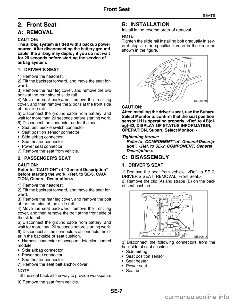
NOTE:
Tighten the slide rail installing bolt gradually in sev-
eral steps to the specified torque in the order as
shown in the figure.
CAUTION:
After installing the driver’s seat, use the Subaru
Select Monitor to confirm that the seat position
sensor LH is operating properly.
OPERATION, Subaru Select Monitor.>
Tightening torque:
Refer to “COMPONENT” of “General Descrip-
tion”.
C: DISASSEMBLY
1. DRIVER’S SEAT
1) Remove the seat from vehicle.
2) Remove the clip (A) and straps (B) on the back
of seat cushion.
3) Disconnect the following connectors from the
backside of seat cushion.
•Side airbag
•Seat position sensor
•Seat heater
•Power seat
•Seat belt
SE-00479
(1)
(3)
(4)
(2)
(B)(A)
SE-00643