SUZUKI GRAND VITARA 1987 Service Workshop Manual
Manufacturer: SUZUKI, Model Year: 1987, Model line: GRAND VITARA, Model: SUZUKI GRAND VITARA 1987Pages: 962, PDF Size: 27.87 MB
Page 51 of 962

Condition
Excessive pedal travel
(Pedal stroke too
large)
Possible cause
1. Partial brake system failure
2. Insufficient fluid in master
cylinder reservoirs
Correction
Check diagonal brake systems and
repair as necessary
Fill reservoirs with approved brake
fluid. Check for leaks and air in
brake systems. Check warning light.
Bleed system if necessary.
3. Air in system (Pedal soft/spongy)Bleed system
4. Rear brake system not adjustedAdjust rear brakes (Repair auto
(malfunctioning auto adjustingadjusting mechanism)
mechanism)
5. Bent brake shoesReplace brake shoes
6. Worn rear brake shoesReplace brake shoes.
Dragging brakes (A
very light drag is pre-
sent in all disc brakes
immediately after
pedal is released)
1. Master cylinder pistons not
returning correctly
2. Clogged return port in master
cylinder
3. Restricted brake tubes or hoses
4. Incorrect parking brake
adjustment
5. Weakened or broken return
springs in the brake
Repair master cylinder
Clean
Check for soft hoses or damaged tubes
and replace with new hoses and/or
new double-walled steel brake tubing
Check and adjust to correct specifica-
tions
Replace
6. Sluggish parking-brake cables or
linkage
Repair or replace
7. Wheel cylinder or caliper piston
sticking
Repair as necessary
Pedal pulsation1. Damaged or loose wheel bearingsReplace wheel bearings
(Pedal pulsates when2. Excessive disc lateral runout Check per instructions. If not within
depressed for braking)specifications, replace or machine the
disc.
3. Parallelism not within specifica-Check per instructions. If not within
tionsspecifications, replace or machine the
disc.
4. Rear drums out of roundCheck runout.
Braking noise1. Glazed shoe linings, or foreignRepair or replace shoe lining
matters stuck to linings
2. Worn or distorted shoe liningsReplace shoe lining (or pad)
3. Loose front wheel bearingsReplace wheel bearings
4. Distorted backing plates or looseReplace or retighten securing bolts
mounting bolts
2-13
Page 52 of 962

2-9. SUSPENSION, STEERING SYSTEM AND TIRES
Condition
Hard steering
Possible causeCorrection
1. Wheel tires not adequately inflatedAdjust the pressure
2. Bind in tie rod end ball studReplace
3. Linkage connections tending to seizeRepair or replace
4. Steering gearbox out of adjustmentAdjust as prescribed
5. Unevenly worn steering shaft bushReplace
6. Disturbed front wheel alignmentAdjust as prescribed
Wobbly steering wheel1. Wheel tires inflated unequallyAdjust tire pressure
(Shimmy, shake or2. Wobbly wheelsRepair or replace
vibration)3. Large difference in tire diameter betweenReplace._
right and left wheels
4. Loose hub nutsRetighten
5. Damaged or worn wheel bearingsReplace
6. Worn or loose tie rod endsReplace or retighten
7. Steering gearbox out of adjustmentAdjust as prescribed
8. Steering gearbox mounted looseRetighten
9. Worn steering knuckle oil sealReplace
10. Tire or wheel out of balanceBalance wheel or replace tire
and/or wheel
11. Blister or bump on tireReplace tire
12. Disturbed front wheel alignmentCheck front wheel alignment
Steering wheel
pulling to one
side (car pulls)
1. Unevenly worn wheel tires
2. Brake dragging in one road wheel
3. Wheel tires unequally inflated
4. Worn or distorted link rods
5. Disturbed front wheel alignment
6. Loose, bent or broken front or rear
suspension parts
Replace
Repair
Adjust tire pressure
Replace
Adjust as prescribed
Tighten or replace suspension
parts
Shocks coming to1. Tire inflating pressure too highReduce to the specification
steering wheel2. Poor shock absorber performanceReplace
(or wheel tramp)3. Differences in tire diameter among fourAdjust
road wheels
4. Worn steering linkage connectionsReplace
5. Worn or broken front wheel bearingsReplace
6. Loose front wheelRetighten
7. Steering wheel loose in placeRetighten the nut
8. Blister or bump on tireReplace tire
Rapid wear or uneven1. Wheel tires imporperly inflatedAdjust tire pressure
wear of wheel tires2. Differences in diameter among four tiresAdjust or replace
(Abnormal or excessive3. Worn or loose road wheel bearingsReplace
tire wear)4. Wobbly wheel tiresRepair or replace
2-14
Page 53 of 962
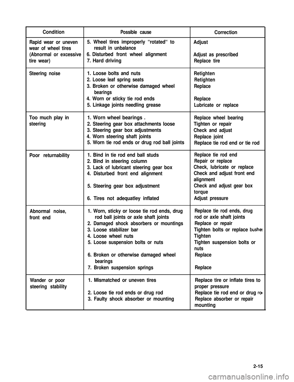
ConditionPossible causeCorrection
Rapid wear or uneven5. Wheel tires improperly “rotated“ toAdjust
wear of wheel tiresresult in unbalance
(Abnormal or excessive6. Disturbed front wheel alignmentAdjust as prescribed
tire wear)7. Hard drivingReplace tire
Steering noise1. Loose bolts and nuts
2. Loose leaf spring seats
3. Broken or otherwise damaged wheel
bearings
4. Worn or sticky tie rod ends
5. Linkage joints needling grease
Retighten
Retighten
Replace
Replace
Lubricate or replace
Too much play in
steering
1. Worn wheel bearings .Replace wheel bearing
2. Steering gear box attachments looseTighten or repair
3. Steering gear box adjustmentsCheck and adjust
4. Worn steering shaft jointsReplace joint
5. Worn tie rod ends or drug rod ball jointsReplace tie rod end or tie rod
Poor returnability1. Bind in tie rod end ball studs
2. Bind in steering column
3. Lack of lubricant steering gear box
4. Disturbed front end alignment
5. Steering gear box adjustment
6. Tires not adequatley inflated
Replace tie rod end
Repair or replace
Check, lubricate or replace
Check and adjust front end
alignment
Check and adjust gear box
torque
Adjust pressure
Abnormal noise,
front end
1. Worn, sticky or loose tie rod ends, drug
rod ball joints or axle shaft joints
2. Damaged shock absorbers or mountings
3. Loose stabilizer bar
4. Loose wheel nuts
5. Loose suspension bolts or nuts
6. Broken or otherwise damaged wheel
bearings
7. Broken suspension springs
Replace tie rod ends, drug
rod or axle shaft joints
Replace or repair
Tighten bolts or replace bushe!
Tighten
Tighten suspension bolts or
nuts
Replace
Replace
Wander or poor
steering stability
1. Mismatched or uneven tires
2. Loose tie rod ends or drug rod
3. Faulty shock absorber or mounting
Replace tire or inflate tires to
proper pressure
Replace tie rod end or drug ro(
Replace absorber or repair
mounting
2-15
Page 54 of 962
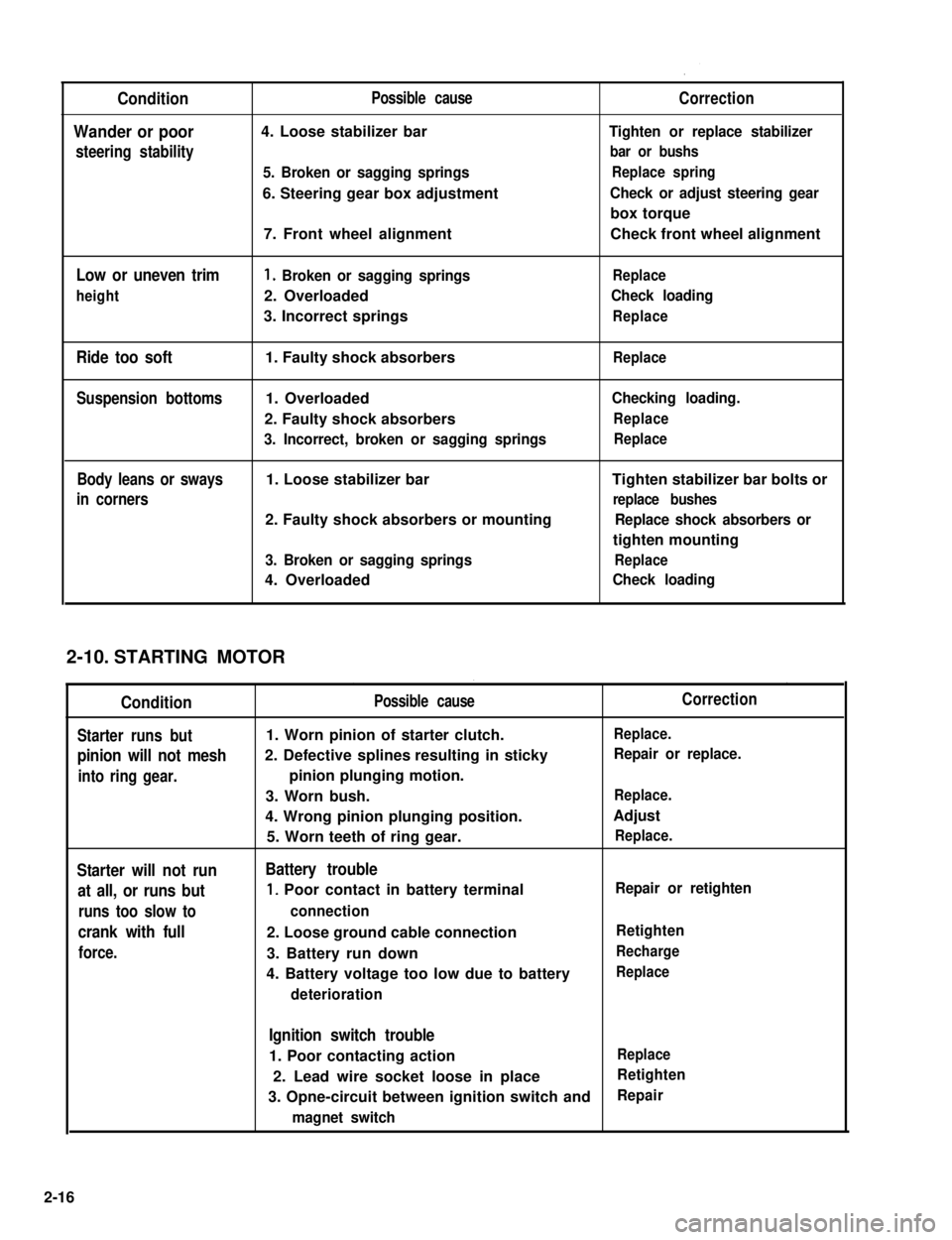
Condition
Wander or poor
steering stability
Low or uneven trim
height
Ride too soft
Suspension bottoms
Body leans or sways
in corners
Possible cause
4. Loose stabilizer bar
5. Broken or sagging springs
6. Steering gear box adjustment
7. Front wheel alignment
1. Broken or sagging springs
2. Overloaded
3. Incorrect springs
1. Faulty shock absorbers
1. Overloaded
2. Faulty shock absorbers
3. Incorrect, broken or sagging springs
1. Loose stabilizer bar
2. Faulty shock absorbers or mounting
3. Broken or sagging springs
4. Overloaded
Correction
Tighten or replace stabilizer
bar or bushs
Replace spring
Check or adjust steering gear
box torque
Check front wheel alignment
Replace
Check loading
Replace
Replace
Checking loading.
Replace
Replace
Tighten stabilizer bar bolts or
replace bushes
Replace shock absorbers or
tighten mounting
Replace
Check loading
STARTING MOTOR
Condition
Starter runs but
pinion will not mesh
into ring gear.
Starter will not run
at all, or runs but
runs too slow to
crank with full
force.
Possible cause
1. Worn pinion of starter clutch.
2. Defective splines resulting in sticky
pinion plunging motion.
3. Worn bush.
4. Wrong pinion plunging position.
5. Worn teeth of ring gear.
Battery trouble
1, Poor contact in battery terminal
connection
2. Loose ground cable connection
3. Battery run down
4. Battery voltage too low due to battery
deterioration
Correction
Replace.
Repair or replace.
Replace.
Adjust
Replace.
Repair or retighten
Retighten
Recharge
Replace
Ignition switch trouble
1. Poor contacting actionReplace
2. Lead wire socket loose in placeRetighten
3. Opne-circuit between ignition switch andRepair
magnet switch
2-10.
2-16
Page 55 of 962
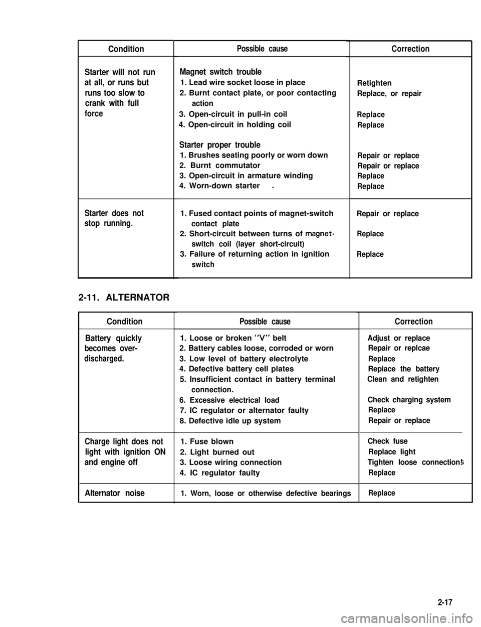
Condition
Starter will not run
at all, or runs but
runs too slow to
crank with full
force
Starter does not
stop running.
2-11. ALTERNATOR
Condition
Battery quickly
becomes over-
discharged.
Charge light does not
light with ignition ON
and engine off
Alternator noise
Possible cause
Magnet switch trouble
1. Lead wire socket loose in place
2. Burnt contact plate, or poor contacting
action
3. Open-circuit in pull-in coil
4. Open-circuit in holding coil
Starter proper trouble
1. Brushes seating poorly or worn down
2. Burnt commutator
3. Open-circuit in armature winding
4. Worn-down starter.
1. Fused contact points of magnet-switch
contact plate
2. Short-circuit between turns of magnet-
switch coil (layer short-circuit)
3. Failure of returning action in ignition
switch
Possible cause
1. Loose or broken “V” belt
2. Battery cables loose, corroded or worn
3. Low level of battery electrolyte
4. Defective battery cell plates
5. Insufficient contact in battery terminal
connection.
6. Excessive electrical load
7. IC regulator or alternator faulty
8. Defective idle up system
1. Fuse blown
2. Light burned out
3. Loose wiring connection
4. IC regulator faulty
1. Worn, loose or otherwise defective bearings
Correction
Retighten
Replace, or repair
Replace
Replace
Repair or replace
Repair or replace
Replace
Replace
Repair or replace
Replace
Replace
Correction
Adjust or replace
Repair or replcae
Replace
Replace the battery
Clean and retighten
Check charging system
Replace
Repair or replace
Check fuse
Replace light
Tighten loose connection!
Replace
i
Replace
2-17
Page 56 of 962

2-12. WIPER MOTOR
Condition
Wiper will not run
Wiper will not stop
running
Wiper stops at
wrong position
Poor wiping action
Possible causeCorrection
1. Fuse set loose or blown offTighten or replace
2. Incomplete metal-to-metal contact in con-
nector.
Repair
3. Worn or floating brushesReplace or repair
4. Dirty or burnt commutatorRepair or replace
5. Short-circuited or fused field coilReplace
6. Loose terminal connection on wiper switchRepair
1. Defective wiper switchRepair or replace
.
1. Improper wiper arm settingRepair
2. Cover plate incorrectly positioned in plcaeRepair
1. Insufficient pressure of wiper armReplace
2. Deteriorated or hardened bladeReplace
3. Blade improperly setRepair or replace
4. Windshield dirty with oilClean
2-13. FUEL METER
Condition
Faulty meter
indication
No indication
Possible cause
1. Incomplete metal-to-metal contact in
terminal connections
2. Defective receiver gauge due to burnt point
or deformed bimetal element
3. Erratic float movement
4. Defective grounding (for float and gauge)
1. Open-circuit
2. Open-circuited heat wire
3. Burnt point
4. Deformed bimetal element
5. Open-circuited resistor
Correction
Retighten
Replace
Repair or replace
Repair
Repair
Replace
Replace
Replace
Replace
2-18
Page 57 of 962

2-14. SPEEDOMETER
IConditionIPossible causeICorrection
Faulty indication1. Damaged speedometer drive or driven gear
2. Defective drive cable
3. Drive cable incompletely or imporperly
tied into the meter
4. Defective speedometer
Replace
Replace
Set right
Replace
Speedometer noise1. Inadequately lubricated or defective cable
2. Not enough oil in transfer
Lubricate or replace
Replenish
2-15. WATER TEMPERATURE METER
Condition
Faulty indication
No indication
Possible cause
1. Incomplete metal-to-metal contact in
terminal connections
2. Receiver gauge defective (due to burnt
point or deformed bimetal element)
3. Defective temperature gauge
1. Open-circuit
2. Defective receiver gauge (open-circuited
heat wire, deformed bimetal element or
pointer)
Repair
Replace
3. Defective temperature gaugeReplace
Correction
Repair and tighten
Replace
Replace
2-19
Page 58 of 962

3-1.
3-2.
3-3.
3-5.
3-6.
3-7.
3-8.
3-9.
SECTION 3
ENGINE
CONTENTS
GENERAL DESCRIPTION.................................... 3-2
ENGINE SERVICES NOT REQUIRING ENGINE REMOVAL...... 3-5
ENGINE REMOVAL.......................................3-6
ENGINE DISASSEMBLY.................................. 3-9
INSPECTION OF ENGINE COMPONENTS....................3-17
ENGINE REASSEMBLY...................................3-35
ENGINE INSTALLATION.................................3-53
ENGINE MAINTENANCE SERVICE.........................3-53
RECOMMENDED TORQUE SPECIFICATIONS.................3-58
3-4.
3-1
3
Page 59 of 962
3-1. GENERAL DESCRIPTION
1) Engine
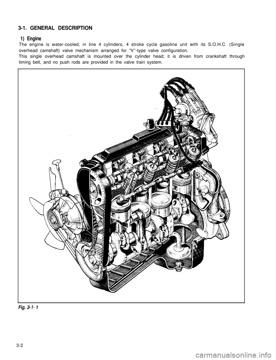
The engine is water-cooled, in line 4 cylinders, 4 stroke cycle gasoline unit with its S.O.H.C (Single
overhead camshaft) valve mechanism arranged for “V’‘-type valve configuration.
This single overhead camshaft is mounted over the cylinder head; it is driven from crankshaft through
timing belt, and no push rods are provided in the valve train system.
Fig. 3- I- 1
3-2
Page 60 of 962
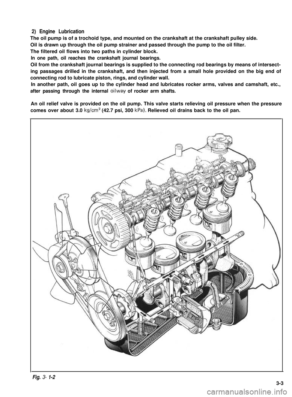
2) Engine Lubrication
The oil pump is of a trochoid type, and mounted on the crankshaft at the crankshaft pulley side.
Oil is drawn up through the oil pump strainer and passed through the pump to the oil filter.
The filtered oil flows into two paths in cylinder block.
In one path, oil reaches the crankshaft journal bearings.
Oil from the crankshaft journal bearings is supplied to the connecting rod bearings by means of intersect-
ing passages drilled in the crankshaft, and then injected from a small hole provided on the big end of
connecting rod to lubricate piston, rings, and cylinder wall.
In another path, oil goes up to the cylinder head and lubricates rocker arms, valves and camshaft, etc.,
after passing through the internal oilway of rocker arm shafts.
An oil relief valve is provided on the oil pump. This valve starts relieving oil pressure when the pressure
comes over about 3.0 kg/cm2 (42.7 psi, 300 kPa). Relieved oil drains back to the oil pan.
Fig. 3- 1-2
3-3