SUZUKI GRAND VITARA 1987 Service Manual PDF
Manufacturer: SUZUKI, Model Year: 1987, Model line: GRAND VITARA, Model: SUZUKI GRAND VITARA 1987Pages: 962, PDF Size: 27.87 MB
Page 61 of 962
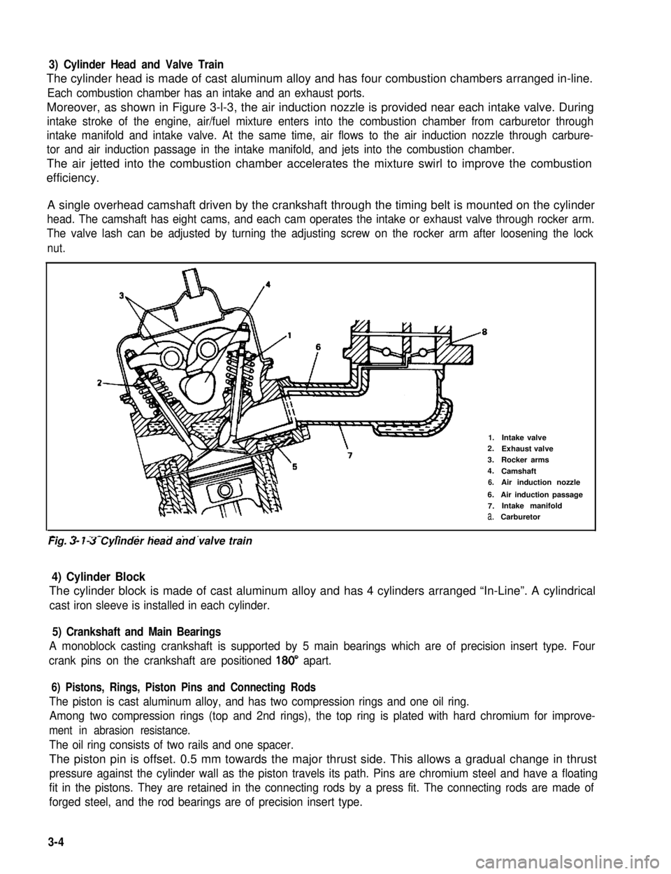
3) Cylinder Head and Valve Train
The cylinder head is made of cast aluminum alloy and has four combustion chambers arranged in-line.
Each combustion chamber has an intake and an exhaust ports.
Moreover, as shown in Figure 3-l-3, the air induction nozzle is provided near each intake valve. During
intake stroke of the engine, air/fuel mixture enters into the combustion chamber from carburetor through
intake manifold and intake valve. At the same time, air flows to the air induction nozzle through carbure-
tor and air induction passage in the intake manifold, and jets into the combustion chamber.
The air jetted into the combustion chamber accelerates the mixture swirl to improve the combustion
efficiency.
A single overhead camshaft driven by the crankshaft through the timing belt is mounted on the cylinder
head. The camshaft has eight cams, and each cam operates the intake or exhaust valve through rocker arm.
The valve lash can be adjusted by turning the adjusting screw on the rocker arm after loosening the lock
nut.
2-
1.Intake valve2.Exhaust valve
3.Rocker arms
4.Camshaft
6.Air induction nozzle
6.Air induction passage
7.Intake manifold
a.Carburetor
-. - _- - ._ . . . . .Fig. 3- 7-3 Cylinder head and valve train
4) Cylinder Block
The cylinder block is made of cast aluminum alloy and has 4 cylinders arranged “In-Line”. A cylindrical
cast iron sleeve is installed in each cylinder.
5) Crankshaft and Main Bearings
A monoblock casting crankshaft is supported by 5 main bearings which are of precision insert type. Four
crank pins on the crankshaft are positioned 180” apart.
6) Pistons, Rings, Piston Pins and Connecting Rods
The piston is cast aluminum alloy, and has two compression rings and one oil ring.
Among two compression rings (top and 2nd rings), the top ring is plated with hard chromium for improve-
ment in abrasion resistance.
The oil ring consists of two rails and one spacer.
The piston pin is offset. 0.5 mm towards the major thrust side. This allows a gradual change in thrust
pressure against the cylinder wall as the piston travels its path. Pins are chromium steel and have a floating
fit in the pistons. They are retained in the connecting rods by a press fit. The connecting rods are made of
forged steel, and the rod bearings are of precision insert type.
3-4
Page 62 of 962
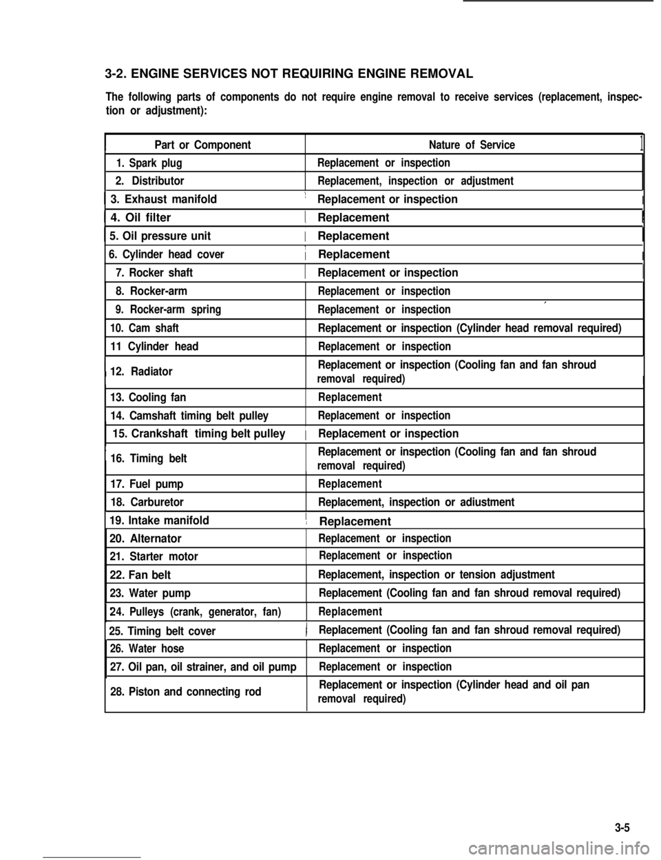
3-2. ENGINE SERVICES NOT REQUIRING ENGINE REMOVAL
The following parts of components do not require engine removal to receive services (replacement, inspec-
tion or adjustment):
Part or ComponentNature of Service1
1. Spark plug
2. Distributor
Replacement or inspection
Replacement, inspection or adjustment
1 3. Exhaust manifold1 Replacement or inspectionI
I 4. Oil filter1 ReplacementI
1 5. Oil pressure unit( Replacement
6. Cylinder head cover1 ReplacementI
I7. Rocker shaft1 Replacement or inspectionI
8. Rocker-arm
9. Rocker-arm spring
Replacement or inspection
Replacement or inspectionI
10. Cam shaft
11 Cylinder head
I12. Radiator
Replacement or inspection (Cylinder head removal required)
Replacement or inspection
Replacement or inspection (Cooling fan and fan shroud
removal required)I
13. Cooling fan
14. Camshaft timing belt pulley
Replacement
Replacement or inspection
I
15. Crankshaft timing belt pulley
16. Timing beltReplacement or inspection (Cooling fan and fan shroud
1 Replacement or inspection
removal required)
17. Fuel pump
18. Carburetor
Replacement
Replacement, inspection or adiustment
19. Intake manifold1 ReplacementI
20. Alternator
21. Starter motor
Replacement or inspection
22. Fan belt
23. Water pump
Replacement, inspection or tension adjustment
Replacement (Cooling fan and fan shroud removal required)
24.Pulleys (crank, generator, fan)Replacement
25. Timing belt cover)Replacement (Cooling fan and fan shroud removal required)
26. Water hose
27. Oil pan, oil strainer, and oil pump
Replacement or inspection
Replacement or inspection
28. Piston and connecting rodReplacement or inspection (Cylinder head and oil pan
removal required)
Replacement or inspection
3-5
Page 63 of 962
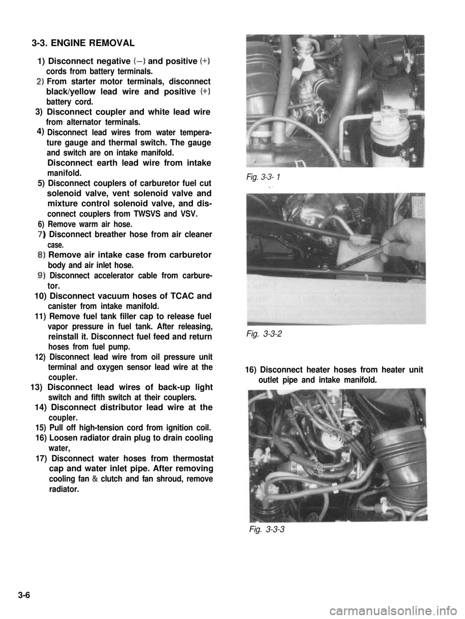
3-3. ENGINE REMOVAL
1) Disconnect negative (-) and positive (+)
cords from battery terminals.
‘)From starter motor terminals, disconnect
black/yellow lead wire and positive (+)
battery cord.
Disconnect coupler and white lead wire
from alternator terminals.
Disconnect lead wires from water tempera-
ture gauge and thermal switch. The gauge
and switch are on intake manifold.
Disconnect earth lead wire from intake
manifold.
5) Disconnect couplers of carburetor fuel cut
solenoid valve, vent solenoid valve and
mixture control solenoid valve, and dis-
connect couplers from TWSVS and VSV.
6) Remove warm air hose.
) Disconnect breather hose from air cleaner
case.
,) Remove air intake case from carburetor
body and air inlet hose.
1) Disconnect accelerator cable from carbure-
tor.
10) Disconnect vacuum hoses of TCAC and
canister from intake manifold.
11) Remove fuel tank filler cap to release fuel
vapor pressure in fuel tank. After releasing,
reinstall it. Disconnect fuel feed and return
hoses from fuel pump.
12) Disconnect lead wire from oil pressure unit
terminal and oxygen sensor lead wire at the
coupler.
13) Disconnect lead wires of back-up light
switch and fifth switch at their couplers.
14) Disconnect distributor lead wire at the
coupler.
15) Pull off high-tension cord from ignition coil.
16) Loosen radiator drain plug to drain cooling
water,
17) Disconnect water hoses from thermostat
cap and water inlet pipe. After removing
cooling fan & clutch and fan shroud, remove
radiator.
Fig. 3-3- 1
Fig. 3-3-2
16) Disconnect heater hoses from heater unit
outlet pipe and intake manifold.
Fig. 3-3-3
3)
4)
3-6
Page 64 of 962
19) Disconnect brake booster vacuum hose from
pipe.
20) Disconnect coupler of lead wire (black) from distributor gear case.
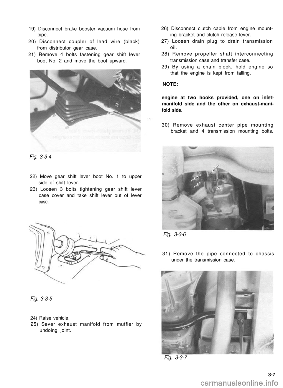
21) Remove 4 bolts fastening gear shift lever boot No. 2 and move the boot upward.Fig. 3-3-4
22) Move gear shift lever boot No. 1 to upperside of shift lever.
23) Loosen 3 bolts tightening gear shift lever case cover and take shift lever out of lever
case.
26) Disconnect clutch cable from engine mount- ing bracket and clutch release lever.
27) Loosen drain plug to drain transmission oil.
28) Remove propeller shaft interconnecting transmission case and transfer case.
29) By using a chain block, hold engine so that the engine is kept from falling.
NOTE:
engine at two hooks provided, one on
inlet-
manifold side and the other on exhaust-mani-
fold side.
30) Remove exhaust center pipe mounting bracket and 4 transmission mounting bolts.
Fig. 3-3-6
31) Remove the pipe connected to chassis
under the transmission case.
Fig. 3-3-5
24) Raise vehicle.25) Sever exhaust manifold from muffler by undoing joint.
Fig. 3-3-7
3-7
Page 65 of 962
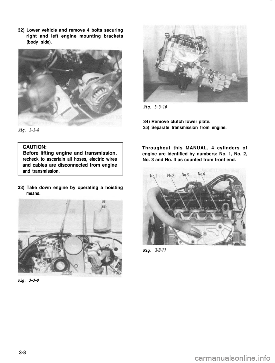
32) Lower vehicle and remove 4 bolts securing
right and left engine mounting brackets(body side).
Fig. 3-3-10
Fig. 3-3-8
CAUTION:Before lifting engine and transmission,
recheck to ascertain all hoses, electric wires
and cables are disconnected from engine
and transmission.
34) Remove clutch lower plate.
35) Separate transmission from engine.
Throughout this MANUAL, 4 cylinders ofengine are identified by numbers: No. 1, No. 2, No. 3 and No. 4 as counted from front end.
33) Take down engine by operating a hoisting
means.
Fig. 3-3-11
Fig. 3-3-9
3-8
Page 66 of 962
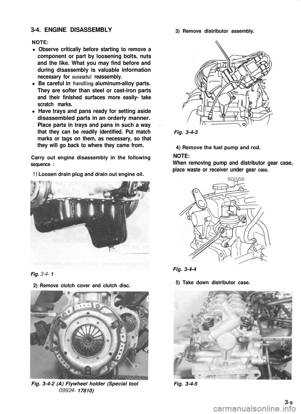
3-4. ENGINE DISASSEMBLY
NOTE:
3) Remove distributor assembly.
l Observe critically before starting to remove a
component or part by loosening bolts, nuts
and the like. What you may find before and
during disassembly is valuable information
necessary for sucessful reassembly.
l Be careful in .handling aluminum-alloy parts.
They are softer than steel or cast-iron parts
and their finished surfaces more easily- take
scratch marks.
l Have trays and pans ready for setting aside
disassembled parts in an orderly manner.
Place parts in trays and pans in such a way_.
that they can be readily identified. Put matchFig. 3-4-3
marks or tags on them, as necessary, so that
they will go back to where they came from.
4) Remove the fuel pump and rod.
Carry out engine disassembly in the following
NOTE:
sequence :When removing pump and distributor gear case,
1) Loosen drain plug and drain out engine oil.place waste or receiver under gear casa.
Fig. 3-4-4Fig. 3-4- 1
2) Remove clutch cover and clutch disc. 5) Take down distributor case.
Fig. 3-4-2 (A) Flywheel holder (Special tool09924-
17810) Fig. 3-4-5
Page 67 of 962
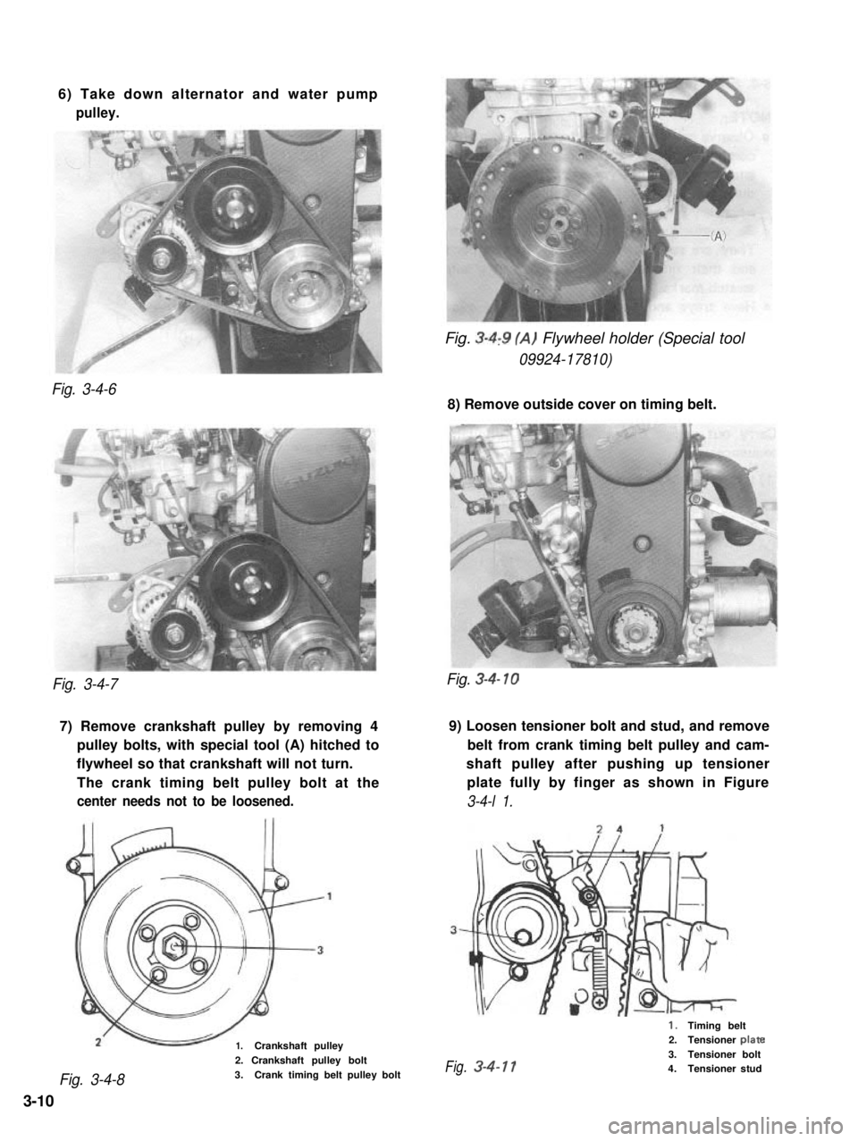
6) Take down alternator and water pump
pulley.
Fig. 3-4,9 (A) Flywheel holder (Special tool
09924-17810)
Fig. 3-4-6
8) Remove outside cover on timing belt.
Fig. 3-4-7
7) Remove crankshaft pulley by removing 49) Loosen tensioner bolt and stud, and remove
pulley bolts, with special tool (A) hitched tobelt from crank timing belt pulley and cam-
flywheel so that crankshaft will not turn.shaft pulley after pushing up tensioner
The crank timing belt pulley bolt at theplate fully by finger as shown in Figure
center needs not to be loosened.3-4-l 1.
1.Crankshaft pulley
Fig. 3-4-8
2. Crankshaft pulley bolt
3.Crank timing belt pulley bolt
Fig. 3-4- 10
1.Timing belt2.Tensioner plate
3.Tensioner boltFig.3-4-114.Tensioner stud
3-10
Page 68 of 962
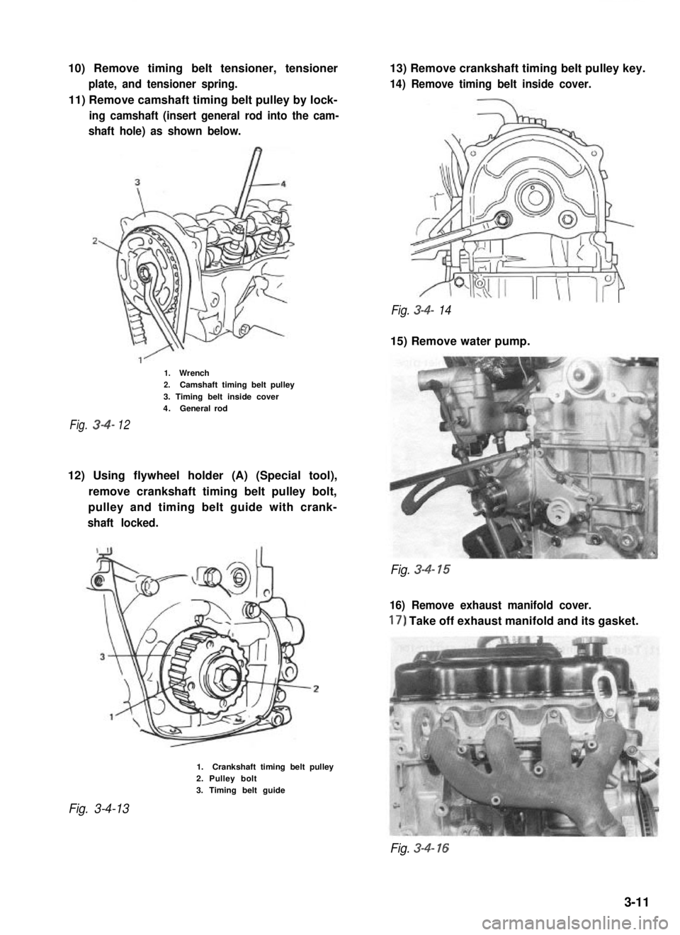
10) Remove timing belt tensioner, tensioner
plate, and tensioner spring.
11) Remove camshaft timing belt pulley by lock-
ing camshaft (insert general rod into the cam-
shaft hole) as shown below.
13) Remove crankshaft timing belt pulley key.
14) Remove timing belt inside cover.
Fig. 3-4- 14
15) Remove water pump.
1.Wrench2.Camshaft timing belt pulley
3. Timing belt inside cover4.Generalrod
Fig.3412
12) Using flywheel holder (A) (Special tool),
remove crankshaft timing belt pulley bolt,
pulley and timing belt guide with crank-
shaft locked.
Fig. 3-4- 15
16) Remove exhaust manifold cover.
17) Take off exhaust manifold and its gasket.
Fig. 3-4-13
1.Crankshaft timing belt pulley2. Pulley bolt3. Timing belt guide
Fig. 3-4- 16
3-11
Page 69 of 962
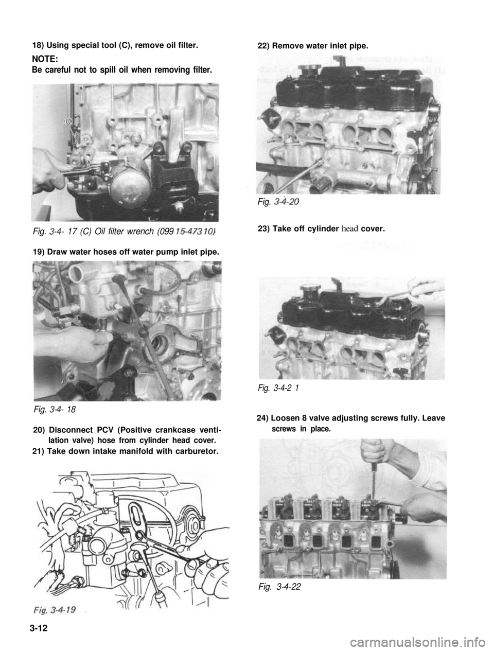
18) Using special tool (C), remove oil filter.
NOTE:
Be careful not to spill oil when removing filter.
22) Remove water inlet pipe.
Fig. 3-4- 17 (C) Oil filter wrench (099 15-473 10)
19) Draw water hoses off water pump inlet pipe.
Fig. 3-4-2 1
Fig. 3-4- 18
20) Disconnect PCV (Positive crankcase venti-
lation valve) hose from cylinder head cover.
21) Take down intake manifold with carburetor.
Fig. 3-4120
23) Take off cylinder head cover.
24) Loosen 8 valve adjusting screws fully. Leave
screws in place.
Fig. 3-4-22
3-12
Page 70 of 962
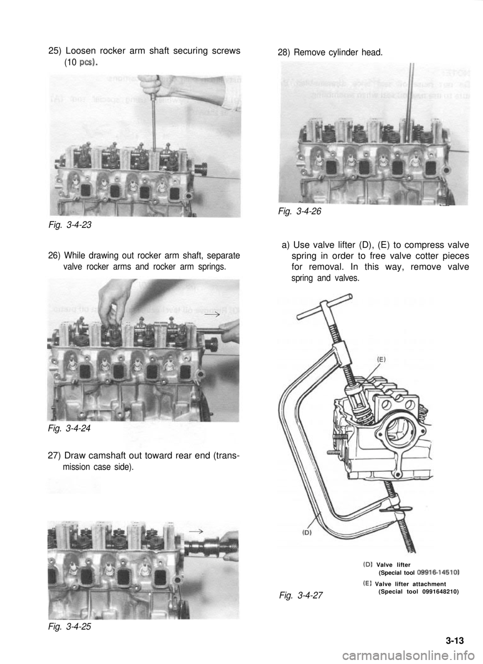
25) Loosen rocker arm shaft securing screws
(10 PCS).
Fig. 3-4-23
26) While drawing out rocker arm shaft, separate
valve rocker arms and rocker arm springs.
Fig. 3-4-24
27) Draw camshaft out toward rear end (trans-
mission case side).
28) Remove cylinder head.
____Fig. 3-4-26
a) Use valve lifter (D), (E) to compress valve
spring in order to free valve cotter pieces
for removal. In this way, remove valve
spring and valves.
(D) Valve lifter(Special tool 09916-14510)
(El Valve lifter attachment
Fig. 3-4-27(Special tool 0991648210)
Fig. 3-4-25
3-13