SUZUKI GRAND VITARA 1987 Service Manual Online
Manufacturer: SUZUKI, Model Year: 1987, Model line: GRAND VITARA, Model: SUZUKI GRAND VITARA 1987Pages: 962, PDF Size: 27.87 MB
Page 81 of 962
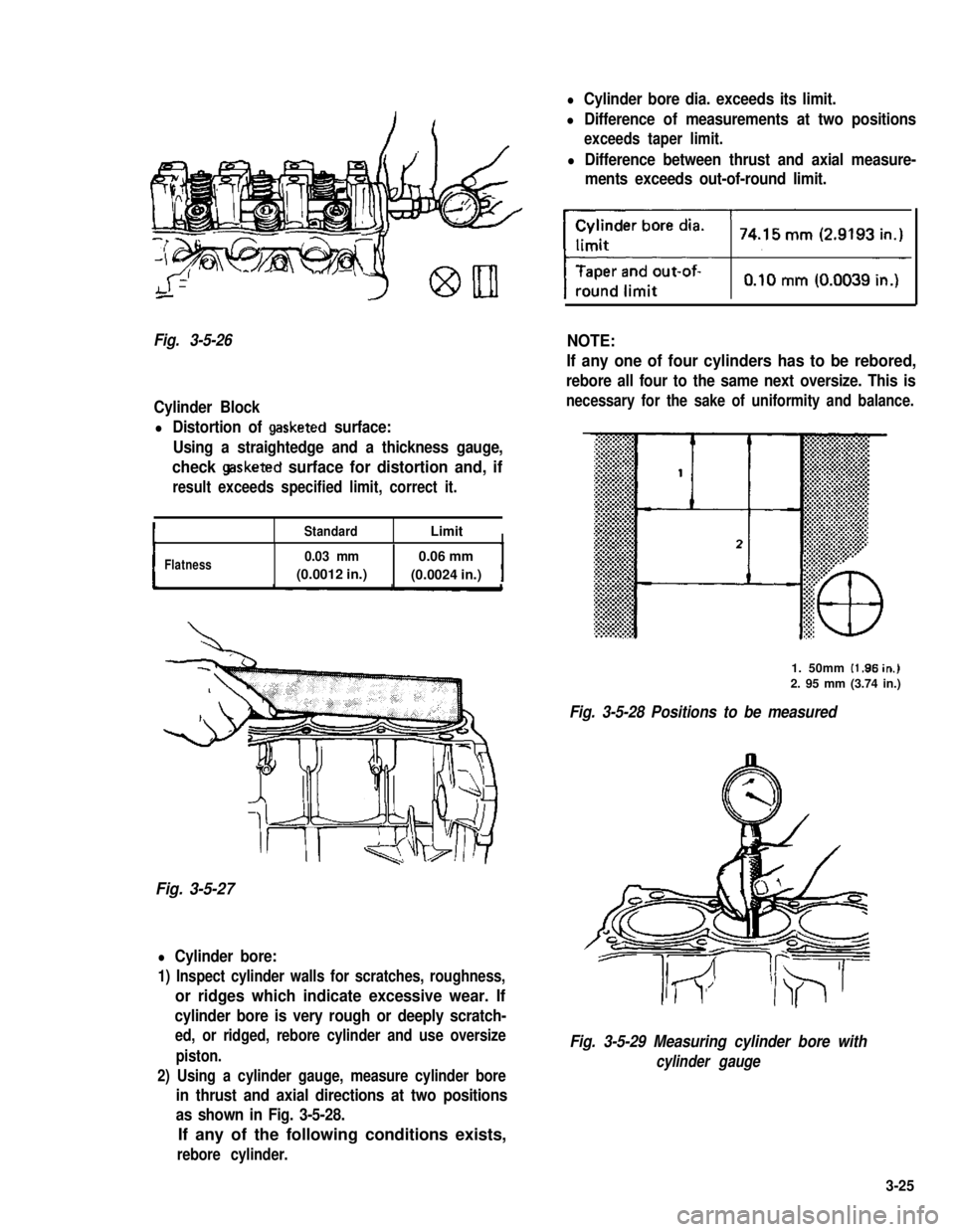
Fig. 3-5-26
Cylinder Block
l Distortion of gasketed surface:
Using a straightedge and a thickness gauge,
check gasketed surface for distortion and, if
result exceeds specified limit, correct it.
StandardLimitI
IFlatness0.03 mm0.06 mm
(0.0012 in.)(0.0024 in.)I
Fig. 3-5-27
l Cylinder bore:
1) Inspect cylinder walls for scratches, roughness,
or ridges which indicate excessive wear. If
cylinder bore is very rough or deeply scratch-
ed, or ridged, rebore cylinder and use oversize
piston.
2) Using a cylinder gauge, measure cylinder bore
in thrust and axial directions at two positions
as shown in Fig. 3-5-28.
If any of the following conditions exists,
rebore cylinder.
l Cylinder bore dia. exceeds its limit.
l Difference of measurements at two positions
exceeds taper limit.
l Difference between thrust and axial measure-
ments exceeds out-of-round limit.
NOTE:
If any one of four cylinders has to be rebored,
rebore all four to the same next oversize. This is
necessary for the sake of uniformity and balance.
1. 50mm (1.96in.j
2. 95 mm (3.74 in.)
Fig. 3-5-28 Positions to be measured
Fig. 3-5-29 Measuring cylinder bore with
cylinder gauge
3-25
Page 82 of 962
l Honing or reboring cylinders:
1) When any cylinder needs reboring, all other
cylinders must also be rebored at same time.
2) Select oversized piston according to amount
of cylinder wear.
ISizeIPiston diameter
O/S0.2574.220 74.230-mm
(2.9220 - 2.9224in.)
74.470 74.480-o/s0.50mm
(2.9318 - 2.9322in.)
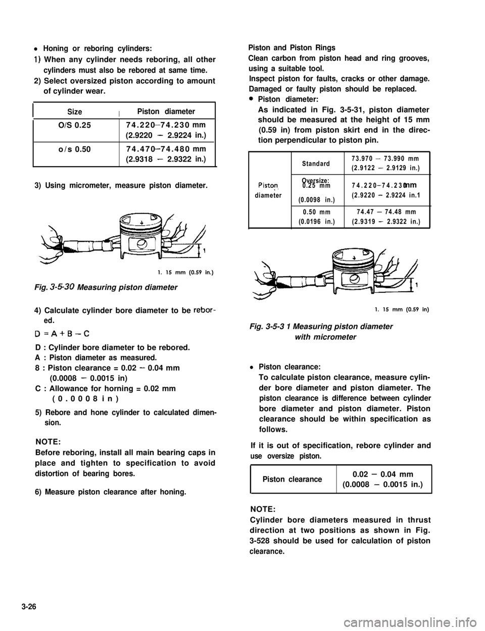
3) Using micrometer, measure piston diameter.
1. 15 mm (0.59 in.)
Fig. 3-5-30 Measuring piston diameter
4) Calculate cylinder bore diameter to be rebor-
ed.
D=A+B-C
D : Cylinder bore diameter to be rebored.
A : Piston diameter as measured.
8 : Piston clearance = 0.02 - 0.04 mm
(0.0008 - 0.0015 in)
C : Allowance for horning = 0.02 mm
(0.0008 in)
5) Rebore and hone cylinder to calculated dimen-
sion.
NOTE:
Before reboring, install all main bearing caps in
place and tighten to specification to avoid
distortion of bearing bores.
6) Measure piston clearance after honing.
Piston and Piston Rings
Clean carbon from piston head and ring grooves,
using a suitable tool.
Inspect piston for faults, cracks or other damage.
Damaged or faulty piston should be replaced.
0Piston diameter:
As indicated in Fig. 3-5-31, piston diameter
should be measured at the height of 15 mm
(0.59 in) from piston skirt end in the direc-
tion perpendicular to piston pin.
Standard73.970 - 73.990 mm
(2.9122 - 2.9129 in.)
Piston
diameter
Oversize:0.25 mm
(0.0098 in.)
0.50 mm
(0.0196 in.)
74.220 74.230- mm
(2.9220 - 2.9224 in.1
74.47 - 74.48 mm
(2.9319 - 2.9322 in.)
1. 15 mm (0.59 in)
Fig. 3-5-3 1 Measuring piston diameter
with micrometer
l Piston clearance:
To calculate piston clearance, measure cylin-
der bore diameter and piston diameter. The
piston clearance is difference between cylinder
bore diameter and piston diameter. Piston
clearance should be within specification as
follows.
If it is out of specification, rebore cylinder and
use oversize piston.
Piston clearance0.02 - 0.04 mm
(0.0008 - 0.0015 in.)
NOTE:
Cylinder bore diameters measured in thrust
direction at two positions as shown in Fig.
3-528 should be used for calculation of piston
clearance.
3-26
Page 83 of 962
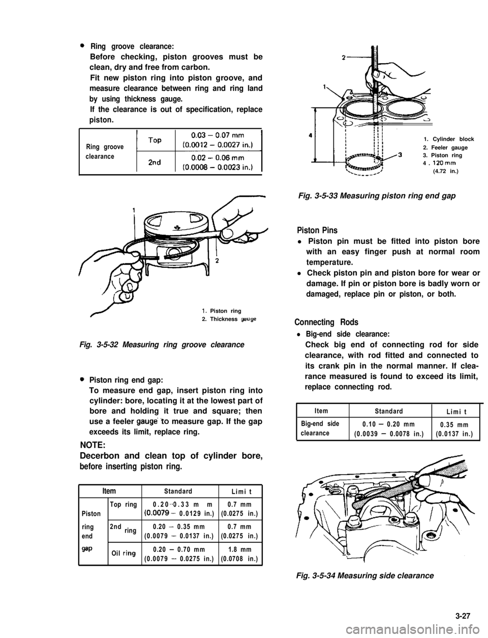
0Ring groove clearance:
Before checking, piston grooves must be
clean, dry and free from carbon.
Fit new piston ring into piston groove, and
measure clearance between ring and ring land
by using thickness gauge.
If the clearance is out of specification, replace
piston.
Ring groove
clearanceti1
1. Piston ring
2. Thickness geuge
Fig. 3-5-32 Measuring ring groove clearance
0Piston ring end gap:
To measure end gap, insert piston ring into
cylinder: bore, locating it at the lowest part of
bore and holding it true and square; then
use a feeler gauge’to measure gap. If the gap
exceeds its limit, replace ring.
NOTE:
Decerbon and clean top of cylinder bore,
before inserting piston ring.
ItemStandardLimit
Top ring0.20 0.33 mm-0.7 mm
Piston(0.0079 - 0.0129in.)(0.0275 in.)
ring2ndring0.20 - 0.35 mm0.7 mm
end(0.0079 - 0.0137 in.)(0.0275 in.)
QaPOil riilg0.20 - 0.70 mm1.8 mm
(0.0079 - 0.0275 in.)(0.0708 in.)
1. Cylinder block
2. Feeler gauge3. Piston ring4. 12Omm(4.72 in.)
Fig. 3-5-33 Measuring piston ring end gap
Piston Pins
l Piston pin must be fitted into piston bore
with an easy finger push at normal room
temperature.
l Check piston pin and piston bore for wear or
damage. If pin or piston bore is badly worn or
damaged, replace pin or piston, or both.
Connecting Rods
l Big-end side clearance:
Check big end of connecting rod for side
clearance, with rod fitted and connected to
its crank pin in the normal manner. If clea-
rance measured is found to exceed its limit,
replace connecting rod.
Item
Big-end side
clearance
StandardLimit
0.10 - 0.20 mm0.35 mm
(0.0039 - 0.0078 in.)(0.0137 in.)
Fig. 3-5-34 Measuring side clearance
3-27
Page 84 of 962
l Connecting rod alignment:
Mount connecting rod on aligner to check
it for bow and twist and, if either limit is
exceeded, replace it.
Limit on bow0.05 mm (0.0020 in.)
ILimit on twist) 0.10 mm (0.0039 in.) 1
Crank Pin and Connecting Rod Bearings
l Inspect crank pin for uneven wear or damage.
Measure crank pin for out-of-round or taper
with a micrometer. If crank pin is damaged,
or out-of-round or taper is out of limit,
replace crankshaft or regrind crank pin to
undersize and use undersize bearing.
I
Connecting
rod bearing sizeCrank pin diameterI
IStandard41.982 - 42.000 mm
(1.6529 - 1.6535 in.)I
0.25 mm (0.0098 in.)41.732 - 41.750 mm
undersize(1.6430 - 1.6437 in.)
Out-of-round and
taper limit0.01 mm (0.0004 in.)
l Rod bearing:
Inspect bearing shells for signs of fusion,
pitting, burn or flaking and observe contact
pattern. Bearing shells found in defective
condition must be replaced.
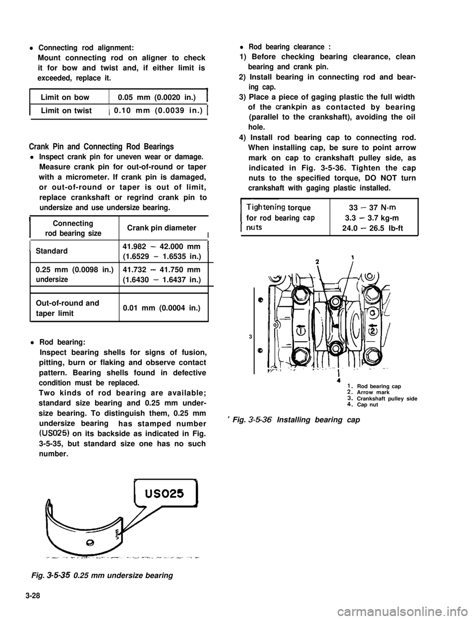
Two kinds of rod bearing are available;
standard size bearing and 0.25 mm under-
size bearing. To distinguish them, 0.25 mm
undersize bearinghas stamped number
(USO25) on its backside as indicated in Fig.
3-5-35, but standard size one has no such
number.
l Rod bearing clearance :
1) Before checking bearing clearance, clean
bearing and crank pin.
2) Install bearing in connecting rod and bear-
ing cap.
3) Place a piece of gaging plastic the full width
of the crankpin as contacted by bearing
(parallel to the crankshaft), avoiding the oil
hole.
4) Install rod bearing cap to connecting rod.
When installing cap, be sure to point arrow
mark on cap to crankshaft pulley side, as
indicated in Fig. 3-5-36. Tighten the cap
nuts to the specified torque, DO NOT turn
crankshaft with gaging plastic installed.
torque33-37 N-m
forrodbearingcap3.3-3.7 kg-m
24.0-26.5 lb-ft
e
3
0
.
’ Fig. 3-5-36 Installing bearing cap
Rod bearing capArrow markCrankshaft pulley sideCap nut
Fig. 3-5-35 0.25 mm undersize bearing
3-28
Page 85 of 962
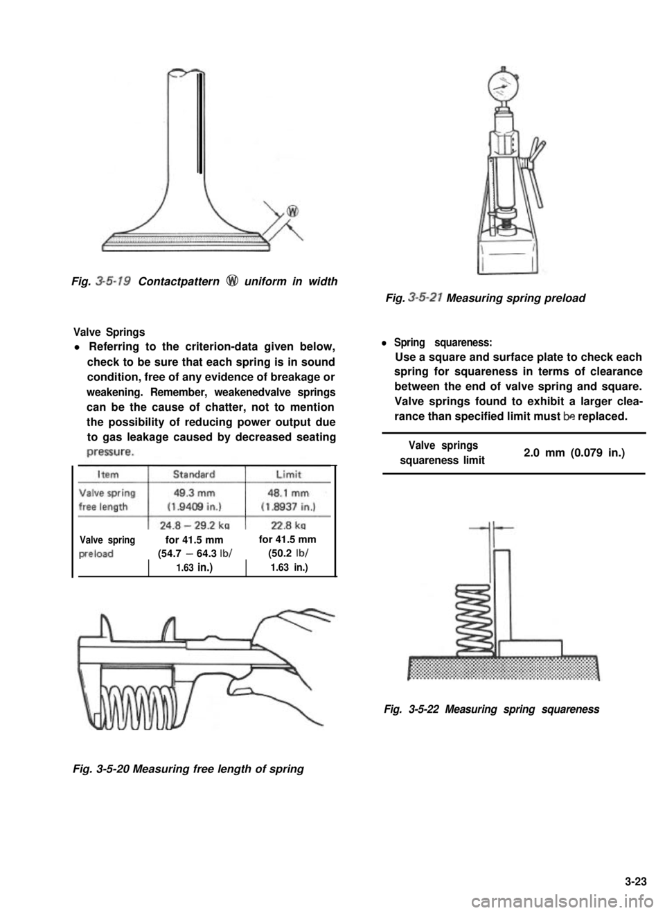
Fig. 3-5-19 Contactpattern @ uniform in width
Valve Springs
l Referring to the criterion-data given below,
check to be sure that each spring is in sound
condition, free of any evidence of breakage or
weakening. Remember, weakenedvalve springs
can be the cause of chatter, not to mention
the possibility of reducing power output due
to gas leakage caused by decreased seating
Valve springfor 41.5 mmfor 41.5 mm
preload(54.7 - 64.3 lb/(50.2 lb/
1.63 in.)1.63 in.)
Fig. 3-5-21 Measuring spring preload
l Spring squareness:
Use a square and surface plate to check each
spring for squareness in terms of clearance
between the end of valve spring and square.
Valve springs found to exhibit a larger clea-
rance than specified limit must be replaced.
Valve springs
squareness limit2.0 mm (0.079 in.)
Fig. 3-5-22 Measuring spring squareness
Fig. 3-5-20 Measuring free length of spring
3-23
Page 86 of 962

c5) Remove cap and using scale on gaging bIastic
envelope, measure gaging plastic width at
the widest point.
If the clearance exceeds its limit, use a new
standard size bearing and remeasure clea-
rance.
1. Gaging plastic2. Scale
Fig. 3-5-37 Measuring rod bearing clearance
6) If clearance can not be brought to within
limit even by using a new standard size bear-
ing, regrind crankpin to the undersizeand use
0.25 mm undersize bearing.
Crankshaft
l Crankshaft runout:
Using a dial gauge, measure runout at center
journal. Rotate crankshaft slowly. If runout
exceeds limit, replace crankshaft.
Limit on runout0.06 mm (0.0023 in.)
l Crankshaft thrust play :
Measure this play with crankshaft set in
cylinder block in the normal manner, that is,
with thrust bearing fitted and journal bearing
caps installed. Tighten bearing cap bolts to
specified torque.
Use a dial gauge to read displacement in axial
(thrust) direction of crankshaft.
If the limit is exceeded, replace thrust bearing
with new standard one or oversize one to
obtain standard thrust play.
ItemStandardLimit
Crankshaft0.11 - 0.31 mm0.38 mm
thrust play(0.0044 - 0.0122 in.)(0.0149 in.)
-.Thickness of
crankshaft
thrust bearing
1, Thrust bearing
Fig. 3-5-39 Thrust bearings
Fig. 3-5-38 Measuring runou t
3-29
Page 87 of 962

Crankshaft Main (Journal) Bearings
General informations:
l Service main bearings are available in standard-
size and 0.25 mm (0.0098 in) undersize, and
each of them has 5 kinds of bearings differ-
ing in tolerance.
l The upper half of bearing has oil groove as
indicated in Fig. 3~5-42. Install this half with
oil groove to cylinder block.
Fig. 3-5-40 Measuring thrust play of crankshaft
l Out-of-round and taper (uneven wear):
An unevenly worn crankshaft journal shows
up as a difference in diameter at a cross
section or along its length (or both). This
difference, if any, is to be determined from
micrometer readings.
If any of journals is badly damaged or if the
amount of uneven wear in the sense explained
above exceeds its limit, regrind or replace the
crankshaft.
I
Limit on out-of-round
and taper0.01 mm (0.0004 in.)
Fig. 3-5-4 1 Checking uneven wear
1. Cylinder block2. Upper half of bearing
3. Oil groove
Fig. 3-5-42 Upper half of bearing installation
l On each main bearing cap, arrow mark and
number are embossed as indicated in Fig.
3-5-43.
When installing each bearing cap to cylinder
block, point arrow mark toward crankshaft
pulley side and install each cap from crank-
shaft pulley side to flywheel side in ascending
order of numbers @,a, 0, @ and 0. Tigh-
ten cap bolts to specified torque.
3
2. Flywheel side
Fig. 3-5-43 Bearing caps ins talla tion
3-30
Page 88 of 962
inspect:
Check bearings for pitting, scratches, wear or
damage. If any malcondition is found, replace
both upper and lower halves. Never replace one
half without replacing the other half.
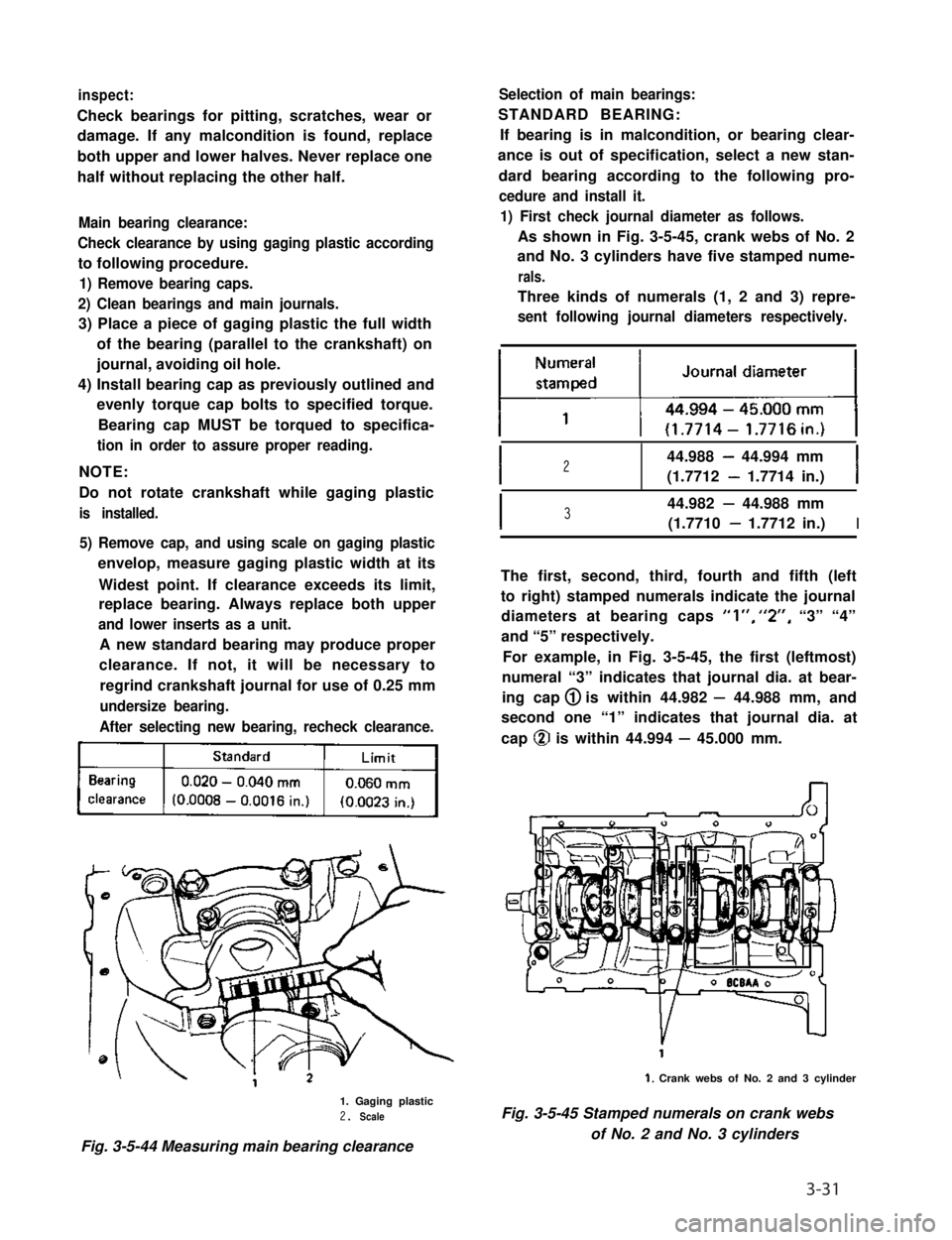
Main bearing clearance:
Check clearance by using gaging plastic according
to following procedure.
1) Remove bearing caps.
2) Clean bearings and main journals.
3) Place a piece of gaging plastic the full width
of the bearing (parallel to the crankshaft) on
journal, avoiding oil hole.
4) Install bearing cap as previously outlined and
evenly torque cap bolts to specified torque.
Bearing cap MUST be torqued to specifica-
tion in order to assure proper reading.
NOTE:
Do not rotate crankshaft while gaging plastic
is installed.
5) Remove cap, and using scale on gaging plastic
envelop, measure gaging plastic width at its
Widest point. If clearance exceeds its limit,
replace bearing. Always replace both upper
and lower inserts as a unit.
A new standard bearing may produce proper
clearance. If not, it will be necessary to
regrind crankshaft journal for use of 0.25 mm
undersize bearing.
After selecting new bearing, recheck clearance.
kj
1. Gaging plastic2. Scale
Fig. 3-5-44 Measuring main bearing clearance
Selection of main bearings:
STANDARD BEARING:
If bearing is in malcondition, or bearing clear-
ance is out of specification, select a new stan-
dard bearing according to the following pro-
cedure and install it.
1) First check journal diameter as follows.
As shown in Fig. 3-5-45, crank webs of No. 2
and No. 3 cylinders have five stamped nume-
rals.
Three kinds of numerals (1, 2 and 3) repre-
sent following journal diameters respectively.
I244.988 - 44.994 mm
(1.7712 - 1.7714 in.)I
I344.982 - 44.988 mm
(1.7710 - 1.7712 in.)I
The first, second, third, fourth and fifth (left
to right) stamped numerals indicate the journal
diameters at bearing caps “l”, “2”, “3” “4”
and “5” respectively.
For example, in Fig. 3-5-45, the first (leftmost)
numeral “3” indicates that journal dia. at bear-
ing cap 1 is within 44.982 - 44.988 mm, and
second one “1” indicates that journal dia. at
cap @ is within 44.994 - 45.000 mm.
1. Crank webs of No. 2 and 3 cylinder
Fig. 3-5-45 Stamped numerals on crank webs
of No. 2 and No. 3 cylinders
3-31
Page 89 of 962
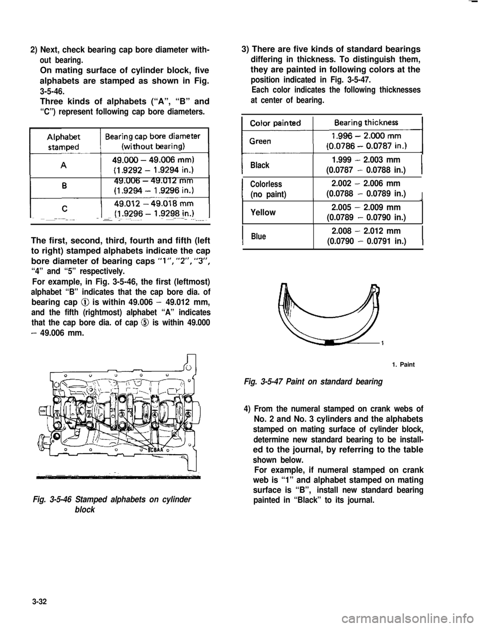
2) Next, check bearing cap bore diameter with-
out bearing.
On mating surface of cylinder block, five
alphabets are stamped as shown in Fig.
3-5-46.
Three kinds of alphabets (“A”, “B” and
“C”) represent following cap bore diameters.
The first, second, third, fourth and fifth (left
to right) stamped alphabets indicate the cap
bore diameter of bearing caps “l”, “2”, “3”,
“4” and “5” respectively.
For example, in Fig. 3-5-46, the first (leftmost)
alphabet “B” indicates that the cap bore dia. of
bearing cap @ is within 49.006 - 49.012 mm,
and the fifth (rightmost) alphabet “A” indicates
that the cap bore dia. of cap @ is within 49.000
- 49.006 mm.
Fig. 3-5-46 Stamped alphabets on cylinder
block
3) There are five kinds of standard bearings
differing in thickness. To distinguish them,
they are painted in following colors at the
position indicated in Fig. 3-5-47.
Each color indicates the following thicknesses
at center of bearing.
IBlack1.999 - 2.003 mm
(0.0787 - 0.0788 in.)I
I
Colorless2.002 - 2.006 mm
(no paint)(0.0788 - 0.0789 in.)I9
Yellow2.005 - 2.009 mm
(0.0789 - 0.0790 in.)
IBlue2.008 - 2.012 mm
(0.0790 - 0.0791 in.)I
1. Paint
Fig. 3-5-47 Paint on standard bearing
4) From the numeral stamped on crank webs of
No. 2 and No. 3 cylinders and the alphabets
stamped on mating surface of cylinder block,
determine new standard bearing to be install-
ed to the journal, by referring to the table
shown below.
For example, if numeral stamped on crank
web is “1” and alphabet stamped on mating
surface is “B”,install new standard bearing
painted in “Black” to its journal.
3-32
Page 90 of 962
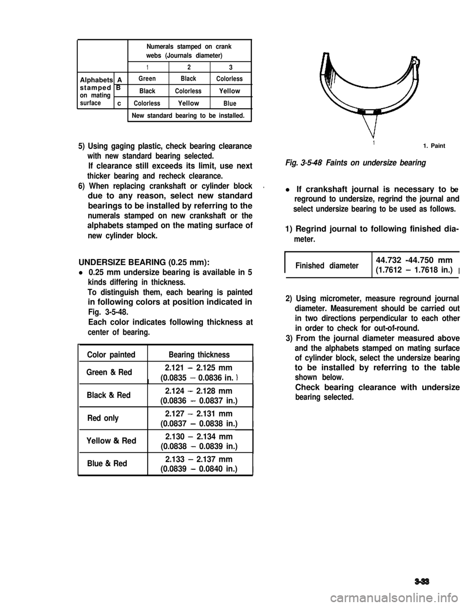
Numerals stamped on crank
webs (Journals diameter)
123
Alphabets AGreenBlackColorless
stamped Bon matingBlackColorlessYellow
surfacecColorlessYellowBlue
New standard bearing to be installed.
5) Using gaging plastic, check bearing clearance
with new standard bearing selected.
If clearance still exceeds its limit, use next
thicker bearing and recheck clearance.
6) When replacing crankshaft or cylinder block.
due to any reason, select new standard
bearings to be installed by referring to the
numerals stamped on new crankshaft or the
alphabets stamped on the mating surface of
new cylinder block.
UNDERSIZE BEARING (0.25 mm):
l 0.25 mm undersize bearing is available in 5
kinds differing in thickness.
To distinguish them, each bearing is painted
in following colors at position indicated in
Fig. 3-5-48.
Each color indicates following thickness at
center of bearing.
Color paintedBearing thicknessI
Green & Red2.121 - 2.125 mm
(0.0835 - 0.0836 in. )III
Black & Red2.124 - 2.128 mm
(0.0836 - 0.0837 in.)
Red only2.127 - 2.131 mm
(0.0837 - 0.0838 in.)I
Yellow & Red2.130 - 2.134 mm
(0.0838 - 0.0839 in.)
Blue & Red2.133 - 2.137 mm
(0.0839 - 0.0840 in.)I
11. Paint
Fig. 3-5-48 Faints on undersize bearing
l If crankshaft journal is necessary to be
reground to undersize, regrind the journal and
select undersize bearing to be used as follows.
1) Regrind journal to following finished dia-
meter.
IFinished diameter44.732 -44.750 mm
(1.7612 - 1.7618 in.)I
2) Using micrometer, measure reground journal
diameter. Measurement should be carried out
in two directions perpendicular to each other
in order to check for out-of-round.
3) From the journal diameter measured above
and the alphabets stamped on mating surface
of cylinder block, select the undersize bearing
to be installed by referring to the table
shown below.
Check bearing clearance with undersize
bearing selected.
3-33